
SH 80 S - Boiler STIEBEL ELTRON - Free user manual and instructions
Find the device manual for free SH 80 S STIEBEL ELTRON in PDF.
| Brand | Stiebel Eltron |
| Model | SH 80 S |
| Product type | Electric boiler (water heater) |
| Nominal capacity | 80 liters |
| Dimensions (H x W x D) | 1050 x 510 x 510 mm |
| Weight empty | 38 kg |
| Weight loaded | 118 kg |
| Electrical supply | 230/400 V, 50 Hz, single-phase or three-phase |
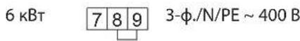
| Connection power | 1-4 kW (230 V) / 3-6 kW (400 V) |
| Temperature range | 35-82 °C |
| Maximum permissible pressure | 0.6 MPa |
| Maximum flow rate | 18 l/min |
| Frost protection | Yes, via minimum setting and electrical supply |
| Heat capacity display | Yes, indicates the amount of water mixed at 40 °C available |
| Anti-corrosion anode | Indicator anode with wear indicator |
| Operating mode | Free-flow or pressure |
| Cleaning | Damp cloth, no abrasives |
| Maintenance | Regular descaling, check safety valve, replace anode if indicator lights up |
| Safety | Safety valve, safety limiter, residual current device (RCD) required |
| Protection rating | IP25 |
| Energy efficiency class | C (draw-off profile M) |
| Warranty | According to subsidiary conditions (outside Germany) |
Frequently Asked Questions - SH 80 S STIEBEL ELTRON
User questions about SH 80 S STIEBEL ELTRON
0 question about this device. Answer the ones you know or ask your own.
Ask a new question about this device
Download the instructions for your Boiler in PDF format for free! Find your manual SH 80 S - STIEBEL ELTRON and take your electronic device back in hand. On this page are published all the documents necessary for the use of your device. SH 80 S by STIEBEL ELTRON.
USER MANUAL SH 80 S STIEBEL ELTRON

www.stiebel-eltron.com/registration
INSTALLATION
8. Sicherheit
SH 50 - 150 S (G 3 / 4
- General information 16
1.1 Safety instructions 16
1.2 Other symbols in this documentation 16
1.3 Units of measurement 16 - Safety 16
2.1 Intended use 16
2.2 General safety instructions 16
2.3 Test symbols 17 - Appliance description 17
3.1 Frost protection 17 - Settings 17
- Cleaning, care and maintenance 17
- Troubleshooting 18
INSTALLATION
- Safety 18
7.1 General safety instructions 18
7.2 Instructions, standards and regulations 18 - Appliance description 18
8.1 Standard delivery 18
8.2 Accessories 18
9.Preparations 18
9.1 Installation site 18
9.2 Fitting the wall mounting bracket 18
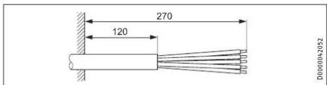
9.3 Preparing the connecting cables 19 - Installation 19
10.1 Water connection 19
10.2 Appliance installation 19
10.3 Power supply 20 - Commissioning 20
11.1 Commissioning 20
11.2 Recommissioning 20 - Settings 21
- Shutting down 21
- Troubleshooting 21
- Maintenance 22
15.1 Checking the safety valve 22
15.2 Draining the appliance 22
15.3 Checking / replacing the signal anode 22
15.4 Dcscaling 22
15.5 Anti-corrosion protection 22 - Specification 23
16.1 Dimensions and connections 23
16.2 Wiring diagrams and terminals 24
16.3 Heat-up diagram 25
16.4 Fault conditions 25
16.5 Details on energy consumption 25
16.6 Data table 26
GUARANTEE
ENVIRONMENT AND RECYCLING
SPECIAL INFORMATION
- The appliance may be used by children aged 3 and up and persons with reduced physical, sensory or mental capabilities or a lack of experience and know-how, provided that they are supervised or they have been instructed on how to use the appliance safely and have understood the resulting risks. Aged 3 to 8 years are only allowed to operate the tap connected to the appliance. Children must never play with the appliance. Children must never clean the appliance or perform user maintenance unless they are supervised.
- The connection to the power supply is only permissible as a permanent connection in conjunction with the removable cable grommet. Ensure the appliance can be separated from the power supply by an isolator that disconnects all poles with at least 3mm contact separation.
- Secure the appliance as described in chapters "Installation / Preparations" and "Installation / Installation / Appliance installation".
- Observe the minimum and maximum water inlet pressure (see chapter "Installation /Specification / Data table").
- Drain the appliance as described in the chapter "Installation / Maintenance / Draining the appliance".
Install a residual current device (RCD).
Sealed unvented operating mode:
- The appliance is under pressure. During the heat-up process, expansion water will drip from the safety valve.
- Regularly activate the safety valve to prevent it from becoming blocked, e.g. by limescale deposits.
- Install a type-tested safety valve in the cold water supply line. Please note that, depending on the static pressure, you may also need a pressure reducing valve.
- Size the drain so that water can drain off unimpeded when the safety valve is fully opened.
-
Fit the discharge pipe of the safety valve with a constant downward slope and in a room free from the risk of frost.
-
The safety valve discharge aperture must remain open to the atmosphere.
OPERATION
1. General information
The chapter "Operation" is intended for appliance users and qualified contractors.
The chapter "Installation" is intended for qualified contractors.

Note
Read these instructions carefully before using the appliance and retain them for future reference.
Pass on the instructions to a new user if required.
1.1 Safety instructions
1.1.1 Structure of safety instructions

KEYWORD Type of risk
Here, possible consequences are listed that may result from failure to observe the safety instructions.
Steps to prevent the risk are listed.
1.1.2 Symbols, type of risk
Symbol Type of risk

Injury

Electrocution

Burns
(burns, scalding)
1.1.3 Keywords
KEYWORD Meaning
DANGER Failure to observe this information will result in serious injury or death.
WARNING Failure to observe this information may result in serious injury or death.
CAUTION Failure to observe this information may result in non-serious or minor injury.
1.2 Other symbols in this documentation

Note
General information is identified by the symbol shown on the left.
Read these texts carefully.
Symbol Meaning

Material losses
(appliance, consequential and environmental losses)

Appliance disposal
This symbol indicates that you have to do something. The action you need to take is described step by step.
1.3 Units of measurement

Note
All measurements are given in mm unless stated otherwise.
2. Safety
2.1 Intended use
This appliance is designed to heat DHW. The appliance can supply one - or, in sealed unvented (pressurised) mode - several draw-off points.
This appliance is intended for domestic use. It can be used safely by untrained persons. The appliance can also be used in a non-domestic environment, e.g. in a small business, as long as it is used in the same way.
Any other use beyond that described shall be deemed inappropriate. Using the appliance for heating fluids other than water or for water supplemented with chemicals, such as brine, is also deemed inappropriate.
Observation of these instructions and of instructions for any accessories used is also part of the correct use of this appliance.
2.2 General safety instructions

WARNING Burns
During operation, the valve and safety assembly can reach temperatures in excess of 60^ .
There is a risk of scalding at outlet temperatures in excess of 43^ .

WARNING Injury
The appliance may be used by children aged 3 and up and persons with reduced physical, sensory or mental capabilities or a lack of experience and know-how, provided that they are supervised or they have been instructed on how to use the appliance safely and have understood the resulting risks. Aged 3 to 8 years are only allowed to operate the tap connected to the appliance. Children must never play with the appliance. Children must never clean the appliance or perform user maintenance unless they are supervised.

Material losses
Protect the water lines and the safety assembly against frost.

Note
Sealed unvented operating mode: The appliance is under pressure. During the heat-up process, expansion water will drip from the safety valve.
If water continues to drip when heating is completed, please inform your qualified contractor. Open vented operating mode: Whenever water is heated up, expansion water will drip from the spout.
2.3 Test symbols
See type plate on the appliance.
3. Appliance description
The appliance heats domestic hot water electrically, in line with the connected heating output. You can adjust the temperature using the temperature selector. Subject to the power supply, the water is automatically heated to the required temperature. The currently available heat content is displayed.
The appliance is suitable for both open vented (non-pressurised) and sealed unvented (pressurised) operation.
The internal steel cylinder is coated in special directly applied "anticor" enamel and equipped with a signal anode. The anode with consumption indicator protects the cylinder interior from corrosion.
3.1 Frost protection
The appliance is also protected against frost on the temperature setting "cold", as long as the power supply is guaranteed. The appliance switches on in good time and heats the water. The appliance does not protect the water supply lines and the safety assembly against frost.
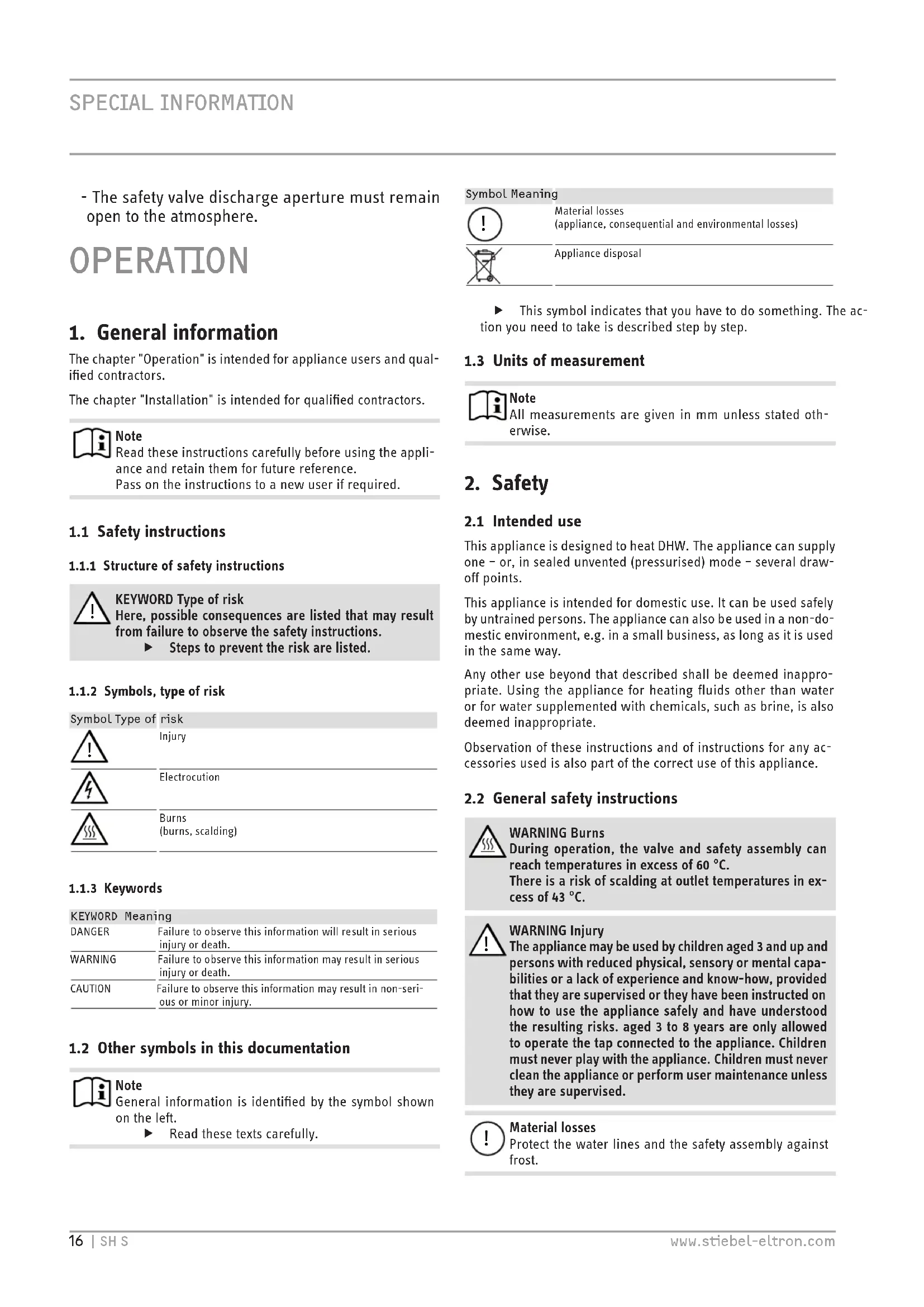
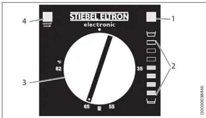
4. Settings
The temperature can be freely adjusted.
1 ON/OFF indicator
2 Heat content indicator
3 Temperature selector
4 SERVICE ANODE indicator
Cold
E Recommended energy saving position, low scaling, 60^
82°C Maximum temperature setting
Depending on the system, the actual temperatures may vary from the set value.
SERVICE ANODE indicator
Sealed unvented operating mode:

Material losses
Sealed unvented operating mode:
- Notify your qualified contractor if the SERVICE ANODE indicator illuminates.
Open vented operating mode:

Note
In open vented operation, the SERVICE ANODE indicator has no function.
Check the protective anode after the first 2 years of use and replace if necessary.
ON/OFF indicator
The ON/OFF indicator illuminates when water is being heated.
Heat content indicator
The display shows the currently available amount of mixed water at 40^ , with a cold water temperature of 15^ and a temperature setting of 65^ . The number of lights indicates the minimum available volume of mixed water at 40^ .
This enables you to match the temperature setting to your draw-off pattern to ensure optimum efficiency and save energy. We recommend you initially set the temperature to 65^ . If more than one indicator remains illuminated when your maximum draw-off volume is reached you can lower the set temperature.
| SH 30 S | 10 | 20 | 30 | 40 | 50 | 60 | 75 |
| SH 50 S | 13 | 30 | 45 | 65 | 80 | 100 | 125 |
| SH 80 S | 20 | 50 | 75 | 100 | 130 | 160 | 200 |
| SH 100 S | 25 | 60 | 90 | 130 | 160 | 200 | 250 |
| SH 120 S | 30 | 70 | 110 | 155 | 195 | 235 | 300 |
| SH 150 S | 40 | 90 | 135 | 190 | 240 | 295 | 370 |
| DHW demand, mixed water volume 40 °C | |||||||
| Bath | 120-150 | ||||||
| Shower | 30-50 | ||||||
| Hand washing | 2-5 | ||||||
5. Cleaning, care and maintenance
Have the electrical safety of the appliance and the function of the safety assembly regularly checked by a qualified contractor.
The signal anode must be replaced by the qualified contractor as soon as the SERVICE ANODE indicator illuminates (see chapter "Maintenance / Replacing the signal anode").
- Never use abrasive or corrosive cleaning agents. A damp cloth is sufficient for cleaning the appliance.
Scaling
Almost every type of water will deposit lime at high temperatures. This settles inside the appliance and affects both the performance and service life. The heating elements must therefore be descaled from time to time. A qualified contractor who knows the local water quality will tell you when the next service is due.
- Check the taps/valves regularly. You can remove limescale deposits at the spouts using commercially available descaling agents.
Regularly activate the safety valve to prevent it from becoming blocked, e.g. by limescale deposits.
6. Troubleshooting
| Problem Cause Remedy | ||
| The water does not heat up. | There is no power. Check the fuses/MCBs in your fuse box. | |
| The flow rate is low. | The aerator in the valve or the shower head is scaled up or contami-nated. | Clean and/or descale the aerator or shower head. |
| SERVICE ANODE indicator illuminates. | The signal anode needs replacing. | Notify your qualified contractor. |
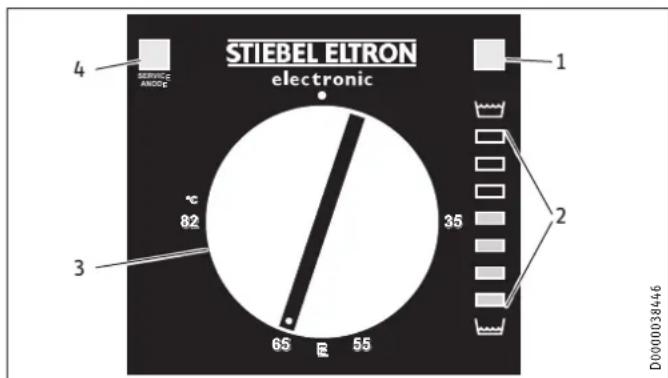
If you cannot remedy the fault, notify your qualified contractor. To facilitate and speed up your enquiry, please provide the serial number from the type plate (000000-0000-000000):
INSTALLATION
7. Safety
Only a qualified contractor should carry out installation, commissioning, maintenance and repair of the appliance.
7.1 General safety instructions
We guarantee trouble-free function and operational reliability only if original accessories and spare parts intended for the appliance are used.
7.2 Instructions, standards and regulations

Note
Observe all applicable national and regional regulations and instructions.
8. Appliance description
8.1 Standard delivery
The following are delivered with the appliance:
- Wall mounting bracket (2 pce for appliances with 120 l and 150 l nominal capacity)
- Spacers 5 mm (2 pce at the top / 2 pce at the bottom; for appliances with 120 l and 150 l, 4 pce at the top / 4 pce at the bottom)
Caps (2 pce)
Installation template
8.2 Accessories
Required accessories
Various safety assemblies are available for sealed unvented (pressure-tested) operation, depending on the static pressure. These type-tested safety assemblies protect the appliance against impermissible excess pressure.
Further accessories
Taps are available as accessories for open vented operation.
9. Preparations
9.1 Installation site
The appliance is designed for installation on a solid wall. Ensure the wall offers adequate load bearing capacity.
Always install the appliance vertically in a room free from the risk of frost and near the draw-off point.
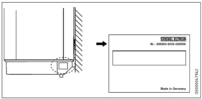
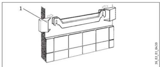
9.2 Fitting the wall mounting bracket
- You can use the installation template to transfer the dimensions to the wall.
- Drill the holes and secure the wall mounting bracket with screws and rawl plugs. Select fixing materials in accordance with the wall construction/condition.
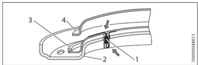
You can compensate for unevenness in the wall with the spacers provided.
Appliances with a nominal capacity of 120 l or 150 l require 2 wall mounting brackets.
1 Upper spacer
2 Lower spacer
9.3 Preparing the connecting cables
10. Installation
10.1 Water connection

Material losses
Carry out all water connection and installation work in accordance with regulations.
For sealed unvented (pressurised) operation, operate the appliance only with pressure-tested taps. For open vented (non-pressurised) operation, use non-pressurised taps. Connect the hydraulic connections with flat gaskets.
10.1.1 Permissible materials

Material losses
When using plastic pipework, observe the manufacturer's data and the chapter "Specification / Fault conditions". The temperature setting can be limited by the qualified contractor (see chapter "Settings / Limiting the temperature selection").
Cold water line
Galvanised steel, stainless steel, copper and plastic are approved materials.
A safety valve is required.
DHW line
Stainless steel, copper and plastic pipework are approved materials.
10.1.2 Sealed unvented (pressure-tested) for supplying several draw-off points
The max. permissible pressure must not be exceeded (see chapter "Specification / Data table" and cylinder specification).
Install a type-tested safety valve in the cold water supply line. Please note that, depending on the static pressure, you may also need a pressure reducing valve.
Size the drain so that water can drain off unimpeded when the safety valve is fully opened.
Fit the discharge pipe of the safety valve with a constant downward slope and in a room free from the risk of frost.
The safety valve discharge aperture must remain open to the atmosphere.
10.1.3 Open (non-pressurised) for supplying one draw-off point

Note
Never shut off the outlet and pivoting spout.
Do not use an aerator.
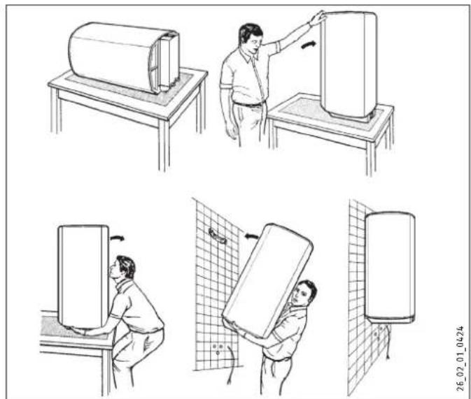
10.2 Appliance installation
Appliances with a nominal capacity of 120 l or 150 l require 2 people for installation.
1 Cap
Fit the caps.
10.3 Power supply

WARNING Electrocution
Carry out all electrical connection and installation work in accordance with relevant regulations.
Before any work on the appliance, disconnect all poles from the power supply.

WARNING Electrocution
The connection to the power supply is only permissible as a permanent connection in conjunction with the removable cable grommet. Ensure the appliance can be separated from the power supply by an isolator that disconnects all poles with at least 3mm contact separation.

WARNING Electrocution
Ensure that the appliance is earthed.

Material losses
Install a residual current device (RCD).

Material losses
Observe the type plate. The specified voltage must match the mains voltage.
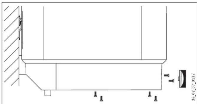
Pull off the temperature selector.
Undo the screws.
Remove the lower cap.
Pull the cable grommet out downwards while pressing on the locking hooks.
- Push the cable grommet over the connecting cable and snap the cable grommet back in place.
Connect the required load in accordance with the wiring diagrams (see chapter "Specification / Wiring diagrams and terminals").
Fit the lower cap.
Insert the screws.
Push on the temperature selector.
- Tick the selected connected load and voltage on the type plate with a ballpoint pen.
Sealed unvented (pressure-tested) operation
Connect the safety assembly to the appliance by screwing the pipes onto the appliance.
Open vented (non-pressurised) operation
Connect the appliance to the tap.
11. Commissioning
11.1 Commissioning
- Open a draw-off point until the appliance has filled up and the pipework is free of air.
Adjust the flow rate. For this, observe the maximum permissible flow rate with a fully opened tap (see chapter "Specification / Data table").
Sealed unvented (pressure-tested) operation: If necessary reduce the flow rate at the butterfly valve of the safety assembly.
Turn the temperature selector to maximum.
Switch the mains power ON.
Check the function of the appliance. Ensure that the thermostat switches off.
Sealed unvented (pressure-tested) operation: Check the function of the safety assembly.
11.1.1 Appliance handover
Explain the function of the appliance and safety assembly to users and familiarise them with their operation.
Make users aware of potential dangers, especially the risk of scalding.
Hand over these instructions.
11.2 Recommissioning
See chapter "Commissioning".
12. Settings
Limiting the temperature selection
You can adjust the temperature selection limit beneath the temperature selector.
Set the temperature selector to "cold" and isolate the appliance from the power supply.
Remove the temperature selector.
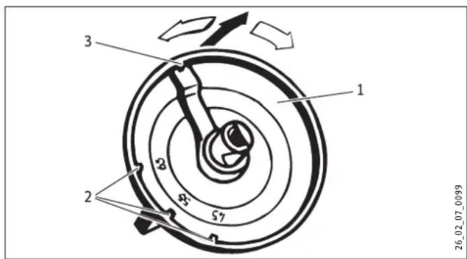
1 Temperature selector
2 Temperature selection limit at 45^ 55^ 65^
3 Factory setting 85^
Adjust the temperature selection limit.
Replace the temperature selector.
13. Shutting down
- Disconnect the appliance from the mains at the MCB/fuse in the fuse box.
- Drain the appliance (see chapter "Maintenance / Draining the appliance").
14. Troubleshooting

Note
At temperatures below -15^ the high limit safety cut-out may respond. The appliance may be subjected to these temperatures during storage or transport.
| Fault Cause | Remedy | |
| The water does not heat up. | The high limit safety cut-out has responded because the controller is faulty. | Remedy the cause of the fault. Replace the controller-limited com-bination. |
| The high limit safety cut-out has responded because the temperature has fallen below -15 °C. | Press the reset button (see diagram). | |
| The flanged immersion heater is faulty. | Replace the flanged im-mension heater. | |
| The safety valve drips when heating is switched off. | The valve seat is contam-inated. | Clean the valve seat. |
| SERVICE ANODE indicator illuminates. | The signal anode has been consumed. | Replace the signal anode. |
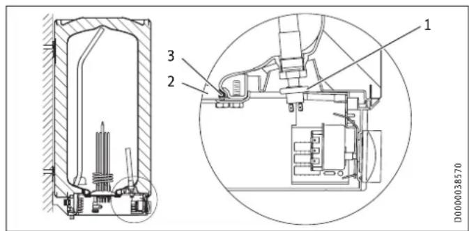
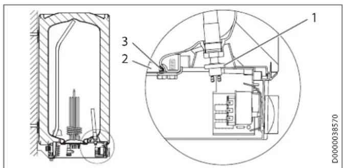
Reset key, high limit safety cut-out
The reset button is located behind the temperature selector.
Pull off the temperature selector.
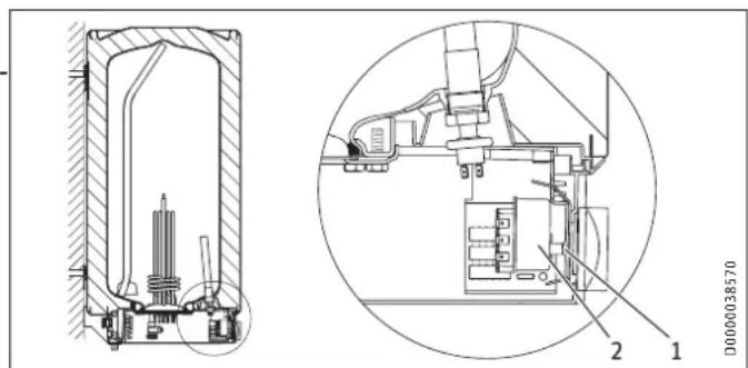
1 Reset key, high limit safety cut-out
2 Controller/limiter combination
15. Maintenance

WARNING Electrocution
Carry out all electrical connection and installation work in accordance with relevant regulations.
Before any work on the appliance, disconnect all poles of the appliance from the power supply.
For some maintenance work, the lower cap must be removed.
If you need to drain the appliance, observe chapter "Draining the appliance".
Note the insertion depths of the controller-limiter combination (see chapter "Specification / Dimensions and connections").
15.1 Checking the safety valve
Check the safety valve regularly.
15.2 Draining the appliance

WARNING Burns
Hot water may escape during the draining process.
If is necessary to drain the cylinder for maintenance or to protect the whole installation from frost, proceed as follows:
Close the shut-off valve in the cold water feed line.
Open the hot water taps on all draw-off points.
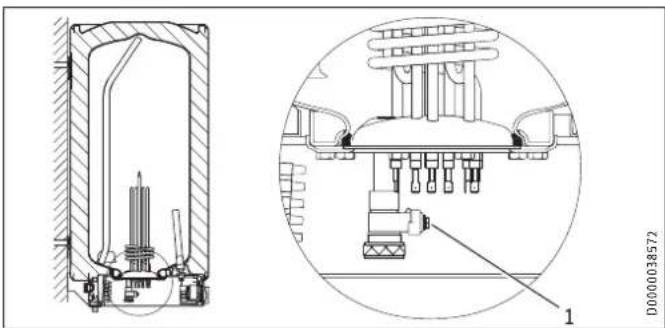
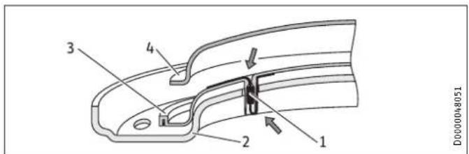
1 Drain valve with hose connection G 3/4
Undo the cap of the "drain" connection.
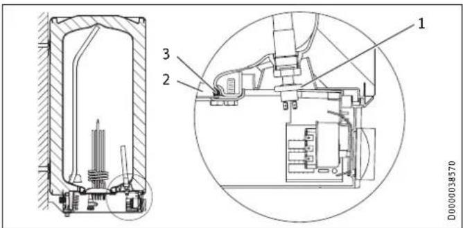
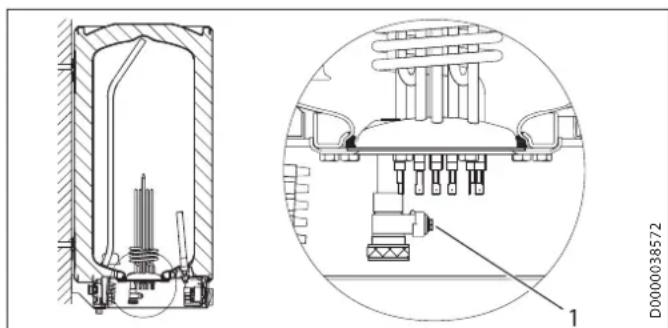
1 Pressure switch for signal anode
2 Flange plate
3 Seal ring
- When replacing the anode, take great care to fit the pressure switch on tightly.
Torque: 1^+0.5 Nm (tighten by hand)
15.4 Descaling
- Open vented operating mode: If you are using a mixer tap with a hand shower, regular descending will be necessary.
Only descale the flange after disassembly and never treat the cylinder surface or signal anode with descending agents.
15.5 Anti-corrosion protection
When carrying out service work, ensure that the anti-corrosion protection on the insulating plate is not damaged or removed. Reinsert the anti-corrosion protection correctly after replacement.
1 Anti-corrosion protection (390 Ω)
2 Pressure plate
3 Insulating plate
4 Flanged immersion heater
15.3 Checking / replacing the signal anode
If the SERVICE ANODE indicator illuminates, check the signal anode and replace if necessary.
SH 30 S (M 8)
Removed the flanged immersion heater to replace the signal anode.
SH 50 - 150 S (G 3 / 4
You can replace the anode without removing the flanged immersion heater.
16. Specification
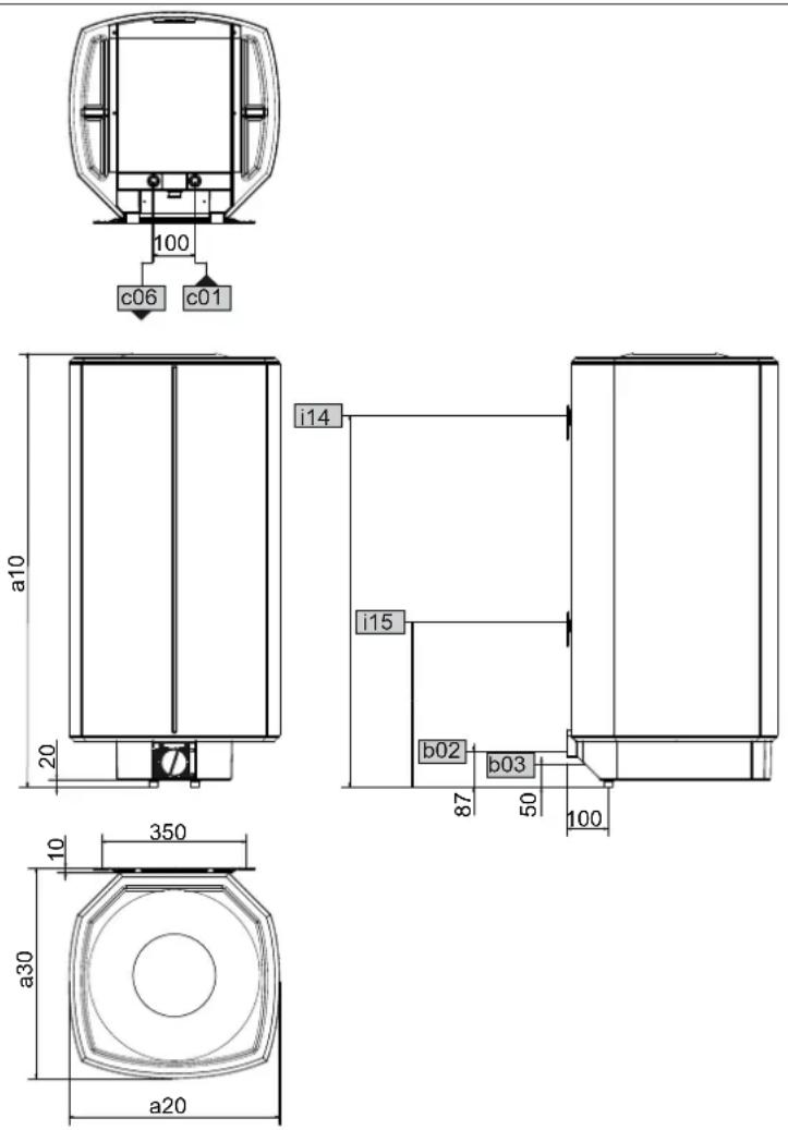
16.1 Dimensions and connections
D0000024799
| SH 30 S SH 50 S SH 80 S SH 100 | SH 120 S | SH 150 S | ||||||||
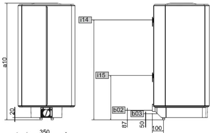
| a10 | Appliance | Height | mm | 770 | 740 | 1050 | 1050 | 1210 | 1445 | |
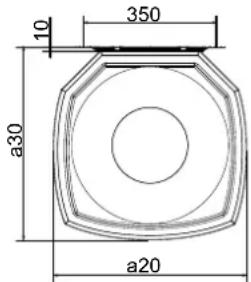
| a20 | Appliance | Width | mm | 410 | 510 | 510 | 510 | 510 | 510 | |
| a30 | Appliance | Depth | mm | 420 | 510 | 510 | 510 | 510 | 510 | |
| b02 | Entry electrical cables I | PG 21 | PG 21 | PG 21 | PG 21 | PG 21 | PG 21 | |||
| b03 | Entry electrical cables II | |||||||||
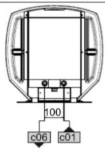
| c01 | Cold water inlet | Male thread | G 1/2 A | G 1/2 A | G 1/2 A | G 1/2 A | G 1/2 A | G 1/2 A | ||
| c06 | DHW outlet | Male thread | G 1/2 A | G 1/2 A | G 1/2 A | G 1/2 A | G 1/2 A | G 1/2 A | ||
| i14 | Wall mounting bracket I | Height | mm | 700 | 600 | 900 | 900 | 900 | 1100 | |
| Max. Ø fixing screw | mm | 12 | 12 | 12 | 12 | 12 | 12 | |||
| i15 | Wall mounting bracket II | Height | mm | 300 | 300 | |||||
| Max. Ø fixing screw | mm | 12 | 12 | |||||||
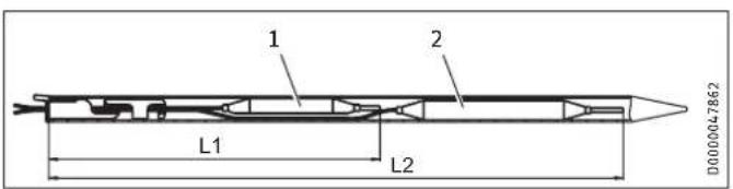
Controller-limiter combination immersion depths
1 Limiter sensor
2 Controller sensor
| SH30 S | SH50 S | SH80 S | SH100 S | SH120 S | SH150 S | ||
| L1 | Immersion depth | mm | 260 | 260 | 240 | 240 | 260 |
| L2 | Immersion depth | mm | 380 | 380 | 350 | 350 | 380 |
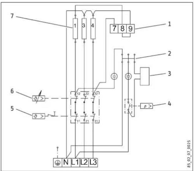
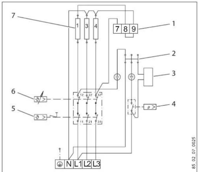
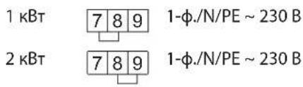
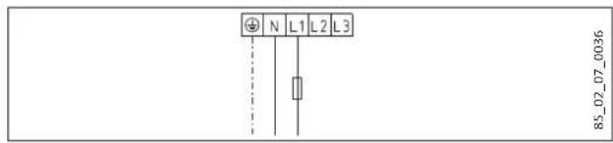
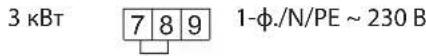
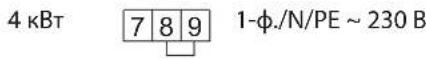
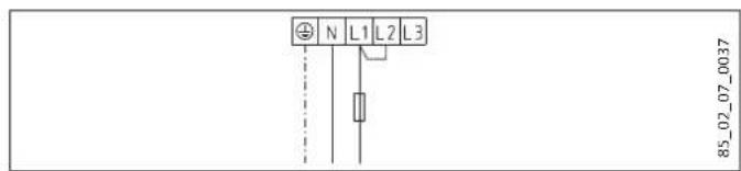
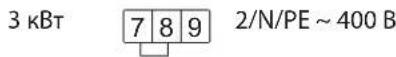
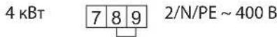
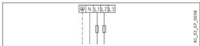
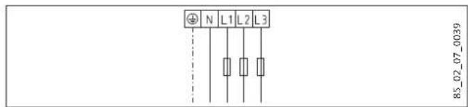
16.2 Wiring diagrams and terminals
1 Terminal for output changeover
2 Plug-in distributor for N conductor
3 Heat content indicator
4 Pressure switch for signal anode
5 High limit safety cut-out
6 Temperature controller
7 Heating element, 2kW 230V each
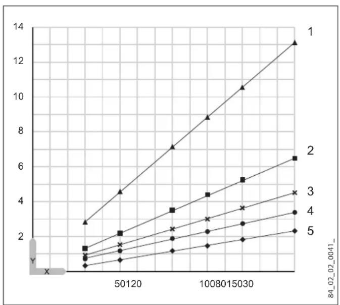
16.3 Heat-up diagram
The heat-up time depends on the cylinder capacity, cold water inlet temperature and heating output.
Diagram with 15^ cold water temperature:
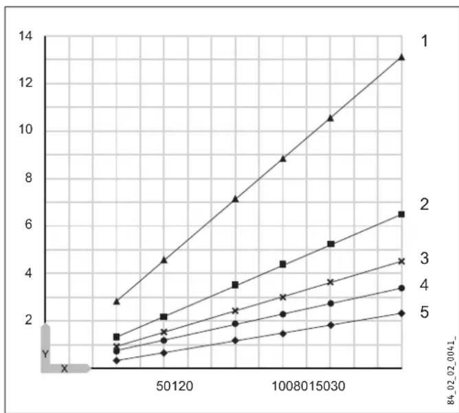
Set temperature setting 82^
X Nominal capacity [I]
Y Duration [h]
1 1 kW
22kW
3 3 kW
4 4 kW
56kW
16.4 Fault conditions
In the event of a fault, temperatures of up to 95^ at 0.6MPa can occur.
16.5 Details on energy consumption
Product datasheet: Conventional water heaters to regulation (EU) no. 812/2013 and 814/2013
| SH 30 S | SH 50 S | SH 80 S | SH 100 S | SH 120 S | SH 150 S | |
| 073047 | 073048 | 073049 | 073050 | 073051 | 073052 | |
| Manufacturer | STIEBEL ELTRON | STIEBEL ELTRON | STIEBEL ELTRON | STIEBEL ELTRON | STIEBEL ELTRON | STIEBEL ELTRON |
| Load profile | S | M | M | L | L | XL |
| Energy efficiency class | B | C | C | C | C | C |
| Energy conversion efficiency % | 36 | 38 | 37 | 38 | 38 | 39 |
| Annual power consumption kWh | 518 | 1349 | 1381 | 2666 | 2705 | 4321 |
| Default temperature setting °C | 60 | 60 | 60 | 60 | 60 | 60 |
| Sound power level dB(A) | 15 | 15 | 15 | 15 | 15 | 15 |
| Option for exclusive operation during off-peak periods | - | - | - | - | - | - |
| Smart function | - | - | - | - | - | - |
| Daily power consumption kWh | 2.437 | 6.233 | 6.419 | 12.288 | 12.516 | 19.859 |
| Amount of mixed water 40 °C l | 50 | 80 | 122 | 133 | 182 | 229 |
16.6 Data table
| SH 30 S SH 50 S SH 80 S SH 100 S | SH 120 S SH 150 S | |||||
| 073047 | 073048 | 073049 | 073050 | 073051 | ||
| Hydraulic data | ||||||
| Nominal capacity | I | 30 | 50 | 80 | 100 | 120 |
| Amount of mixed water 40 °C (15 °C/65 °C) | I | 59 | 97 | 159 | 198 | 235 |
| Electrical data | ||||||
| Connected load ~ 230 V | kW | 1-4 | 1-4 | 1-4 | 1-4 | 1-4 |
| Connected load ~ 400 V | kW | 3-6 | 3-6 | 3-6 | 3-6 | 3-6 |
| Phases | 1/N/PE, 2/N/PE, 3/N/PE | 1/N/PE, 2/N/PE, 3/N/PE | 1/N/PE, 2/N/PE, 3/N/PE | 1/N/PE, 2/N/PE, 3/N/PE | 1/N/PE, 2/N/PE, 3/N/PE | |
| Rated voltage | V | 230/400 | 230/400 | 230/400 | 230/400 | 230/400 |
| Frequency | Hz | 50 | 50 | 50 | 50 | 50 |
| Single circuit operating mode | X | X | X | X | X | |
| Application limits | ||||||
| Temperature setting range | °C | 35-82 | 35-82 | 35-82 | 35-82 | 35-82 |
| Max. permissible pressure | MPa | 0.6 | 0.6 | 0.6 | 0.6 | 0.6 |
| Test pressure | MPa | 0.78 | 0.78 | 0.78 | 0.78 | 0.78 |
| Max. permissible temperature | °C | 95 | 95 | 95 | 95 | 95 |
| Max. flow rate | l/min | 18 | 18 | 18 | 18 | 18 |
| Min. water inlet pressure | MPa | 0.1 | 0.1 | 0.1 | 0.1 | 0.1 |
| Max. water inlet pressure | MPa | 0.6 | 0.6 | 0.6 | 0.6 | 0.6 |
| Min./max. conductivity, drinking water | μS/cm | 100-1500 | 100-1500 | 100-1500 | 100-1500 | 100-1500 |
| Energy data | ||||||
| Standby energy consumption/24 h at 65 °C | kWh | 0.46 | 0.54 | 0.67 | 0.86 | 0.99 |
| Energy efficiency category | B | C | C | C | C | |
| Versions | ||||||
| IP rating | IP25 | IP25 | IP25 | IP25 | IP25 | |
| Sealed unvented type | X | X | X | X | X | |
| Open vented type | X | X | X | X | X | |
| Colour | White | White | White | White | White | |
| Dimensions | ||||||
| Height | mm | 770 | 740 | 1050 | 1050 | 1210 |
| Width | mm | 410 | 510 | 510 | 510 | 510 |
| Depth | mm | 420 | 510 | 510 | 510 | 510 |
| Weights | ||||||
| Weight, full | kg | 53 | 78 | 118 | 140 | 165 |
| Weight, empty | kg | 23.1 | 28 | 38 | 40.8 | 45.5 |
Guarantee
The guarantee conditions of our German companies do not apply to appliances acquired outside of Germany. In countries where our subsidiaries sell our products a guarantee can only be issued by those subsidiaries. Such guarantee is only granted if the subsidiary has issued its own terms of guarantee. No other guarantee will be granted.
We shall not provide any guarantee for appliances acquired in countries where we have no subsidiary to sell our products. This will not affect warranties issued by any importers.
Environment and recycling
- Dispose of the appliances and materials after use in accordance with national regulations.
If a crossed-out waste bin is pictured on the appliance, take the appliance to your local waste and recycling centre or nearest retail take-back point for reuse and recycling.
This document is made of recyclable paper.
- Dispose of the document at the end of the appliance's life cycle in accordance with national regulations.
REMARQUESPARTICULIERES
UTILISATION
m = 311
13/14
A DEPOSER
EN MAGASIN
u
( xt^2 + x) - 4( xt^2 + x) ( -3) = 0
A DEPOSER
EN DECHETERIE
= 12( 2 + + ) ^2 - 1m( ^2 + ^2 - ^2)
WAARSCHUWING verbranding
WAARSCHUWING verbranding
SH 50 - 150 S (G 3 / 4
U kurz de anode verrangen zonder de verwarmingsflens te demonteren.
X Nominate inhoud [I]
Y Duur [h]
Heo6xOIMOBHIMATEbHO npouHTaTb TEKCTbI yka3AHn.
CNMBOJ
3haueHne

MaTePnAaBHy yuep6 (NoBpeXeHne 06OpyDObAHna, KocBeHHb yuep6 uyuep6 dny OkpyKaiooJe Cpebl)

Yttnn3aunyycptpoctBa
3TOT CmB0J yKa3bIbaeHT Ha Heo6xOJIMMOCTb BbIOJIHeHn ONpeJeHnBIX DeiCTBn. OncaHne Heo6xOJIMbIX DeiCTBn PnPBeJeHO Wa 3a WaROM.
1.3 EdnHnCbI n3MepeHnA

Yka3aHne
Ecn He yka3aHO uHoe, Bce pa3MepbI npNBedeHbI B MnnnMeTpax.
2. TexHnka 6e3OnacHOCTN
2.1 NcnoJb3ObaHHe no Ha3HaueHnIO
Pnp6op npedha3nueH nla HarpBa BODonpoBOnHO Bobl. Pnp6op MoKeT o6cnyKuBaTb OHy, a npn EKnpyaTuN B 3aKpbITOM (HaOpHOM) pexkme - HeckoIbKO ToeK OT6opa.
-Приборпразнаначehдя 6ытOBОги NCПОьБЗВАн.Дя ero 6e3ОпалснохогообслУЖИВAHЯ NOЛБСОВATEH He Tpe6уETca npoxOДТь nHCTpyKТж.Bo3MOxHNo NCПОьБЗВАне рпбор He TOLьКВ 6bIty, Ho N, HApPIMep, Ha ppeNpRnTnxM Manoro 6u3HeCa пи уCNOBи CO6JIQUDEHЯ Tex Xe yCNOBи AkCnIy- ataци.
HIO6oe HHOe Hn He yka3aHHoe B HactoIeM pyKOBODCTBe NCNOb3OBAHHe DaHHoro YcTPOJCTBa CHTaETcN CNOb3OBAHHe Me No Ha3HaueHIno. NcNOb3OBAHHe Me No Ha3HaueHIno CHTaETcTaTke NcNOb3OBAHne np6opda nHaRpeBa
IIO6bIX dpyrnx KxuKoCTe KpOme BObl, a TaKke HarpeB BObl Cdo6abHeHem XmMknAaHnPumep, paccola.
NcnoB3ObaHne no Ha3HaueHnIO NOpa3ymeBaet TaKke co6IIOeHne Tpe6oBaHH NaCTOJe rpykoBOdCTBa, a TaKxepykoBOdCTB K IcNoJIb3yEmbIM npHaADJnxHOCTAM.
2.2 06uye yka3aHnno TeXnKe 6e3onacHOCTn

IPENyIPEKDEHNE oxor
Bo Bpempa60bApMaTpynnpaHHTenbHa rpynnma MoryT HarpeBaTbcn DO TemnepaTypb CbbIe 60°C.
Pn TemnepaType BObl Ha BbIXOe Bblue 43 ^ C cyueCTByET ONaCHOCTb OBapuBaHn.

PENEUYIPEXJEHNE TpaBMa
IeTAM CTAPWE 3 let, a TAKKHe NnUaM C orpaHnueHbIMn fN3nuecknM, ceHCOPHBIMn yMCTBENHbIMn cNoC6hOCTaMn, He IMeIOUm ONbTa n He BnAdeIOUIm INoOpMaunne O npu6ope, pa3peSeHoNCNOBtB npu6op ToBko NO pncMOrpoM Dpyrnx IINu nn NoCNE COOTBeTCTByoUero INCHpykTaKa o npabunax 6e3OnaCHO rONb3OBaHN u NOTeHuaNbHO onACHOCTN B Cnyae HecO6NIOJeHNr Etnx npabUN. DeTAM B BO3pacte ot 3 do 8 let pa3peWaaETcNAb3OBaTbCA TObKO cmecnteMe, NOdKNIOUeHHbIM K npu6opy. He donyckatb wanoCTeDeTe c npu6opom. DeTu MOry BBInONHrTa uNCTky npu6opa n Te BnDbI TexHnueCKoro 06cnykBaHNu, KOtOpbie O6bHuO npou3BOaTcR naB3OBaTeMe, ToBko NO pncMOrpoM B3Pocnbix.

MaterpnaIbHbIy uIep6
BoonpoBOD n npdeoxpaHnteNbHa rpynnn daJxHb6bTb 3aunueHb ot 3aMeP3aHn noIb3ObaTeNeM.

Yka3aHnE
Pn6op 3akpbitoro Tuna: np6op HaxoHCTnoDabJeHem. Bo Bpemr HarpeBa BOa BCneCTBue TeNIOBORO pacuHpeHn KaetaT n peoxpaHHTeJbHorO Klanha.
EcnnoOKOHAHnHarpeBa BOa no-npexHemy
IoKanbBaET, Heo6xOdmo COo6uNTb 06 3TOM CneunnaNCTy.
Pn6op OTKpbIToR Tnna: npn KaXdOM HArpeBaHn paunpOuaaB Oda KaNaET B MeCTe CnBa.
2.3 3HaK TexHnueckOro KOHTpOJIa
Cm.3aOoDcky Ta6nUky Ha np6ope.
Ebp3Mckoe COOTBETCTBNE
DAHnI npn6op cooTBeCTbYET Tpe6oBaHnIe 6e3oNaChOCTn Texnuecknx peIamEnTOB EbpazniCKoro 3koHOMueckoro Coio3a TP TC 004/2011, TP TC 020/2011 n npoiouen cooTBeCTbYU OIOne npOeUpybI NOITBePjKeHncooTBeCTBn. CepTNΦKaT cooTBeCTBnN NO TC RU C-DE.AR46.B.84155, cpoK deiCTBnC 21.02.2018 r. no 20.02.2023 r. Opran no cepTNΦKauIN «POCTECT-MockBA» AO «PernoHaJIbHbI oprah no cepTNΦKaauIn n TeCTnIpoBaHnIO>.
3.Опсане устpoиства
Pnp6op npedctabnaret c06o3neKtpnueeckn HarpBaTeIb BODONPOBDOHO B0dbI C pexkIMOM cTahnapTHoro HarpBeA. Tempepatya 3aadaetcpeyIaTOPOM Tempepatby. ABtOMaTueckn HarpeB DO HxHNO TEmpepatpyI npOn3BOUInTCB 3aBNCUMOCTN OT 3eKTPoCHA6KeHn. Ha dncnnee oTo6paxaETCn DOCTynhbo O6bem ropaye BObl.
MooKET 3KcNJIyATnIPOBaTbCk Ka npu6Op OTkpBtORO (6e3Ha-nOPHoro), TaK n 3AkpyItoro (HanopHoro) Tnna.
CtaIbHOB BHyTpEHHN 6aK IMeET CneuaJIbHoe 3MaIeBoe NOKpbITNE «anticor» n OCHaueH CNrHaJIbHbIM aHOJOM. AHOc c HnDnKaTOpOM n3Hoca o6ecneuBaet 3aunTy BHyTpEHHero 06bema pe3epByapa ot KoppoHN.
3.1 PexkM 3aunTbI OT 3amep3aHnA
Pn6bOp 3aunuH eOH 3amep3aHnRA TAKKe npu yctahOBke peryIaTopa TemnepaTpby Ha XoNoDHO, HO nIra 3TOr OH dONKeH 6bIb NODKIIouen K CETn 3neKtponitAHn. Pn6bOp CBOBpeMeHHO BkUOaETcN HArpeBaET BOy. Pn6bOp He 3aunuaeTrpy6bI BOOnpOBOda N PpeDOxpaHTeNbHbIKOMnNEKT OT 3amep3aHnR.
4. Hactpoikn
PerynipobkA TemnepaTpybI npOn3BOuNTc6ecctyneHauTo.
1 CnHnBna JAmna HnDnKaun pa6oeryo pexmna
KpeCTIKOM BbI6paHHyIO IJIa NODKIIOueHnma MoUHOCTb HnapJxKeHne.
Pn6op 3akpbitoro (HanopHoro) Tuna
CoeunHntb npedoxpaHnteBHy bY3en c np6opom, nCnOJb3y dI KpENHeH Tpy6 pe3b6OBoE coeHNHeHne.
Pn6op oTKpbIToro (6e3HanopHoro) Tuna
PnBnHTb apMaTpy K np60py.
Pn onpeJeHbIx pa6oTax no Texo6cnyxuBaHnHO Heo6xoDnMo CHMaTb HxKHiO KpbIiKy.
Ecn Heo6xOJIMO OOnopKHNb npn6Op, Heo6xOJIMO cneioBaTb yka3aHnM rnaBbl «OnopKHeHne npn6opa>.
CneObaTb yka3aHbIM 3HaueHnM rny6uHbI nOrpyKeHnKOM- 6uHnpOBaHHoro yCTpoiCTBa «peryIaTOp-orpaHnUHTeIb» (CM. rnaBy «TexHnueckne xapaKTePncTnKn / Pa3mpeBn coeHnHeHnA»).
14.1 Поверка пpeохсаньног КлanaHa
PerynepHO BbINHrTb npOBepky npedoxpaHntbHoroklananaHa.
14.2 OnopoxKHeHne np6opa

PENEYNPEKDEHNE oxor
PnOnopOxHeHn Pnp6opa n3 Hero MoKet BbITEKaTb ropya BOa.
Ecni Ia TeXo6CnyKuBaHnI nn 3aunTbI BceY uCTaHOBKn OT 3amep3aHnHyxHo npOn3BeCTn CInB BOdbI,TO Heo6xoJIMO BblONHHTcNeDyUOJIne WArN:
3aKpbIb 3aOpHbI BcHTnIb B Tpy6OpPoBoe nOaU XoJIoHOH BObl.
OTkpblb KpaHbI ropueyB BObl BO BCex Tockax OT6opa
1 CInBHOB BENTINb CO WTyepoM dIa IuaHaRa G 3/4
OTBepHyTb KpbIiKy co CnIBHOro naTp6Ka.
14.3 NpOBePkA / 3aMeHa cHrHaJIbHOro aHOJa
PpOBepnB CnHbHbAHOJ pNp BKNIOeHN CnHaB-HoI JAMnbl《SERVICE ANODE》(TEX05CJIYKINBAHNE AHODA》,npu Heo6xOaMOCt N BInOnHHTb erO 3ameHy.
SH 30 S (M 8)
ДяЗamehbCINHaJIbHOro aHOJa Heo6XoIMO demOHn-POBaTbФaHeuC HArpeBaTeNbHbIM THom.
SH50-150S (G3 / 4)
3aMeHHTb aHOJ MOXHO 6e3 demoHTaxka fHaHua c HarpeBaTeJIbHbIM T'Hom.
1Пневматческий ВьклочателдгсганьHoro aHODa
2 ΦnauHaeBa nlaactHa
3 YnIOIeHInTeBHOe KOnbO
Pn 3aMeHe aHOna HxKHO 6o3aTeNbHO CneIHTb 3a TEM, TTO6bl NHeBMAtuYeCKN BbIKIOUaTeNb 6bl nPnBepHyT repMeTuHO.
Momet 3aTJKKn:1 ^+0,5 Hm (BpyHyIO)
14.4 YdaJIeHne HAKnN
Pn6op OTKpbITo rTna: Pn nCnoB3ObaHnn CmecnteJc pyHbIM dywem Heo6xOaHMo peryIaRHO ydaJIaTb N3-BECTKOBbH HaneT.
YdaJIaTb HaKInb C cIaHaCt TOnbKO nOcIe erO demoHTaKa, He 6pa6aTaBbA Tb CpeDCTBaMn Ira ydaJeHnHaKInn NO-BepxHOCTb 6aKa NcHHaJIbHbI aHOd.
14.5 PokpbItne dIJI 3aunTbI OT Koppo3n
PpOBepntb, yTO6bl npTexHnueckOM o6cnykBaHN Ha n3OlnpyuOe naHeI N He 6bl NOBpeJdeH nn ydaJIe H aHTNKoppo3NoHHb pe3NCTOp. HAnEkaUIM O6pa3OM BOCCTaHOBNb 3aunTHoe NOKpbITne npOTNB Koppo3H NocNe 3aMeHbl.
1ANTKoppo3nOHbI pe3nCTop (390OM)
2 Pnpxmmna naHeB
3 I3oIpyuOa npHeB
4 Φlaheu c harpeBaTeIbHbIM THom
15. Texhnueckne xapaKTepeNCTnKN
15.1 Pa3mepbI n coeMHHeHnA
| SH 30 S SH 50 S SH 80 S SH 100 S SH 120 S SH 150 S | ||||||||
| a10 | Прибор | Высota | MM | 770 | 740 | 1050 | 1050 | 1210 |
| a20 | Прибор | ШирINA | MM | 410 | 510 | 510 | 510 | 510 |
| a30 | Прибор | Глбиha | MM | 420 | 510 | 510 | 510 | 510 |
| b02 | Ввдддддддддддддддддддддддддддддддддддддддддддддддддддддддддддддддддддддддддддддддддддддддддддддддддддд徳 | PG 21 | PG 21 | PG 21 | PG 21 | PG 21 | PG 21 | |
| b03 | Ввдддддддддддддддддддддддддддддддддддддддддддддддддддддддддддддддддддддддддддддддддддддддддддддддд徳 | |||||||
| c01 | Повдддддддддддддддддддддддддддддддддддддддддддддддддддддддддддддддддддддддддддддддддддддддддддддддддддد | Hаржная рezьба | G 1/2 A | G 1/2 A | G 1/2 A | G 1/2 A | G 1/2 A | G 1/2 A |
| c06 | Быпск. Trуба رорочь вовы | Hаржная рezьба | G 1/2 A | G 1/2 A | G 1/2 A | G 1/2 A | G 1/2 A | G 1/2 A |
| i14 | Планka дд д д дд дд d d d d d d d d d d d d d d d d d d d d d d d d d d d d d d d d d d d d d d d d d d d d d d d d d d d d d d d d d d d d d d d d d d d d d d d d d d d d d d d d d d d d d d d d d d d d d d d d d d d d | Высota | MM | 700 | 600 | 900 | 900 | 900 |
| Мakс. Диаметр крөного ВИNTA | MM | 12 | 12 | 12 | 12 | 12 | ||
| i15 | Насенья мontайная планka II | Высota | MM | 300 | ||||
| Мakс. Диаметр крөного ВИNTA | MM | 12 | ||||||
MOHTAK
TexHnueckne xapaKTepeNCTnKN
Kom6nHaqna «peryIaTOp-orpaHmUteNb», rny6nHa norgyKeHn

1 DaTnK OpraHnUteIa
2ДатчкperynЯтopa
| SH | 30 S | 50 S | 80 S | 100 S | 120 S | 150 S | ||
| L1 | Глобина пору-жения | MM | 260 | 260 | 240 | 240 | 240 | 260 |
| L2 | Глобина пору-жения | MM | 380 | 380 | 350 | 350 | 350 | 380 |
15.2 3neKtpnueckn cXeMbIn coeHHeHnA
1 Klemma nna nepekeKIOueHnro MOUHOCTN
2UTekehbu coeHHntb nHyeBOr npoBoa N
3 INHdkatop doctynHoro oBbema ropaye BOdb
4 THEBMaTnueckn BbIKNIOuTaTeNb dIra CnHrHaBHO r aHOda
5 PpeoXpaHnteBHybOrgaHnHTeB Temnepeatypbl
6 Perynatop TemnepaTpybI
7 HarpeBaTeBbHbIe 3neMeHTbI NO 2 KBT, 230 B
15.3ДиагамmaHarpeBa
Динтьнocь HarpeBa 3abnCIT OT EmKoCTn pe3epByapa, TempepaTpybI XOLOHOBdBi N MOUHOCTN HarpeBa.
DiarpammaHarpeBa npu TemnepaType xoJIoHNoB BoIb 15 ^ C
HactpoKa 3aHaHHoTempeaTypbI 82°C
X HomHaJIbHaB BMECTIMOCTb [J]
YДиNTeNbHOCTb[4]
1 1 KBT
2.2 KBT
3 3 kBt
4 4 kBt
56KBT
15.4 Bo3MOxHbIe HcnpaBHOCTn
Pn HeucnpaBHOCTu Tempeatypa npu 0,6 MNa MoKet NOBbIwaTbcra do 95^
15.5 XapaKTePncTnK n3HeprnoTope6neHn
TexHnueckne xapaKTepeNCTNK n3dEJIa: CtaHdapTHbI BDOHOarpeBaTeJIb (B COOTBeTcTBUN c perJameHOM EC Ng 812/2013 | 814/2013)
| SH 30 S | SH 50 S | SH 80 S | SH 100 S | SH 120 S | SH 150 S | ||
| 073047 | 073048 | 073049 | 073050 | 073051 | 073052 | ||
| Пюизвodи龟ь | STIEBEL ELTRON | STIEBEL ELTRON | STIEBEL ELTRON | STIEBEL ELTRON | STIEBEL ELTRON | STIEBEL ELTRON | |
| Пюофиль Нагузkin | S | M | M | L | L | XL | |
| Клascьнисторддговпспьбштчы龟ь | B | C | C | C | C | C | C |
| Знергетшиеский КПД | % | 36 | 38 | 37 | 38 | 38 | 39 |
| Гововские по trade ленице щеktroэнергий | kWh | 518 | 1349 | 1381 | 2666 | 2705 | 4321 |
| Заданая на захode TemпераTypeа | °C | 60 | 60 | 60 | 60 | 60 | 60 |
| Уровень звековский мошноctn | ДБ(A) | 15 | 15 | 15 | 15 | 15 | 15 |
| Возможность леслиayaразс铝合金 NCKЛочтельно | - | - | - | - | - | - | - |
| В п��iodы НИЗКОнагузkin | |||||||
| Фунkedу Smart | - | - | - | - | - | - | |
| Сточhoe по trade ленице щеktroэнергий | kWh | 2,437 | 6,233 | 6,419 | 12,288 | 12,516 | 19,859 |
| Оьем смендань Вобdi 40 °C | I | 50 | 80 | 122 | 133 | 182 | 229 |
MOHTAK
TexHnueckne xapaKTepeNCTnKN
129343, r. MockBa, Poccn
15.6 Ta6nua napaMeTPOB
| SH 30 S SH 50 S SH 80 S SH 100 S SH 120 S SH 150 S | 073047 | 073048www.stiebel-eltron.ru073049www.stiebel-eltron.ru | 073050 | 073051 | 073052 | |
| ГиравлиескихарakтерICTКИ | ||||||
| Hominahьая EMKOSTb | I | 30 | 50 | 80 | 100 | 120 |
| Оьем смешаимов Bodь 40 °C (15 °C / 65 °C) | I | 59 | 97 | 159 | 198 | 235 |
| ЗлектуескихарakтерICTКИ | ||||||
| Подknюаемая мошноctь ~ 230 B | KBТ | 1-4 | 1-4 | 1-4 | 1-4 | 1-4 |
| Подknюаемая мошноctь ~ 400 B | KBТ | 3-6 | 3-6 | 3-6 | 3-6 | 3-6 |
| Фазы | 1/N/PE, 2/N/PE, 3/N/PE | 1/N/PE, 2/N/PE, 3/N/PE | 1/N/PE, 2/N/PE, 3/N/PE | 1/N/PE, 2/N/PE, 3/N/PE | 1/N/PE, 2/N/PE, 3/N/PE | |
| Hominahьhoe habражениe | V | 230/400 | 230/400 | 230/400 | 230/400 | 230/400 |
| Частоа | Гц | 50 | 50 | 50 | 50 | 50 |
| Одноконту新股им | X | X | X | X | X | |
| ПробныRobочero дanaээээээээээээээээээээээээээээээээээээээээээээээээээээээээээээээээээээээээээээээээээээээээээээээээээээн | ||||||
| Диапазон permулковук Tempeратуры | °C | 35-82 | 35-82 | 35-82 | 35-82 | 35-82 |
| Мамс. дорстиме давелениe | Mпa | 0,6 | 0,6 | 0,6 | 0,6 | 0,6 |
| Искытalemьhoe давелениe | Mпa | 0,78 | 0,78 | 0,78 | 0,78 | 0,78 |
| Мамс. дорстима Tempeратура | °C | 95 | 95 | 95 | 95 | 95 |
| Мамс. расхod | л./мин | 18 | 18 | 18 | 18 | 18 |
| Мин. давеление Bodь на Вхode | Mпa | 0,1 | 0,1 | 0,1 | 0,1 | 0,1 |
| Мамс. давеление Bodь на Вхode | Mпa | 0,6 | 0,6 | 0,6 | 0,6 | 0,6 |
| Мин./мамс. ладостриповindость Bodopровodnotь Bodopro- Bodь | μS/cm | 100-1500 | 100-1500 | 100-1500 | 100-1500 | 100-1500 |
| ЗнэретческихарakтерICTКИ | ||||||
| Расхов д лергеля в ржиме ожidiанna / 24 chasyни 65 °C | KBТ/ч | 0,46 | 0,54 | 0,67 | 0,86 | 0,99 |
| Клас сөргөдөдөдөдөдөдөдөдөдөдөдөдөдөдөдөдөдөдөдөдөдөдөдөдөдөдөдөдөдөдөдөдөдөдөдөдөдөдөдөдөдөдөдөдөдөдөдөдөдөдө徳 | B | C | C | C | C | |
| Мошидацции | ||||||
| Стениь зашиты (IP) | IP25 | IP25 | IP25 | IP25 | IP25 | |
| Конструцnia зakрытого Тпа | X | X | X | X | X | |
| Конструцnia оTKрытого Тпа | X | X | X | X | X | |
| Цvet | белBI | белBI | белBI | белBI | белBI | |
| Разmersы | ||||||
| Высota | MM | 770 | 740 | 1050 | 1050 | 1210 |
| ШирINA | MM | 410 | 510 | 510 | 510 | 510 |
| Глбуна | MM | 420 | 510 | 510 | 510 | 510 |
| Вес | ||||||
| Вес заоленного прибopa | Кг | 53 | 78 | 118 | 140 | 165 |
| Вес поожné орибopa | Кг | 23,1 | 28 | 38 | 40,8 | 45,5 |
CepinHbHomep Ha uNbDnke np6opa coepxnt DaTy n3roTOB- leHn np6opa.
CepinHbHomep nMeet cIeDyIOU cyCTpykTypy: 6-3HaHbH apTNKyn npi6opa - 4-3HaHnA daTa npOn3BOcTba- 6-3HaHbN nopRd-KOBbHOMep.
4-3HaHnJa DaTa Ipon3BODCTBa paCUnIΦpOBBbAeTc TaK:
-Первье ДBE ue nФрbl ПлUC 25 -То ГД ИЗгOTOBENHЯ пибopa (2цнфы),Toecb 94+25->ДЯ 2019,93+25->ДЯ 2018ИТаКдалee;
IocneHnE DBe UINpMb MInHyc 25-TO KaJIeHApHa HeJeIa n3- roToBNeHn np6opa.
Hanpimep,4-3HaHnAa DaTa npou3BOndBa 9440 cooTBeTCTByeT 15 HeJeB E 2019 roy.
U3ROTOBNTeIb:
SH 50-150 S (G 3 / 4
- INSTALLATION
- Sicherheit
- GUARANTEE
- ENVIRONMENT AND RECYCLING
- SPECIAL INFORMATION
- Sealed unvented operating mode:
- OPERATION
- General information
- Note
- Safety instructions
- Structure of safety instructions
- KEYWORD Type of risk
- Symbols, type of risk
- Keywords
- Other symbols in this documentation
- Units of measurement
- Safety
- Intended use
- General safety instructions
- WARNING Burns
- WARNING Injury
- Material losses
- Test symbols
- Appliance description
- Frost protection
- Settings
- SERVICE ANODE indicator
- ON/OFF indicator
- Heat content indicator
- Cleaning, care and maintenance
- Scaling
- Troubleshooting
- Safety
- General safety instructions
- Instructions, standards and regulations
- Appliance description
- Standard delivery
- Accessories
- Required accessories
- Further accessories
- Preparations
- Installation site
- Fitting the wall mounting bracket
- Preparing the connecting cables
- Installation
- Water connection
- Permissible materials
- Cold water line
- DHW line
- Sealed unvented (pressure-tested) for supplying several draw-off points
- Open (non-pressurised) for supplying one draw-off point
- Appliance installation
- Power supply
- WARNING Electrocution
- Sealed unvented (pressure-tested) operation
- Open vented (non-pressurised) operation
- Commissioning
- Commissioning
- Appliance handover
- Recommissioning
- Settings
- Limiting the temperature selection
- Shutting down
- Troubleshooting
- Reset key, high limit safety cut-out
- Maintenance
- Checking the safety valve
- Draining the appliance
- Descaling
- Anti-corrosion protection
- Checking / replacing the signal anode
- Specification
- Dimensions and connections
- Heat-up diagram
- Fault conditions
- Details on energy consumption
- REMARQUESPARTICULIERES
- UTILISATION
- WAARSCHUWING verbranding
- EdnHnCbI n3MepeHnA
- TexHnka 6e3OnacHOCTN
- NcnoJb3ObaHHe no Ha3HaueHnIO
- 06uye yka3aHnno TeXnKe 6e3onacHOCTn
- IPENyIPEKDEHNE oxor
- PENEUYIPEXJEHNE TpaBMa
- MaterpnaIbHbIy uIep6
- Yka3aHnE
- 3HaK TexHnueckOro KOHTpOJIa
- 3.Опсане устpoиства
- PexkM 3aunTbI OT 3amep3aHnA
- Hactpoikn
- Pn6op 3akpbitoro (HanopHoro) Tuna
- Pn6op oTKpbIToro (6e3HanopHoro) Tuna
- Поверка пpeохсаньног КлanaHa
- OnopoxKHeHne np6opa
- NpOBePkA / 3aMeHa cHrHaJIbHOro aHOJa
- YdaJIeHne HAKnN
- PokpbItne dIJI 3aunTbI OT Koppo3n
- Texhnueckne xapaKTepeNCTnKN
- Pa3mepbI n coeMHHeHnA
- MOHTAK
- TexHnueckne xapaKTepeNCTnKN
- Kom6nHaqna «peryIaTOp-orpaHmUteNb», rny6nHa norgyKeHn
- 3neKtpnueckn cXeMbIn coeHHeHnA
- 15.3ДиагамmaHarpeBa
- Bo3MOxHbIe HcnpaBHOCTn
- XapaKTePncTnK n3HeprnoTope6neHn
Brand : STIEBEL ELTRON
Model : SH 80 S
Category : Boiler