
EFX 30.1 2HT - Cooker TEKA - Free user manual and instructions
Find the device manual for free EFX 30.1 2HT TEKA in PDF.
Download the instructions for your Cooker in PDF format for free! Find your manual EFX 30.1 2HT - TEKA and take your electronic device back in hand. On this page are published all the documents necessary for the use of your device. EFX 30.1 2HT by TEKA.
USER MANUAL EFX 30.1 2HT TEKA
EFX 60.1 4G AI AL CI
EFX 60.1 4G AI AL DR
EFX 30.1 1H EFX 30.1 1H-T
WARNING: The appliance and its accessible parts become hot
during use. Care should be taken to avoid touching heating elements. Children less than 8 years of age shall be kept away unless continuously supervised. This appliance can be used by children aged from 8 years and above and persons with reduced physical, sensory or mental capabilities or lack of experience and knowledge if they have been given supervision or instruction concerning use of the appliance in a safe way and understand the hazards involved. Children shall not play with the appliance. Cleaning and user maintenance shall not be made by children without supervision.
WARNING: Unattended cooking on a hob with fat or oil can be
dangerous and may result in fire. NEVER try to extinguish a fire with water, but switch off the appliance and then cover flame e.g. with a lid or a fire blanket.
WARNING: Danger of fire: do not store items on the cooking
WARNING: do not use a steam cleaning unit of: stoves, hobs
WARNING: the hob is not designed to work with an external
timer, or with a remote control system.
WARNING: Use only hob guards designed by the
manufacturer of the cooking appliance or indicated by the manufacturer of the appliance in the instructions for use as suitable or hob guards incorporated in the appliance. The use of inappropriate guards can cause accidents.
WARNING: The cooking process has to be supervised. A short
term cooking process has to be supervised continuously.26
EFX 60.1 4G AI AL CI
EFX 60.1 4G AI AL DR
EFX 30.1 1H EFX 30.1 1H-T
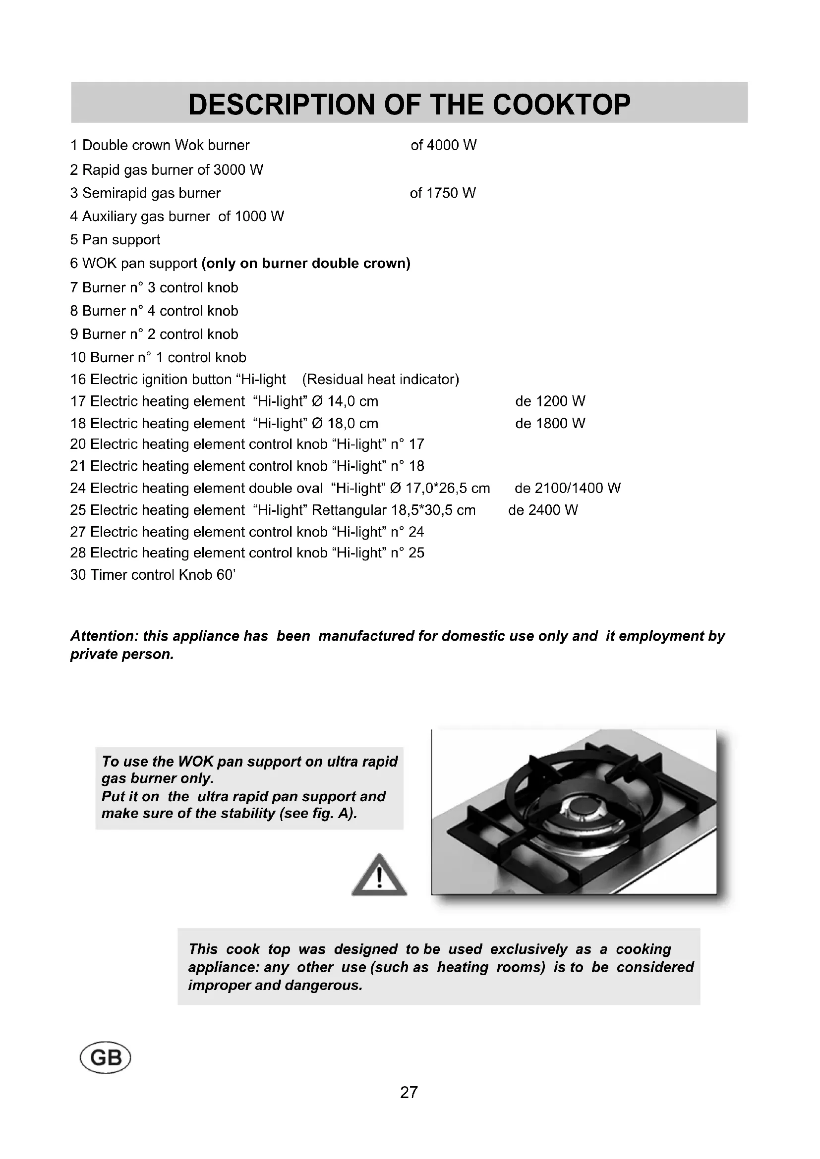
1 Double crown Wok burner of 4000 W 2 Rapid gas burner of 3000 W 3 Semirapid gas burner of 1750 W 4 Auxiliary gas burner of 1000 W 5 Pan support 6 WOK pan support (only on burner double crown) 7 Burner n° 3 control knob 8 Burner n° 4 control knob 9 Burner n° 2 control knob 10 Burner n° 1 control knob 16 Electric ignition button “Hi-light (Residual heat indicator) 17 Electric heating element “Hi-light” Ø 14,0 cm de 1200 W 18 Electric heating element “Hi-light” Ø 18,0 cm de 1800 W 20 Electric heating element control knob “Hi-light” n° 17 21 Electric heating element control knob “Hi-light” n° 18 24 Electric heating element double oval “Hi-light” Ø 17,0*26,5 cm de 2100/1400 W 25 Electric heating element “Hi-light” Rettangular 18,5*30,5 cm de 2400 W 27 Electric heating element control knob “Hi-light” n° 24 28 Electric heating element control knob “Hi-light” n° 25 30 Timer control Knob 60’ Attention: this appliance has been manufactured for domestic use only and it employment by private person.
DESCRIPTION OF THE COOKTOP
To use the WOK pan support on ultra rapid gas burner only. Put it on the ultra rapid pan support and make sure of the stability (see fig. A). Fig. A This cook top was designed to be used exclusively as a cooking appliance: any other use (such as heating rooms) is to be considered improper and dangerous.28 FIG. 2
A diagram is screen-printed above each knob on the front panel. This diagram indicates to which burner the knob in question corresponds. After having opened the gas mains or gas bottle tap, light the burners as described below: - Automatic electrical ignition Push and turn the knob corresponding to the required burner in an anticlockwise direction until it reaches the full on position (large flame fig.1), then depress the knob. - Lighting burners equipped with flame failure device The knobs of burners equipped with flame failure device must be turned in an anticlockwise direction until they reach the full on position (large flame fig. 1) and come to a stop. Now depress the knob in question and repeat the previously indicated operations. Keep the knob depressed for about 10 seconds once the burner has ignited. In the event of the Burner flames being accidentally extinguished, turn off the burner control and do not attempt to re-ignite the burner for a least 1 minute.
HOW TO USE THE BURNERS
Bear in mind the following indications in order to achieve maximum efficiency with the least possible gas consumption: - use adequate pans for each burner (consult the following table and fig. 2). - When the pan comes to the boil, set the knob to the reduced rate position (small flame fig. 1). - Always place a lid on the pans. - Use only pan with a flat bottom and in thick metal. WARNINGS: - burners with flame failure device may only be ignited when the relative knob has been set to the Full on position (large flame fig. 1). - Matches can be used to ignite the burners in a blackout. - Never leave the appliance unattended when the burners are being used. Make sure there are no children in the near vicinity. Particularly make sure that the pan handles are correctly positioned and keep a check on foods requiring oil and grease to cook since these products can easily catch fire. - Never use aerosols near the appliance when it is operating. - If the built-in hot plate has a lid, any spilt food should be immediately removed from this before it is opened. If the appliance has a glass lid, this could shatter when the hot plate becomes hot. Always switch off all the burners before closing the lid. - Utilize pots with flat bottom only. - Containers wider than the unit are not recommended. Burners Power ratings (W) Pan Ø in cm Double crown 4000 24 ÷ 26 Rapid 3000 20 ÷ 22 Semirapid 1750 16 ÷ 18 Auxiliary 1000 10 ÷ 14 Closed positionFull on positionReduced rateposition FIG. 129 (*) AIR INLET: SEE INSTALLATION CHAPTER (PARAGRAPHS 6 AND 7) USE WARNINGS AND ADVICE FOR THE USER: - use of a gas cooking appliance produces heat and moisture in the room in which it is installed. The room must therefore be well ventilated by keeping the natural air vents clear (fig. 3) and by activating the mechanical aeration device (suction hood or electric fan fig. 4 and fig. 5). - Intensive and lengthy use of the appliance may require additional ventilation. This can be achieved by opening a window or by increasing the power of the mechanical exhausting system if installed. - Do not attempt to change the technical characteristics of the product because it can be dangerous. - If you should not to use this appliance any more (or replace an old model), before disposing of it, make it inoperative in conformity with current law on the protection of health and the prevention of environmental pollution by making its dangerous parts harmless, especially for children who might play on an abandoned appliance. - Do not touch the appliance with wet or damp hands or feet. - Do not use the appliance barefoot. - The manufacturer will not be liable for any damage resulting from improper, incorrect or unreasonable use. - During, and immediately after operation, some parts of the cook top are very hot: avoid touching them. - After using the cook top, make sure that the knob is in the closed position and close the main tap of the gas supply or gas cylinder. - If the gas taps are not operating correctly, call the Customer Care Department. - The appliance must not be operated with an external timer or a separate remote-control system.
during operation the work surfaces of the cooking area become very hot: keep children away! FIG. 3 FIG. 4 FIG. 5 Never cook food directly on the electric plates but always in a pot or container.30 USE
2) SWITCHING ON THE ELECTRIC
PLATES “Hi-Ligts” Heating elements are controlled by energy regulators with 12 positions (see fig. A-B) that permit to obtain a big range of different temperatures. In Scheme, by way of information, we give instructions to obtain different cooking levels. To connect the heating elements is necessary to turn clockwise or anticlockwise the relative knob. Indicator light 16 shows the connection of one or more heating elements. The indicator will turn off only when the temperature of the cooking zone will be below the value: this is the reason why we call it residual heat indicator.
ACTIVATION OF THE DOUBLE ZONE
To activate the double zone simply rotate the knobs clock wise all the way through to position 0, as shown in Pic. A. In that position it is possible to regulate the temperature, while keeping the Double Zone switched on. To activate only one single heating element, simply rotate again the knob until position 0 is reached and switch on again, resetting the required heating levels. How to use the cooking zones Heating takes place only in the inside part of the circles drawn on the special glass. The circles have to be wholly covered by the pots. Zone n° 17 Ø 14,0 “Hi-light” 1200 W Zone n° 18 Ø 18,0 “Hi-light” 1800 W Zone n° 24 Ø 17,0*26,5 “Hi-light” 1400 - 2100 W Zone n° 25 18,5*30,5 “Hi-light” Rett. 2400 W Adjustment positions knobs control Possible cooking processes
To dissolve butter, chocolate, etc.. To heat small amounts of liquid.
To heat larger amounts of liquid. To prepare cremes and suces requiring long slow cooking times.
To thaw frozen foods and prepare stews, heat to boiling point or simmer.
To heat foods to boiling point. To brown delicate meats and fish. 8 -10 For escalopes and steaks. To simmer large amounts of food.
To bring large amounts of liquid to the boil. For frying. Position off Fig. A Position off Fig. B FIG. 1/A31 WARNINGS: for a correct use, please look at fig. 5/A and remind: -switch on the electricity only after having placed the pot on the cooking zone. -Use pots and pans with flat solid bottoms. -Use pots with the same diameter of the cooking zones. - Dry the bottom of the pot before put in on the cooking zones. - Do not scrape the pot against the glass so to not damage it. - During the use of the cooking zones, please, keep the children away from the hot plates. Make sure that the handles of the pots are placed in the right way towards the interior. Be aware that overheated fats and oils may become inflamed. - Cooking zones after using remain warm; don’t leave objects, don’t lean your hands so to avoid burns, till the indicator light is off. - If the glass cracks, please, disconnect the appliance. - Don’t use plastic pots or alluminium sheets. - Don’t use hob as a supplementary surface. - The appliance must not be operated with an external timer or a separate remote-control system. - Do not attempt to change the technical characteristics of the product because it can be dangerous. - If you should not to use this appliance any more (or replace an old model), before disposing of it, make it inoperative in conformity with current law on the protection of health and the prevention of environmental pollution by making its dangerous parts harmless, especially for children who might play on an abandoned appliance. WARNINGS AND ADVICE FOR THE USER: - do not touch the appliance with wet or damp hands or feet. - Do not use the appliance barefoot. - The manufacturer will not be liable for any damage resulting from improper, incorrect or unreasonable use. - During, and immediately after operation, some parts of the cook top are very hot: avoid touching them. - After using the cook top, make sure that the knob is in the closed position. - cook with a cover whenever possible to save electricity; - an indicator light near the knob shows when the electric plates are turned on. USE FIG. 5/A In order to cook with the heating element efficiently using the least amount of energy, use: thick, flat-bottomed pots of a width suited to that of the heating element (see picture). Cook with the lid on to also save energy. Turn down the heating element when it reaches boiling point. TIMER Timer allows to heating elements to turn off automatically by acoustic warning. It can be used also as timer (without turning off) and can be set for a period of max. 60 minutes (see fig. 1/A).32 CLEANING IMPORTANT: always disconnect the appliance from the gas and electricity mains before carrying out any cleaning operation.
Periodically wash the cooktop, pan support, the enamelled burner caps “A”, “B” and “C” and the burner heads "T" (see fig. 6/A - 6/B) with lukewarm soapy water. They should also be cleaned plugs "AC" and flame detection "TC" (see fig. 6/A). Clean them gently with a small nylon brush as shown (see fig. 6) and allow to dry fully. Do not wash in the dishwasher. Following this, all parts should be thoroughly rinsed and dried. Never wash them while they are still warm and never use abrasive powders. Do not allow vinegar, coffee, milk, salted water, lemon or tomato juice from remaining in contact with the enamelled surfaces for long periods of time. WARNINGS: comply with the following instructions, before remounting the parts: ●check that burner head slots “T” (fig. 6/A) have not become clogged by foreign bodies. ●Check that enamelled burner cap “A”, “B” and “C” (fig. 6/A - 6/B) have correctly positioned on the burner head. It must be steady. ●The exact position of the pan support is established by the rounded corners, which should be set towards the side edge of the cooktop. ●Do not force the taps if they are difficult open or close. Contact the technical assistance service for repairs. ●To keep in good condition the electric irons should be treated with appropriate cleaning products and prevent rust. ●Don’t use steam jets for the equipment cleaning. Note: continuous use could cause the burners to change colour due to the high temperature. FIG. 6 FIG. 6/A FIG. 6/B33 CLEANING Before any cleaning operation, disconnect the appliance from the electric circuit. ELECTRIC ELEMENT Hi-Light” If you want to preserve the surface clean and bright, we recommend you to use a silicone conditioner. The use of this conditioners, prior to jam-making, helps to protect the surface of the hob. It is very important to clean the surface soon after every use, when the glass is still tepid. Do not use metallic sponges, powder abrasives or corrosive sprays. Depending on the dirty level we recommend: - slights stains: it is enought the use of a moist clean rag. - Marks of liquid, overflowed from the pot, can be removed using vinegar or lemon. - Pay attention to not let fall sugar or element with sugar. In this case turn the switch off and clean the surface with hot water and a sponge. - After a period of time may appear metal reflex and scratches (fig. A) due to the wrong cleaning and the wrong use of the pots. The scratches are difficultly removable, but they do not compromise the good working of the hob. - Don’t use steam jets for the equipment cleaning. FIG. A CAUTION: In case of hotplate glass breakage: ●shut immediately off all burners and any electrical heating element and isolate the appliance from the power supply; ●do not touch the appliance surface; ●do not use the appliance.34 INSTALLATION TECHNICAL INFORMATION
Installation, adjustments of controls and maintenance must only be carried out by a qualified engineer. The appliance must be correctly installed in conformity with current law and the manufacturer's instructions. Incorrect installation may cause damage to persons, animals or property for which the Manufacturer shall not be considered responsible. During the life of the system, the automatic safety or regulating devices on the appliance may only be modified by the manufacturer or by his duly authorized dealer.
4) INSTALLING THE HOT PLATE
Check that the appliance is in a good condition after having removed the outer packaging and internal wrappings from around the various loose parts. In case of doubt, do not use the appliance and contact qualified personnel. Never leave the packaging materials (cardboard, bags, polystyrene foam, nails, etc.) within children’s reach since they could become potential sources of danger. The measurements of the opening made in the top of the modular cabinet and into which the cooktop will be installed are indicated in either fig. 7-7/A. Always comply with the measurements given for the hole into which the appliance will be recessed (see fig.7-/7A and minimun distance for fig. 8)
The prospective walls (left or right) that exceed the working table in height must be at a minimum distance from the cutting as mentionned both in the columns “E” of the scheme. The appliance belongs to class 3 and is therefore subject to all the provisions established by the provisions governing such appliances. COMPLY WITH THE DIMENSIONS (mm) IMPORTANT: a perfect installation, adjustment or transformation of the cook top to use other gases requires a QUALIFIED INSTALLER: a failure to follow this rule will void the warranty. FIG. 7/A FIG. 8 A B C D E F (30) 30.1 1H-2H 282 482 59 59 100 min 120 min. (30) 1-2 Gas 282 482 59 59 300 min 70 min. (60) 553 473 63.5 63.5 173.5 min. 70 min. (75) 553 473 63.5 63.5 173.5 min. 70 min. (90) 833 475 62.5 62.5 300 min. 70 min.35
5) FIXING THE HOT PLATE
The cooktop has a special seal which prevents liquid from infiltrating into the cabinet. Strictly comply with the following instructions in order to correctly apply this seal: - take off all the movable parts of the hob. - Detach the seals from their backing, checking that the transparent protection still adheres to the seal itself. - Overturn the cooktop and correctly position seal “E” (fig. 9) under the edge of the cooktop itself, so that the outer side of the seal perfectly matches the outer perimetral edge of the cooktop. The ends of the strips must fit together without overlapping. - Evenly and securely fix the seal to the cooktop, pressing into place with the fingers and remove the strip of protective paper from the seal and set the plate into the hole made in the cabinet. - Fix the hob with the proper brackets “S” and fit the prominent part into the porthole “H” on the bottom; turn the screw “F” until the bracket “S” stick on the top (fig. 10). - In order to avoid accidental touch with the overheating bottom of the hob, during the working, is necessary to put a wooden insert, fixed by screws, at a minimum distance of 70 mm from the top (see fig. 7-7/A). INSTALLATION FIG. 9 FIG. 10 FIG. 7 For fully electric model36 INSTALLATION IMPORTANT INSTALLATION INSTRUCTIONS The installer should note that the appliance that side walls should be no higher than the hot plate itself. Furthermore, the rear wall, the surfaces surrounding and adjacent to the appliance must be able to withstand a temperature of 90 °C. The adhesive used to stick the plastic laminate to the cabinet must be able to withstand a temperature of not less than 150 °C otherwise the laminate could come unstuck. The appliance must be installed in compliance with BS 6172 1990, BS 5440 part. 2 1989 and BS 6891 1988. This appliance is not connected to a device able to dispose of the combustion fumes. It must therefore be connected in compliance with the above mentioned installation standards. Particular care should be paid to the following provisions governing ventilation and aeration.
To ensure correct operation of the appliance, it is important to ensure that the room where the hot plate is installed has sufficient ventilation, as set out in BS 5440 part 2. 1989. See table below. Natural air flow must enter directly through permanent openings in the walls of the room in question. These must open towards the outside and possess a minimum section of 100 cm
see fig. 3). It must be impossible to obstruct these openings. Indirect ventilation with air drawn from adjacent rooms is permitted in strict compliance with the provisions in force. CAUTION: if the burners of the cooking top are without safety thermocouple, the ventilation outlet must have a minimum 200 cm² section.
7) LOCATION AND AERATION
Gas cooking appliances must always dispose of their combustion fumes through hoods. These must be connected to flues, chimneys or straight outside (see fig. 4). If it is not possible to install a hood, an electric fan can be installed on a window or on a wall facing outside (see fig. 5). This must be activated at the same time as the appliance, so long as the specifications in the provisions in force are strictly complied with.
Before connecting the appliance, check that the values on the data label affixed to the underside of the hot plate correspond to those of the gas mains in the home. A label on page 42 of this manual and on the product label indicates the type of gas and pressure adjustment.
a gas hot plate can only be connected by a CORGI Registered engineer. Installations should be carried out in accordance with BS 6891 1988 and must comply with the Gas Safety Regulations. All hot plate installations must include an isolation tap.
Some hot plates models have a test point fitted under the control panel, to conduct a gas pressure test proceed as follows: - turn off the gas supply. - Remove screw in the pressure test point, place test gauge connecting tube on test point. - Fit a burner ring and cap onto burner assembly, replace control knob onto corresponding control tap for the burner. - Turn on gas and ascertain working pressure. After test, turn off control tap, turn off gas supply, disconnect test gauge connecting tube. Replace the test point screw, turn gas back on and test for soundness. Reassemble the hotplate. IMPORTANT: The appliance complies with the provisions of the sub-regulations for European Directives: - 2009/142/EC (until April 20, 2018); - Regulation (EU) 2016/426 (from April 21, 2018).37 INSTALLATION
9) ELECTRICAL CONNECTION
The electrical connections of the appliance must be carried out in compliance with the provisions and standards in force. Before connecting the appliance, check that: - the voltage matches the value shown on the specification plate and the section of the wires of the electrical system can support the load, which is also indicated on the specification plate. - The electrical capacity of the mains supply and current sockets suit the maximum power rating of the appliance (consult the data label applied to the underside of the cooktop). - The socket or system has an efficient earth connection in compliance with the provisions and standards in force. The manufacturer declines all responsibility for failing to comply with these provisions. When the appliance is connected to the electricity main by a socket: - apply to the input cable “C”, if unprovided (see fig. 11) a normalized plug adequate to the load indicated in the identification label. Connect the cables according to the scheme of fig.11, making sure to respect the undermentioned respondences: Letter L (live) = brown wire; Letter N (neutral) = blue wire; Earth symbol = green - yellow wire. - The power supply cable must be positioned so that no part of it is able to reach an temperature of 90 °C. - Never use reductions, adapters of shunts for connection since these could create false contacts and lead to dangerous overheating. - The outlet must be accessible after the built-in. When the appliance is connected straight to the electricity main: - install an omnipolar circuit-breaker between the appliance and the electricity main. This circuit- breaker should be sized according to the load rating of the appliance and possess a minimum 3 mm gap between its contacts. - Remember that the earth wire must not be interrupted by the circuit-breaker. - The electrical connection may also be protected by a high sensitivity differential circuit- breaker. You are strongly advised to fix the relative yellow- green earth wire to an efficient earthing system. Before performing any service on the electrical part of the appliance, it must absolutely be disconnected from the electrical network. WARNINGS: all our products are conform with the European Norms and relative amendments. The product is therefore conform with the requirements of the European Directivesin force relating to: - compatibility electromagnetic (EMC); - electrical security (LVD); - restriction of use of certain hazardous substances (RoHS); - EcoDesign (ERP). IMPORTANT: the appliance must be installed following the manufacturer's instructions. The manufacturer will not be liable for injury to persons or animals or property damage caused by an incorrect installation. If the installation requires modifications to the home's electrical system or if the socket is incompatible with the appliance's plug, have changes or replacements performed by professionally-qualified person. In particular, this person must also make sure that the section of the wires of the socket is suitable for the power absorbed by the appliance. FIG. 1138 ADJUSTMENTS Always disconnect the appliance from the electricity main before making any adjustments. All seals must be replaced by the technician at the end of any adjustments or regulations. Our burners do not require primary air adjustment.
“Reduced rate” adjustment - Switch on the burner and turn the relative knob to the “Reduced rate” position (small flame fig. 1). - Remove knob “M” (fig. 12 and 12/A) of the tap, which is simply pressed on to its rod. The by-pass for minimal rate regulation can be: beside the tap (fig. 12) or inside the shaft. In any case, to access to regulation, it can be done trought the insertion of a small screwdriver ‘’D’’ beside the tap (fig. 12) or in the hole ‘’C’’ inside the shaft of the tap (fig 12/A). Turn the throttle screw to the right or left until the burner flame has been adequately regulated to the “Reduced rate” position. The flame should not be too low: the lowest small flame should be continuous and steady. Re- assemble the several components. It is understood that only burners operating with G20 gas should be subjected to the above mentioned adjustments. The screw must be fully locked when the burners operate with G30 or G31 gas (turn clockwise).
The burners can be adapted to different types of gas by installing injectors suited to the type of gas required. To do this, first remove the burner tops using a wrench “B”. Now unscrew injector “A” (see fig. 13) and fit a injector corresponding to the type of gas required. It is advisable to tighten the injector in place. After the injectors have been replaced, the burners must be regulated as explained in paragraphs 10. The technician must reset any seals on the regulating or pre-regulating devices and affix the label corresponding to the new gas regulation on the appliance instead of the already existing one. This label is supplied in the packet containing the spare injectors. The envelope with the injectors and the labels can be included in the kit, or at disposal to the authorized Customer Care Department. For the sake of convenience, the nominal rate chart also lists the heat inputs of the burners, the diameter of the injectors and the working pressures of the various types of gas. CONVERSIONS TABLE FIG. 13 *In accordance with Regulation No. 66/2014 EU measures for the implementation of Directive2009/125/EC, the performance (EEgas burner) was calculated according to EN 30-2-1 last review with the G20.40 CONVERSIONS
CABLE TYPES AND SECTIONS
ATTENTION!!! If the power supply cable is replaced, the installer should leave the ground wire longer (B) than the phase conductors (fig. 14) and comply with the recommendations given in paragraph 9. TYPE OF HOT PLATE TYPE OF CABLE
Hot plate with 1-2 “Hi-Light” element.
FIG. 14 DENOMINATIONS Ø (cm) POWER (W) ECelectric cooking* (Wh/Kg) Electric heating element “Hi-light” 14,0 1200 187,0 Electric heating element “Hi-light” 18,0
EFX 30 1H-T Tension 220 - 240 V ~ Frequency 50/60 Hz Tot. Rating 2400 W In case of failure or cut in the cable, please move away from the cable and do not touch it. Moreover the device must be unplugged and not switched on. Call the nearest authorized service center to fix the problem
In case of adaptation of the hob to another type of gas, operate as described in the directions for the and installation use and replace the label on the bottom with the one provided in the spare bag.45 This appliance is marked according to the European directive 2002/96/EC on Waste Electrical and Electronic Equipment (WEEE). This guideline is the frame of a European-wide validity of return and recycling on Waste Electrical and Electronic Equipment.
TECHNICAL ASSISTANCE AND SPARE PARTS
Before leaving the factory, this appliance will have been tested and regulated by expert and specialized personnel in order to guarantee the best performances. Any repairs or adjustments which may be subsequently required may only be carried out by qualified personnel with the utmost care and attention. For this reason, always contact your Dealer or our nearest After Sales Service Center whenever repairs or adjustments are required, specifying the type of fault and the model of the appliance in your possession. Please also note that genuine spare parts are only available from our After Sales Service Centers and authorized retail outlets. The above data are printed on the data label put on the inferior part of the appliance and on the packing label. The above informations give to the technical assistant the possibility to get fit spare parts and a heaven-sent intervention. We suggest to fill the table below. MARK: ............................................................................. MODEL: ........................................................................... SERIES: ........................................................................... Keep the Warranty Certificate or the sheet of technical data with the Instructions Handbook during the appliance life. It contains important technical data.46
EFX 60.1 4G AI AL CI
EFX 60.1 4G AI AL DR
EFX 30.1 1H EFX 30.1 1H-T
FREQUENCE = 50-60 Hz 4 FEUXS (60) (WOK sx)
FREQUENCE = 50-60 Hz 5 FEUXS (90) (WOK central)
FREQUENCE = 50-60 Hz 5 FEUXS (90) ( WOK sx )
FREQUENCE = 50-60 Hz 6 FEUXS (90) (WOK sx)
4 FEUXS (90) (1 elem. Oval Hi-light) WOK sx
5 FEUXS (75) (WOK central)
FREQUENCE = 50-60 Hz 2 FEUXS + 2 “Hi-light”
EFX 60.1 4G AI AL CI
EFX 60.1 4G AI AL DR
EFX 30.1 1H EFX 30.1 1H-T
EFX 60.1 4G AI AL CI
EFX 60.1 4G AI AL DR
EFX 30.1 1H EFX 30.1 1H-T
(Wh/Kg) Placa electric “Hi-light” 14,0 1200 187,0 Placa electric “Hi-light” 18,0