
KFGC500JSS - Cooker KITCHENAID - Free user manual and instructions
Find the device manual for free KFGC500JSS KITCHENAID in PDF.

| Product type | Gas range |
| Brand | KitchenAid |
| Model | KFGC500JSS |
| Dimensions (W x D x H) | 75.7 x 70.5 x 91.4 cm (30 in x 27 3/4 in x 36 in) |
| Width | 75.7 cm (29 7/8 in) |
| Depth with control panel | 70.5 cm (27 3/4 in) |
| Height (with rollers) | 91.4 cm (36 in) |
| Estimated weight | Approximately 90 kg (200 lb) |
| Electrical supply | 120 V, 60 Hz, 15 A, dedicated circuit |
| Gas supply | Natural gas (convertible to propane with conversion kit) |
| Gas type | Natural gas or propane (convertible) |
| Number of surface burners | 5 burners (depending on model) |
| Main burner (large) | 20,000 BTU (natural gas) / 13,000 BTU (propane) |
| Medium burner | 15,000 BTU (natural gas) / 12,000 BTU (propane) |
| Small burner | 5,000 BTU (natural gas) / 4,000 BTU (propane) |
| Oven | Gas oven with bake burner and broil |
| Oven bake burner | 18,900 BTU (natural gas) / 12,500 BTU (propane) |
| Broil burner | 14,800 BTU (natural gas) / 9,000 BTU (propane) |
| Ignition system | Electronic ignition (spark) |
| Safety device | Anti-tip bracket to be installed |
| Cleaning | Manual cleaning of burners, grates, and drip tray |
| Spare parts | Injectors, burner caps, grates, anti-tip bracket |
| Repairability | Easy gas conversion with provided kit |
| Warranty | Refer to user manual |
Frequently Asked Questions - KFGC500JSS KITCHENAID
User questions about KFGC500JSS KITCHENAID
0 question about this device. Answer the ones you know or ask your own.
Ask a new question about this device
Download the instructions for your Cooker in PDF format for free! Find your manual KFGC500JSS - KITCHENAID and take your electronic device back in hand. On this page are published all the documents necessary for the use of your device. KFGC500JSS by KITCHENAID.
USER MANUAL KFGC500JSS KITCHENAID
30^ (76.2 cm), 36^ (91.4 cm), AND 48^ (121.9 cm)
For residential use only
INSTRUCTIONS D'INSTALLATION
CUISINIÈRE À GAZ DE STYLE COMMERCIAL DE
30 PO (76,2 CM), 36 PO (91,4 CM) ET 48 PO (121,9 CM)
Location Requirements. 5
Electrical Requirements 7
Gas Supply Requirements. 7
INSTALLATION INSTRUCTIONS.9
Unpack the Range 9
Remove Door. 9
Install Anti-Tip Bracket. 10
Make Gas Connection 11
Verify Anti-Tip Bracket Location. 12
Install Griddle Tray. 12
Electronic Ignition System 12
Level Range. 13
Install Kick Plate. 13
Complete Installation 13
GAS CONVERSIONS. 14
Propane Gas Conversion. 14
Natural Gas Conversion. 22
SECURITE DE LA CUISINIÈRE 30
EXIGENCES D'INSTALLATION 32
Terminer I'installation. 42
CONVERSIONS POUR CHANGEMENT DE GAZ. 43
Installer: Leave installation instructions with the homeowner.
Homeowner: Keep installation instructions for future reference.
IMPORTANT :
Your safety and the safety of others are very important.
We have provided many important safety messages in this manual and on your appliance. Always read and obey all safety messages.

This is the safety alert symbol.
This symbol alerts you to potential hazards that can kill or hurt you and others.
All safety messages will follow the safety alert symbol and either the word "DANGER" or "WARNING."
These words mean:
DANGER
You can be killed or seriously injured if you don't immediately follow instructions.
WARNING
You can be killed or seriously injured if you don't follow instructions.
All safety messages will tell you what the potential hazard is, tell you how to reduce the chance of injury, and tell you what can happen if the instructions are not followed.
WARNING: If the information in these instructions is not followed exactly, a fire or explosion may result causing property damage, personal injury or death.
- Do not store or use gasoline or other flammable vapors and liquids in the vicinity of this or any other appliance.
-WHAT TO DO IF YOU SMELL GAS:
- Do not try to light any appliance.
- Do not touch any electrical switch.
- Do not use any phone in your building.
- Immediately call your gas supplier from a neighbor's phone. Follow the gas supplier's instructions.
- If you cannot reach your gas supplier, call the fire department.
-Installation and service must be performed by a qualified installer, service agency or the gas supplier.
WARNING: Gas leaks cannot always be detected by smell.
Gas suppliers recommend that you use a gas detector approved by UL or CSA.
For more information, contact your gas supplier.
If a gas leak is detected, follow the "What to do if you smell gas" instructions.
WARNING:
Never Operate the Top Surface Cooking Section of this Appliance Unattended
- Failure to follow this warning statement could result in fire, explosion, or burn hazard that could cause property damage, personal injury, or death.
- If a fire should occur, keep away from the appliance and immediately call your fire department.
DO NOT ATTEMPT TO EXTINGUISH AN OIL/GREASE FIRE WITH WATER.
IMPORTANT: Do not install a ventilation system that blows air downward toward this gas cooking appliance. This type of ventilation system may cause ignition and combustion problems with this gas cooking appliance resulting in personal injury or unintended operation.
In the State of Massachusetts, the following installation instructions apply:
■ Installations and repairs must be performed by a qualified or licensed contractor, plumber, or gas fitter qualified or licensed by the State of Massachusetts.
Acceptable Shut-off Devices: Gas Cocks and Ball Valves installed for use shall be listed.
A flexible gas connector, when used, must not exceed 4 feet (121.9 cm).

WARNING
Tip Over Hazard
A child or adult can tip the range and be killed.
Install anti-tip bracket to floor or wall per installation instructions.
Slide range back so rear range foot is engaged in the slot of the anti-tip bracket.
Re-engage anti-tip bracket if range is moved.
Do not operate range without anti-tip bracket installed and engaged.
Failure to follow these instructions can result in death or serious burns to children and adults.
To verify the anti-tip bracket is installed and engaged:
- Slide range forward.
- Look for the anti-tip bracket securely attached to floor or wall.
- Slide range back so rear range foot is under anti-tip bracket.
- See installation instructions for details.
INSTALLATION REQUIREMENTS
Tools and Parts
Gather the required tools and parts before starting installation. Read and follow the instructions provided with any tools listed here.
Tools Needed
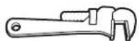
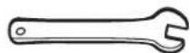
Pipe wrench Adjustable wrench or 5/8" (16 mm) wrench
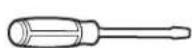
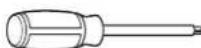
1/8" x 41/4" (3 mm x 100 mm) flat-blade screwdriver
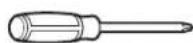
2 Phillips screwdriver
Drill 3 / 8'' (9.5 mm) drive ratchet 15/16" (24 mm)
combination wrench
Pliers
Level Tubing cutter 1 / 4'' (6.4 mm), 3 / 8'' (9.5 mm),
5/16" (7.9 mm) nut drivers
Marker or pencil

3/16" (4.8 mm) carbide tip masonry bit
Pipe-joint compound resistant to propane gas
Noncorrosive leak-detection solution
Tape measure
For Propane/Natural Gas Conversions
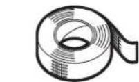
Large flat-blade screwdriver Adjustable wrench 7 mm Nut Driver Masking tape
1/2" (1.3 cm) open end wrench
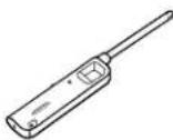
Lighter T20
© Torx Driver #1 Square Drive
2 Phillips Screwdriver
TORX and T20 are trademarks of Acument Intellectual Properties, LLC.
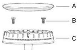
Parts Supplied
Check that all parts are included.
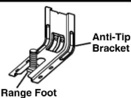
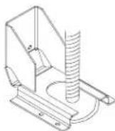
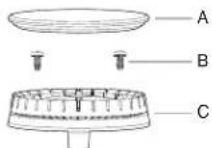
Anti-tip bracket kit
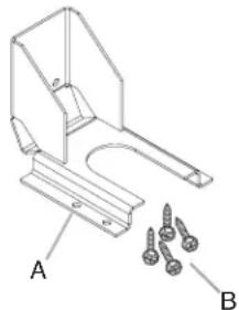
A. Anti-tip bracket
B. #8-18 x 1" (2.5 cm) Phillips head screws (4)
NOTE: Anti-tip bracket must be securely mounted to subfloor. Thickness of flooring may require longer screws to anchor bracket to subfloor. Longer screws are available from your local hardware store. See the "Install Anti-Tip Bracket" section.
■Burner grates
■Burner caps
Griddle drip tray (on griddle models)
Parts Needed
■All models must be installed with a guard if installing at zero clearance to a combustible back wall surface such as drywall. See "Cabinet Dimensions" in the "Location Requirements" section for installation requirements.
Check local codes and consult gas supplier. Check existing gas supply and electrical supply. See the "Electrical Requirements" and "Gas Supply Requirements" sections.
It is recommended that all electrical connections be made by a licensed, qualified electrical installer.
Location Requirements
IMPORTANT: Observe all governing codes and ordinances. Do not obstruct flow of combustion and ventilation air.
It is the installer's responsibility to comply with installation clearances specified on the model/serial/rating plate. The model/serial/rating plate is located under the console on the right-hand side.
It is recommended that a 585 CFM (993.9m^3 /hr) or larger range hood be installed above the range.
■Follow the range hood or microwave hood combination installation instructions for dimensional clearances above the cooktop surface.
■Recessed installations must provide complete enclosure of the sides and rear of the range.
All openings in the wall or floor where range is to be installed must be sealed.
■Do not seal the range to the side cabinets.
Cabinet opening dimensions that are shown must be used. Given dimensions are minimum clearances.
- The anti-tip bracket must be installed. To install the anti-tip bracket shipped with the range, see the "Install Anti-Tip Bracket" section.
Grounded electrical supply is required. See the "Electrical Requirements" section.
Proper gas supply connection must be available. See the "Gas Supply Requirements" section.
■Contact a qualified floor covering installer to check that the floor covering can withstand at least 200^ (93^) . Use an insulated pad or 1/4'' (6.4mm) plywood over carpet and under range if installing range over carpeting.
IMPORTANT: To avoid damage to your cabinets, check with your builder or cabinet supplier to make sure that the materials used will not discolor, delaminate, or sustain other damage. This oven has been designed in accordance with the requirements of UL and CSA International and complies with the maximum allowable wood cabinet temperatures of 194^ (90^) .
Mobile Home - Additional Installation Requirements
The installation of this range must conform to the Manufactured Home Construction and Safety Standard, Title 24 CFR, Part 3280 (formerly the Federal Standard for Mobile Home Construction and Safety, Title 24, HUD Part 280). When such standard is not applicable, use the Standard for Manufactured Home Installations, ANSI A225.1/NFPA 501A or local codes.
In Canada, the installation of this range must conform with the current standards CAN/CSA-A240-latest edition or with local codes.
Mobile Home Installations Require:
- When this range is installed in a mobile home, it must be secured to the floor during transit. Any method of securing the range is adequate as long as it conforms to the standards listed above.
The installation of appliances designed for recreational park trailers must conform with state or other codes or, in the absence of such codes, with the Standard for Recreational Park Trailers, ANSI A119.5.
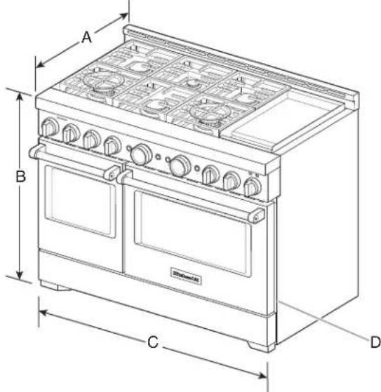
Product Dimensions
NOTE: Cooktop features may differ.
30^ (76.2cm) models
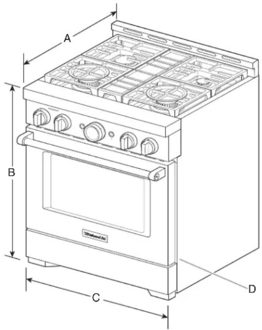
A. 27^3 / 4 (70.5 cm) depth with control panel (See NOTE).
B. 36'' (91.4 cm) range height when sitting on the wheels.
C. 29^7 / 8 " (75.7 cm) width
D. Model/serial/rating plate location/SAID label (located on front side panel).
36" (91.4 cm) models
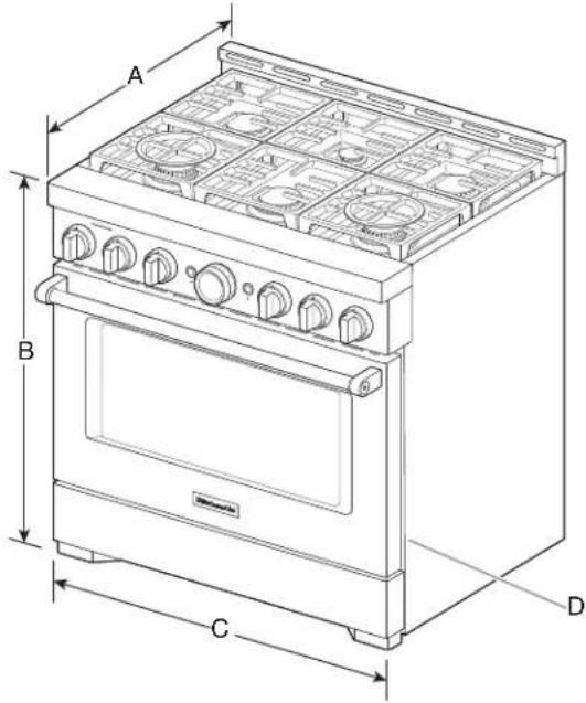
A. 27% (70.5 cm) depth with control panel (See NOTE).
B. 36^ (91.4 ~cm) range height when sitting on the wheels.
C. 35 18 (91.1 cm) width
D. Model/serial/rating plate location/SAID label (located on front side panel).
48" (121.9 cm) models
A. 27^3 / 4^n (70.5 cm) depth with control panel (See NOTE).
B. 36'' (91.4 cm) range height when sitting on the wheels.
C. 47 / 8^n (121.6 cm) width
D. Model/serial/rating plate location/SAID label (located on front side panel).
NOTE: When installed in a 24" (61.0 cm) base cabinet with 25" (63.5 cm) countertop; front of oven door protrudes 3" (7.6 cm) beyond 24" (61.0 cm) base cabinet.
Cabinet Requirements
Cabinet opening dimensions shown are for 25^ (64.0 cm) countertop depth, 24^ (61.0 cm) base cabinet depth, and 36^ (91.4 cm) countertop height. Dimensions must be met in order to ensure a flush fit to back wall.
IMPORTANT: If installing a range hood, hood liner, or microwave hood combination above the cooking surface, follow the range hood or microwave hood combination installation instructions for dimensional clearances above the cooking surface.
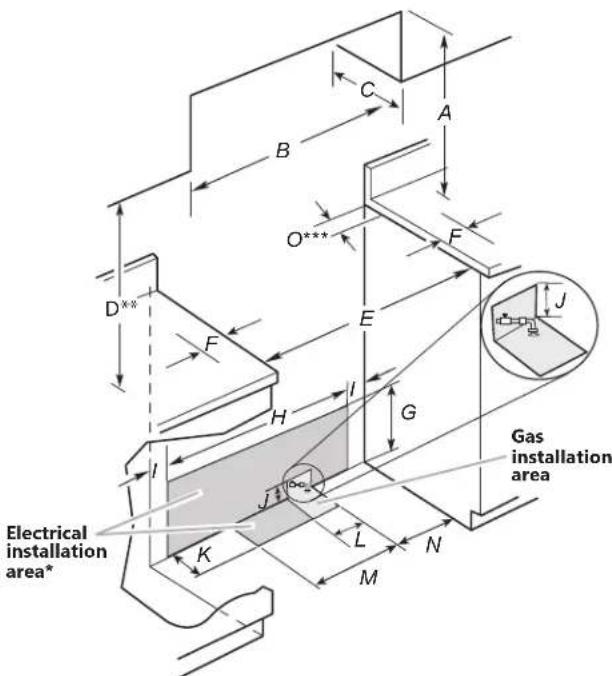
A. For minimum clearance to top of range.**
B. 30^ (76.2cm) model: 30^ (76.2cm) minimum upper cabinet width, 36^ (91.4cm) model: 36^ (91.4cm) minimum upper cabinet width, 48^ (121.9cm) model: 48^ (121.9cm) minimum upper cabinet width.
C. 13" (33 cm) maximum upper cabinet depth
D. 18^ (45.7 cm) upper cabinet to countertop
E. 30^ (76.2cm) on 30^ (76.2cm) models. 36^ (91.4cm) on 36^ (91.4cm) models. 48^ (121.9cm) on 48^ (121.9cm) models.
F. 12^th (30.4 cm) minimum clearance from both sides of range to side wall or other combustible material.
G. 15^ (38.1cm)
H. 22^ (55.9cm) on 30^ (76.2cm) models. 28"71.1 cm) on 36"91.4 cm) models. 40" (101.6 cm) on 48" (121.9 cm) models.
1. 4''(10.1cm)
J. 3^ (7.6cm)
K. 5^ (12.7cm)
L. 3'' (7.6 cm) on 30" (76.2 cm) models.
11" (27.9 cm) on 36" (91.4 cm) models.
21" (53.3 cm) on 48" (121.9 cm) models.
M. 7 / 2 (19.0 cm)
N. 9'' (22.9 cm)
O. 6'' (15.2 cm)***
** If not using ventilation, Minimum Clearances
30^ (76.2 cm) models: 42^ (106.7 cm) minimum clearance between the top of the cooking platform and the bottom of a combustible surface.
36'' (91.4 cm) models: 42'' (106.7 cm) minimum clearance between the top of the cooking platform and the bottom of a combustible surface.
48" (121.9 cm) models: 48" (121.9 cm) minimum clearance between the top of the cooking platform and the bottom of a combustible surface.
**If the surface of the back wall is constructed of a combustible material and a backguard is not installed, a 6" (15.2 cm) minimum clearance is required for all models.
Electrical Requirements
WARNING

Electrical Shock Hazard
Plug into a grounded 3 prong outlet.
Do not remove ground prong.
Do not use an adapter.
Do not use an extension cord.
Failure to follow these instructions can result in death, fire, or electrical shock.
IMPORTANT: The range must be electrically grounded in accordance with local codes and ordinances or, in the absence of local codes, with the National Electrical Code, ANSI/NFPA 70 or Canadian Electrical Code, CSA C22.1.
If codes permit and a separate ground wire is used, it is recommended that a qualified electrical installer determine that the ground path is adequate.
A copy of the above code standards can be obtained from:
National Fire Protection Association
Batterymarch Park
Quincy, MA 02169-7471
CSA International
8501 East Pleasant Valley Road
Cleveland, Ohio 44131-5575
A 120V 60Hz AC only, 15 A, fused electrical circuit is required. A time-delay fuse or circuit breaker is also recommended. It is recommended that a separate circuit serving only this range be provided.
Electronic ignition systems operate within wide voltage limits, but proper grounding and polarity are necessary. Check that the outlet provides 120V power and is correctly grounded.
The wiring diagram is located behind the kick plate in a clear plastic bag.
Gas Supply Requirements
WARNING
Explosion Hazard
Use a new CSA International approved gas supply line.
Install a shut-off valve.
Securely tighten all gas connections.
If connected to propane, have a qualified person make sure gas pressure does not exceed 14" (36 cm) water column.
Examples of a qualified person include:
licensed heating personnel, authorized gas company personnel, and authorized service personnel.
Failure to do so can result in death, explosion, or fire.
Observe all governing codes and ordinances.
IMPORTANT: This installation must conform with all local codes and ordinances. In the absence of local codes, installation must conform with American National Standard, National Fuel Gas Code ANSI Z223.1/NFPA 54 - latest edition - or in Canada, the Natural Gas and Propane Installation Code, CSA B149.1 - latest edition.
IMPORTANT: Range must be connected to a regulated gas supply.
IMPORTANT: Leak testing of the range must be conducted according to the manufacturer's instructions.
Type of Gas
Natural Gas:
This range is factory set for use with Natural gas. The model/serial/rating plate, located under the console on the right-hand side, has information on the types of gas that can be used. If the types of gas listed do not include the type of gas available, check with the local gas supplier.
Propane Gas conversion:
Conversion must be done by a qualified service technician.
No attempt shall be made to convert the range from the gas specified on the model/serial/rating plate for use with a different gas without consulting the serving gas supplier. To convert to Propane gas, use the Propane gas conversion kit provided with your range and see the "Gas Conversions" section. The parts for this kit are in the package containing literature supplied with the range.
Gas Supply Line
- Provide a gas supply line of 3/4'' (1.9 cm) rigid pipe to the range location. A smaller size pipe on longer runs may result in insufficient gas supply. With Propane gas, piping or tubing size can be 1/2'' (1.3 cm) minimum. Usually, Propane gas suppliers determine the size and materials used in the system.
NOTE: Pipe-joint compounds that resist the action of Propane gas must be used. Do not use TEFLOW*tape.
Flexible metal appliance connector:
If local codes permit, a new CSA design-certified, 4-5 ft (122-152 cm) long, 5/8'' (1.6 cm) or 3/4'' (1.9 cm) I.D., flexible metal appliance connector may be used for connecting the range to the gas supply line.
A 1 / 2'' (1.3 cm) male pipe thread is needed for connection to the female pipe threads of the inlet to the appliance pressure regulator.
- Do not kink or damage the flexible metal tubing when moving the range.
IMPORTANT: All connections must be wrench-tightened. Do not make connections to the gas regulator too tight. Making the connections too tight may crack the regulator and cause a gas leak. Do not allow the regulator to turn or move when tightening fittings.
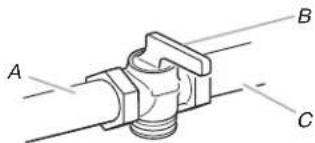
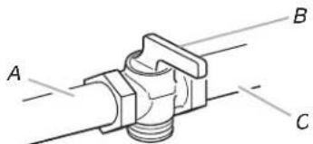
Must include a shut-off valve:
Install a manual gas line shut-off valve in an easily accessible location. Do not block access to shut-off valve. The valve is for turning on or shutting off gas to the range.
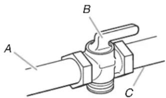
A. Gas supply line
B. Shut-off valve open position
C. To range
Gas Pressure Regulator
The gas pressure regulator supplied with this range must be used. The inlet pressure to the regulator should be as follows for proper operation:
Natural Gas:
Minimum pressure: 5^ (12.7 cm) WCP
Maximum pressure: 14^ (35.6 cm) WCP
Propane Gas:
Minimum pressure: 10^ (25.4 cm) WCP
Maximum pressure: 14^n (35.6 cm) WCP
Contact local gas supplier if you are not sure about the inlet pressure.
Burner Input Rating - Altitude
Input ratings shown on the model/serial/rating plate are for elevations up to 2,000 ft (609.6 m).
For elevations above 2,000 ft (609.6 m), ratings need to be reduced at a rate of 4% for each 1,000 ft (304.8m) above sea level (not applicable for Canada).
Gas Supply Pressure Testing
Gas supply pressure for testing regulator must be at least 1^ (2.5 cm) water column pressure above the manifold pressure shown on the model/serial/rating plate.
Line pressure testing above 1/2 psi (3.5 kPa) gauge (14" [35.6 cm] WCP)
The range and its individual shut-off valve must be disconnected from the gas supply piping system during any pressure testing of that system at test pressures in excess of 1/2 psi (3.5kPa) .
Line pressure testing at 1/2 psi (3.5 kPa) gauge (14" [35.6 cm] WCP) or lower
The range must be isolated from the gas supply piping system by closing its individual manual shut-off valve during any pressure testing of the gas supply piping system at test pressures equal to or less than 1/2 psi (3.5kPa) .
TEFLON is a registered trademark of Chemours.
Unpack the Range
WARNING
Excessive Weight Hazard
Use two or more people to move and install range.
Failure to do so can result in back or other injury.
Remove shipping materials, tape, and film from range.
Keep shipping pallet under range. Remove oven racks, and parts package from inside oven. Remove grates from top of oven.
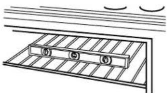
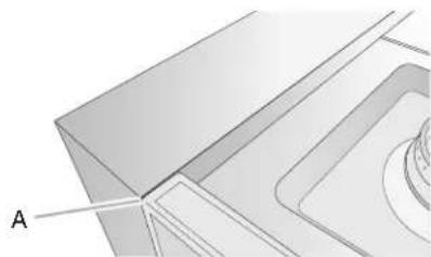
Remove Kick Plate
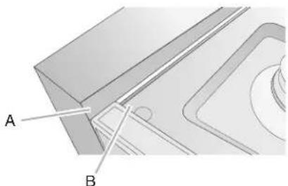
- Your range will have the kick plate packaged on top of the unit.
a. Remove kick plate from top of range and grate pack. In packaging
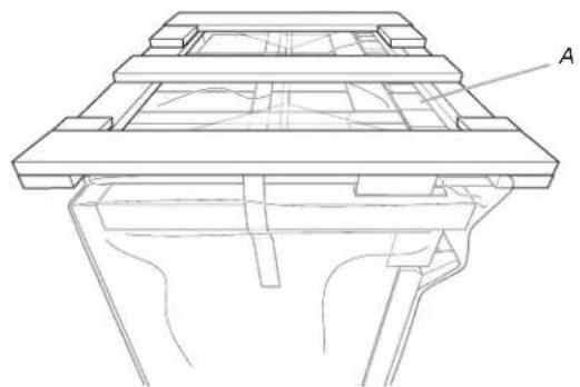
A. Kick plate
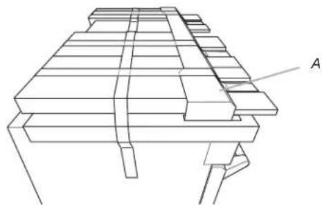
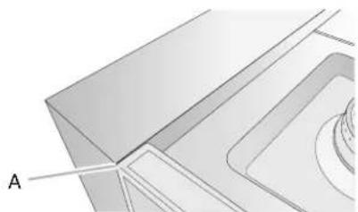
Packaging removed
A. Kick plate
b. Lay kick plate to the side to avoid scratching.
- For 48" (121.9 cm) models only, rotate center support counterclockwise off the pallet until it stops.
NOTE: This support is used only for shipping and is not needed for installation.
- Lay a piece of cardboard from packaging on the floor behind range. Using two or more people, firmly grasp each side of range. Lift range up about 3'' (8.0 cm) and move it back until range is off shipping pallet. Set range on cardboard to avoid damaging floor.
Remove Door
Door Removal
- Do not remove the side door spacers until the range is ready to install. Removing the door spacers could allow the door to shift, damaging the door latch.
■Do not lift or move the range by the door handle(s) or control panel.
Prior to installing the range, you will need to remove the oven door(s). Prepare a surface where you will place the door(s). This surface should be flat and covered with a soft blanket, or use the corner posts from the packaging material.
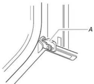
A. Oven door hinge in the locked position.
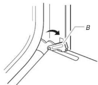
B. Oven door hinge in the unlocked position.
Partially close the door to engage the door latch locks. The door will stop at this point.
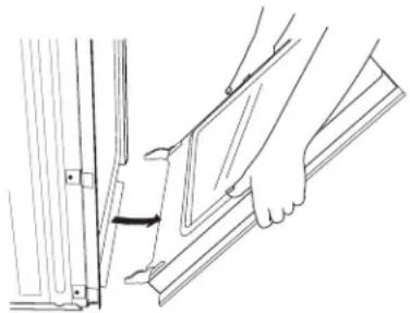
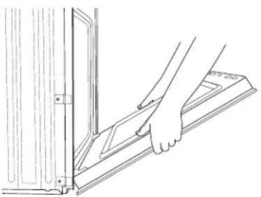
Use two hands to remove and replace the oven door(s). It may be necessary to gently shift door from side to side.
A. Slot in the oven frame for the door hinge lock.
Replace the Door
To replace the oven door(s), locate the slots in the oven cavity for the hinge locks and repeat the steps above in reverse order. Make sure the door closes properly and there is no interference from the door latch. If necessary, remove the door and repeat the steps above. If power is connected to the range, open and close the door to make sure the oven light comes on and goes off appropriately.
The range is equipped with leveling legs and rollers. Once the range is removed from the shipping pallet, make sure the leveling legs are not touching the floor and use the rollers to move the range into position. Always cover the flooring surface to avoid damage to the floor. Do not roll the range directly on the floor.
Install Anti-Tip Bracket
WARNING

Tip Over Hazard
A child or adult can tip the range and be killed.
Install anti-tip bracket to floor or wall per installation instructions.
Slide range back so rear range foot is engaged in the slot of the anti-tip bracket.
Re-engage anti-tip bracket if range is moved.
Do not operate range without anti-tip bracket installed and engaged.
Failure to follow these instructions can result in death or serious burns to children and adults.
- Determine which mounting method to use: floor or wall. If you have a stone or masonry floor, you can use the wall mounting method.
- Determine and mark centerline of the cutout space. The mounting bracket must be installed on the left side of the cutout. Position mounting bracket in cutout as shown in the following illustration.
Measurement B:
30^ (76.2cm) ranges: 13^ (33.0cm)
36^ (91.4 cm) ranges: 16^ (40.6 cm)
48" (121.9 cm) ranges: 22" (55.9 cm)
Measurement C:
Optional distance from back wall. If back wall is constructed of a combustible material and a backguard is not installed, a 6'' (15.2 cm) minimum clearance is required for all models. Install anti-tip bracket accordingly.
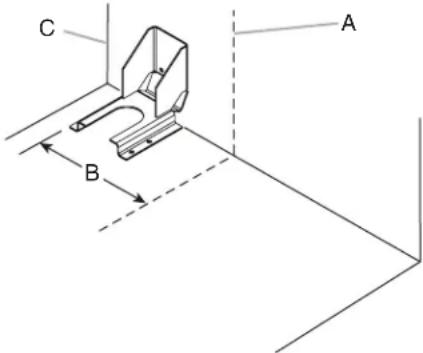
A. Centerline
B. Centerline of cutout to outside edge of anti-tip bracket.
C. Back wall to back of range
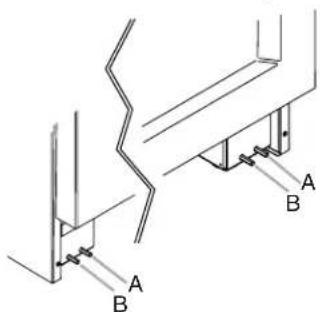
- Drill two 1/8'' (3.0 mm) holes that correspond to the bracket holes of the determined mounting method. See the following illustrations.
Floor Mounting
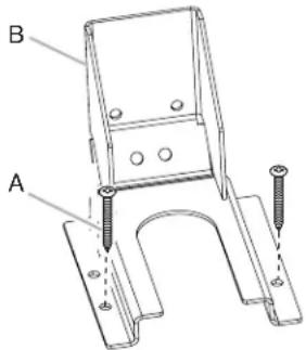
A. #12 x 15/8" (4.1 cm) screws
B. Anti-tip bracket
Wall Mounting
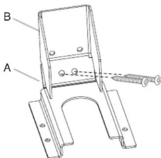
A. 12 × 1^5 / 8^n (4.1 cm) screws
B. Anti-tip bracket
- Using a Phillips screwdriver, mount anti-tip bracket to the wall or floor with the two # 12 × 1^5/8 (4.1 cm) screws provided.
Depending on the thickness of your flooring, longer screws may be necessary to anchor the bracket to the subfloor. Longer screws are available from your local hardware store. - Move range close enough to opening to allow for electrical connections to be made. Remove shipping base, cardboard, or hardboard from under range.
- Continue installing your range using the following installation instructions.
Make Gas Connection
WARNING
Explosion Hazard
Use a new CSA International approved gas supply line.
Install a shut-off valve.
Securely tighten all gas connections.
If connected to propane, have a qualified person make sure gas pressure does not exceed 14" (36 cm) water column.
Examples of a qualified person include:
licensed heating personnel, authorized gas company personnel, and authorized service personnel.
Failure to do so can result in death, explosion, or fire.
- Assemble flexible connector from gas supply pipe to pressure regulator located in the middle rear of the range.
- Apply pipe-joint compound made for use with Propane gas to the smaller thread ends of the flexible connector adapters. (See B and G in the following illustration.)
- Attach one adapter to the gas pressure regulator and the other adapter to the gas shut-off valve. Tighten both adapters, being certain not to move or turn the gas pressure regulator.
- Use a 15 / 16'' (2.4 cm) combination wrench and an adjustable wrench to attach the flexible gas supply to the adapters. Check that connector is not kinked.
IMPORTANT: All connections must be wrench-tightened. Do not make connections to the gas regulator too tight. Making the connections too tight may crack the regulator and cause a gas leak. Do not allow the regulator to turn or move when tightening fittings.
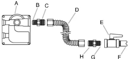
A. Gas pressure regulator
B. Use pipe-joint compound.
C. Adapter (must have 1 / 2 [1.3 cm] male pipe thread).
D. Flexible connector
E. Manual gas shut-off valve
F. 1 / 2^n(1.3cm) or
3/4" (1.9 cm) gas pipe.
G. Use pipe-joint compound.
H. Adapter
Complete Connection
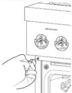
- Open the manual shut-off valve in the gas supply line. The valve is open when the handle is parallel to the gas pipe.
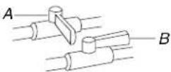
A. Closed valve
B. Open valve
- Test all connections by brushing on an approved noncorrosive leak-detection solution. If bubbles appear, a leak is indicated. Correct any leak found.
- Remove range burner caps, and grates from parts package. Place burner caps on burner bases. Place grates over burners and caps.
WARNING

Electrical Shock Hazard
Plug into a grounded 3 prong outlet.
Do not remove ground prong.
Do not use an adapter.
Do not use an extension cord.
Failure to follow these instructions can result in death, fire, or electrical shock.
- Plug into a grounded 3-prong outlet.
- Turn on power supply. For further information, please refer to the user instructions located in the Use and Care Guide.
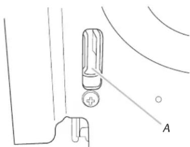
Verify Anti-Tip Bracket Location
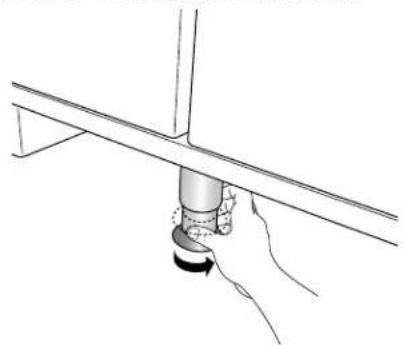
- Using a 5/16" (7.9 mm) socket or wrench, turn all four leveling rods one full turn to raise the range and provide enough clearance for the rear leveling leg to slide into the anti-tip bracket.
- Move range into its final location, making sure rear leveling leg slides into anti-tip bracket.
- Use a flashlight to look underneath the bottom of the range and visually check that the rear range foot is inserted into the slot of the anti-tip bracket.
Install Griddle Tray
(On griddle models)
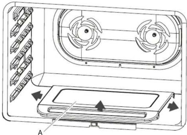
The griddle is factory installed.
- Place drip tray in the well at the front of the griddle. Slide tray toward the back until it stops.
A. Griddle drip tray
B. Griddle
- Clean griddle before using. Refer to the Use and Care Guide.
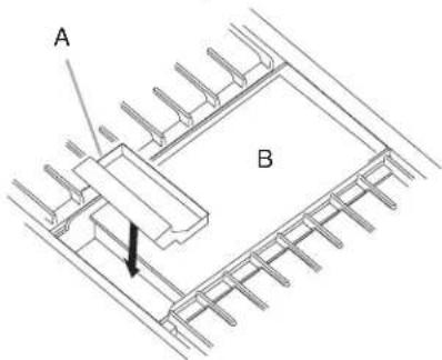
Electronic Ignition System
Install Burner Caps
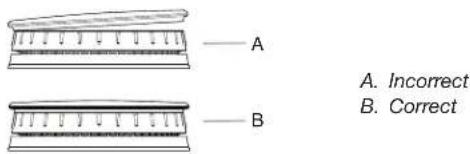
Place burner caps on top of burner. If burner caps are not properly positioned, surface burners will not light.
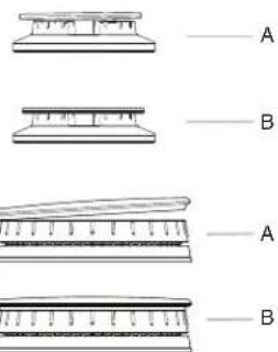
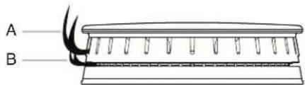
Burners
A. Incorrect
B. Correct
Initial Lighting and Gas Flame Adjustments
Range burners use electronic ignitors in place of standing pilots. When the Range Control Knob is turned to any position, the system creates a spark to light the burner. This sparking continues until the flame is lit or the knob is turned to OFF.
NOTE: The first time igniting the burners will take longer. This allows the gas to reach the burners during the first use.
Check Operation of Range Burners
Push in and turn each Control Knob to
NOTE: You will hear a clicking sound while the line clears.
The surface burners and grill flames should light within 4 seconds. The first time a burner is lit, it may take longer than 4 seconds to light because of air in the gas line.
After verifying the proper burner operation, turn the Control Knobs to OFF.
If burners do not light properly:
Turn Range Control Knob to OFF.
Check that the range is plugged in and the circuit breaker has not tripped or the fuse has not blown.
Check that the gas shut-off valves are set to the open position.
■Check that burner caps are properly positioned on burner bases.
Repeat startup. If a burner does not light at this point, contact your dealer or authorized service company for assistance.
Flame Height
The range flame should be a steady blue flame.
NOTE: Flame heights are factory set. If they don't appear correct, please contact your service provider.
Burner
A. Upper (main) flame
B. Lower (simmer) flame
NOTE: Dual Stacked burner shown.
Level Range
NOTE: Range must be level for satisfactory baking performance.
- Place rack in oven.
- Place level on rack and check levelness of the range, first side to side, then front to back.
- If range is not level, adjust the leveling rods. Using a wrench, turn leveling rods located behind the kick plate to level range and to raise or lower range to the desired countertop height.
NOTE: All roller feet must be off the floor upon final installation.
A. Rear leveling rod
B. Front leveling rod
NOTE: Turning clockwise raises the unit, whereas turning counterclockwise lowers the unit.
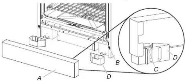
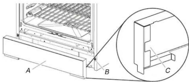
Install Kick Plate
NOTE: Door must be removed in order to remove or replace kick plate. Refer to the "Remove Door" section.
Align kick plate over the kick plate slots and push kick plate down.
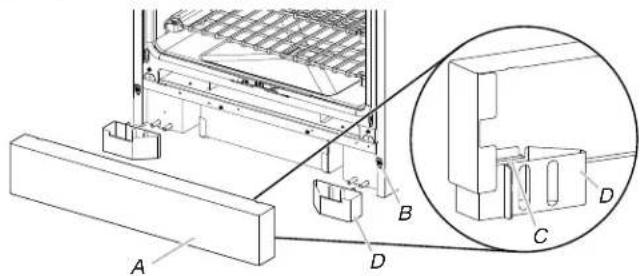
A. Kick plate
B. Kick plate tab
C. Kick plate slot
D. Feet
Complete Installation
- Check that all parts are now installed. If there is an extra part, go back through the steps to see which step was skipped.
- Check that you have all of your tools.
- Dispose of/recycle all packaging materials.
- For oven use and cleaning, read the Use and Care Guide.
Check Operation of Oven(s)
- Turn power on.
- Start a Bake cycle. See the Use and Care Guide for operating instructions.
If oven(s) does not operate, check the following:
Household fuse is intact and tight or circuit breaker has not tripped.
Electrical supply is connected.
See the "Troubleshooting" section in the Use and Care Guide.
- When oven has been on for 10-15 minutes, open the oven door and feel for heat.
If you do not feel heat, turn off the oven and contact a qualified technician.
If you need Assistance or Service:
Please reference the "Assistance or Service" section of the Use and Care Guide or contact the dealer from whom you purchased your range.
GAS CONVERSIONS
IMPORTANT: Gas conversions from Natural gas to Propane gas must be done by a qualified installer.
WARNING
Explosion Hazard
Use a new CSA International approved gas supply line. Install a shut-off valve.
Securely tighten all gas connections.
If connected to propane, have a qualified person make sure gas pressure does not exceed 14^ (36 cm) water column.
Examples of a qualified person include:
licensed heating personnel, authorized gas company personnel, and authorized service personnel.
Failure to do so can result in death, explosion, or fire.
Propane Gas Conversion
WARNING

Tip Over Hazard
A child or adult can tip the range and be killed.
Install anti-tip bracket to floor or wall per installation instructions.
Slide range back so rear range foot is engaged in the slot of the anti-tip bracket.
Re-engage anti-tip bracket if range is moved.
Do not operate range without anti-tip bracket installed and engaged.
Failure to follow these instructions can result in death or serious burns to children and adults.
- Turn the manual shut-off valve to the closed position.
A. To range
B.Shut-off valve (closed position)
C. Gas supply line
- Unplug range or disconnect power.
To Convert Gas Pressure Regulator from Natural Gas to Propane
NOTE: Door must be removed in order to remove or replace kick plate. Refer to the "Remove Door" section.
- Lift the kick plate up and off of the kick plate tab.
A. Kick plate
B. Kick plate tab
C. Kick plate slot
D. Feet
- Gently lay kick plate aside to avoid scratching.
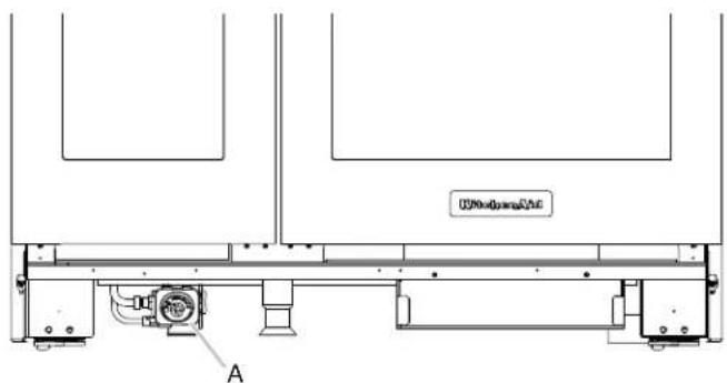
- Locate the gas pressure regulator at the left rear of the range.
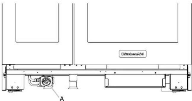
A. Gas pressure regulator
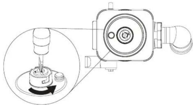
- Remove the gas pressure regulator cap by using a large flat-blade screwdriver, turning the regulator cap counterclockwise.
NOTE: Do not remove the spring beneath the cap.
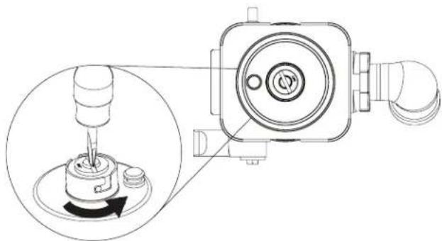
- Turn over the gas pressure regulator cap, and reinstall on the regulator so that the hollow end faces out and the letters "LP" are visible.
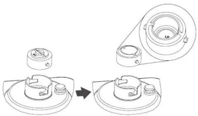
- Tighten the gas pressure regulator cap by using a large flat-blade screwdriver, turning the regulator cap clockwise.
- Test the gas pressure regulator and gas supply line. The regulator must be checked at a minimum 1^ (2.5 cm) water column above the set pressure. The inlet pressure to the regulator should be as follows for operation and checking the regulator setting:
Propane Gas:
Minimum pressure: 10^ (25.4 cm) WCP
Maximum pressure: 14^ (35.6 cm) WCP
Gas Supply Pressure Testing
Gas supply pressure for testing regulator must be at least 1^ (2.5 cm) water column pressure above the manifold pressure shown on the model/serial/rating plate.
Line pressure testing above 1/2 psi (3.5 kPa) gauge (14" [35.6 cm] WCP)
The range and its individual shut-off valve must be disconnected from the gas supply piping system during any pressure testing of that system at test pressures in excess of 1/2 psi (3.5kPa) .
Line pressure testing at 1/2 psi (3.5 kPa) gauge (14" [35.6 cm] WCP) or lower
The range must be isolated from the gas supply piping system by closing its individual manual shut-off valve during any pressure testing of the gas supply piping system at test pressures equal to or less than 1/2 psi (3.5 kPa).
To Convert Surface Burners from Natural Gas to Propane
- If the burner grates are installed, remove them.
- Remove burner cap.
- Remove the burner base by first removing (2) T-20 screws.
Burner
A. Burner cap
B. Screws
C. Burner base
-
Apply masking tape to the end of a 7mm nut driver to help hold the gas orifice spud in the nut driver while changing it. Insert nut driver into the gas opening and press down onto the gas orifice spud and remove by turning the gas orifice spud counterclockwise and lifting out. Set gas orifice spud aside.
-
Replace with correct Propane gas orifice spud. See the "Propane Gas Orifice Spud/Hood Chart". Use the following chart to find the exact orifice spud placement.
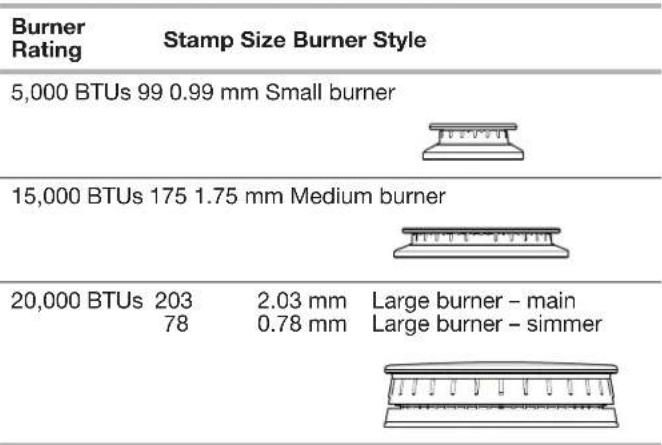
Propane Gas Orifice Spud/Hood Chart
| Burner Rating | Stamp Size Burner Style | |
| 4,000 BTUs 63 0.63 mm Small burner | ||
| 12,000 BTUs 103 1.03 mm Medium burner | ||
| 13,000 BTUs 99 | 0.99 mm | Large burner - main |
| 50 | 0.50 mm | Larger burner - simmer |
NOTE: Refer to serial tag for more information on burner ratings and locations.
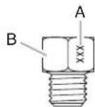
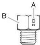
Burner orifice spud
A. Size stamp
B. Fuel type stamp (L or N)
- Place Natural gas orifice in plastic parts bag for future use and keep with package containing literature.
NOTE: There may be extra orifices in your kit.
- Replace the burner base and screws. Tighten screws only until burner is snug to cooktop, do not over-tighten.
- Replace burner cap.
- Repeat steps 2 through 8 for the remaining burners.
Adjusting Simmer Low Setting on Surface Burners for Propane
- Unplug range or disconnect power.
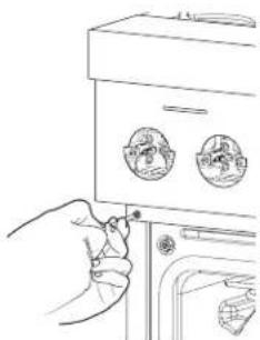
- Using the square bit screwdriver, remove the surface burner control knobs and bezels (Oven control knobs and griddle control knobs do not have to be removed).
- Open the oven door and remove the two screws on each side of the range that hold the control console in place.
NOTE: Make sure to leave the door open or the control console will not rest in the side brackets properly once it is attached.
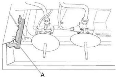
- Pull up on the control console and let it drop forward into the notched console brackets on each side.
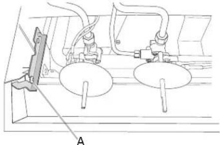
A. Control console bracket
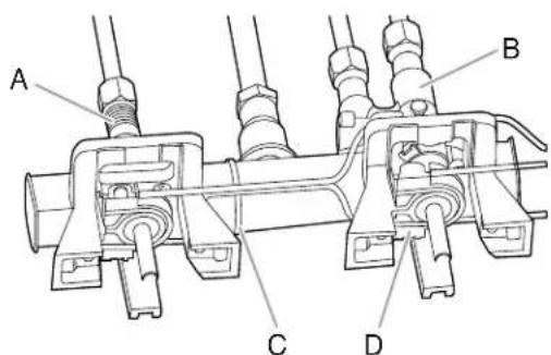
- Locate the appropriate low-turndown screw for the appropriate burner on the given valve. The low-turndown screw for the left rear, right rear, center rear, and center front burner valves (aluminum) is located through the center of the valve stem. The low-turndown screw for the left front and right front burner valves (brass) is located behind the ignition switch on the valve body, left of the stem. To remove the ignition switch cut the wire tie and pull the switch off the valve stem.
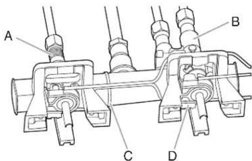
A. Aluminum Valve for Left Rear, Right Rear, Center Rear, and Center Front burners.
B. Brass Valve for Left Front and Right Front Dual burners.
C.Wire Tie
D. Ignition switch
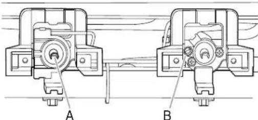
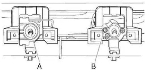
A. Low-turndown adjustment screw for Aluminum Valve through center of stem.
B. Low-turndown adjustment screw for Brass Valve.
- With the burner ON (the burner will have to be lit manually with a lighter), and set to simmer LOW, adjust the simmer flame down to the proper BTU level. Using a 1/8'' × 414'' (3.2 mm x 10.8 cm) flat blade screwdriver, turn the simmer low-turndown adjustment screw clockwise until the flame height is at, or below, the bottom of the cap. If the flame becomes unstable and flickers or appears to race around the burner, the adjustment is too low and the screw should be adjusted counterclockwise until the flame is stable. Repeat this step for all surface burners.
NOTE: Use a knob to adjust the burner valve.
NOTE: Adjust each burner individually.
- After adjustments are completed, replace the ignition switches onto the valves.
- Lift up on the control console and set it back into place. For a proper fit, the flange of the control console must hook over the lip on the front of the range cooktop.
NOTE: It may be necessary to lift valve stems to align with console holes.
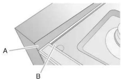
A. Control console flange
B. Front lip of range cooktop
- Check that the control console is flush with the top edge of the range.
A. Flush with range top
- Replace the screws on each side of the control console.
- Replace the bezels using the two screws which attach to the valve brackets, making note that there are front and rear bezels and will only attach properly in the correct location on the console.
- Push the Surface Knobs onto the valve stems.
- Replace the burner grates.
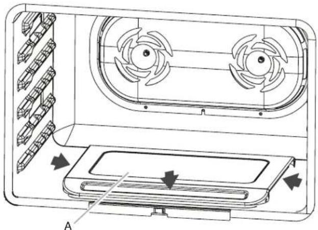
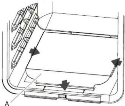
Convert Oven Bake Burner (30^ [76.2cm] and 36^ [91.4cm] models and the right oven cavity on 48^ [121.9cm] models)
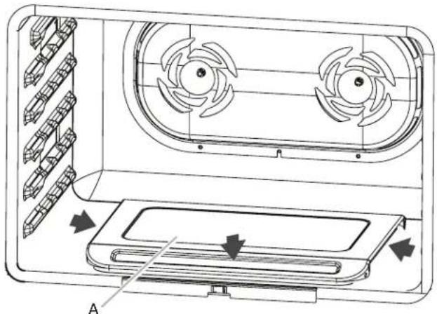
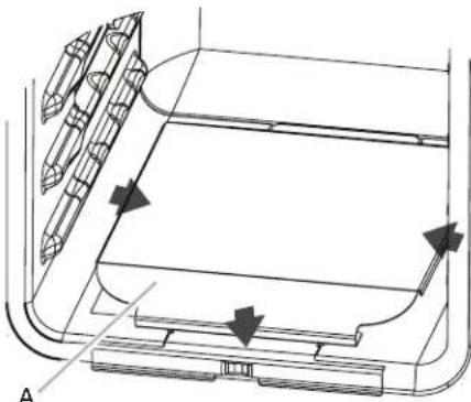
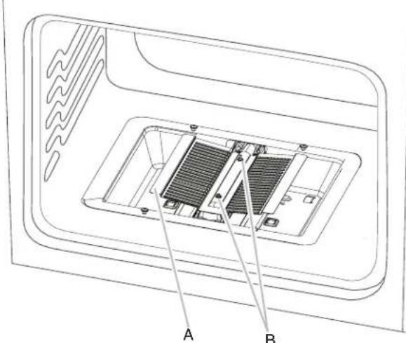
- Slide the bake burner cover to the right or left.
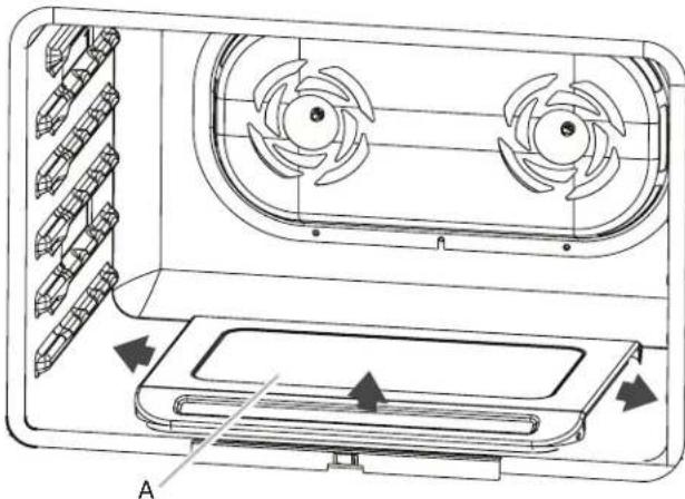
A. Bake burner cover
- Lift up and remove oven bake burner cover, and set aside.
- Using a 1/4'' (6.4 mm) nut driver, unscrew oven baffle nuts and remove oven baffle. Set aside.
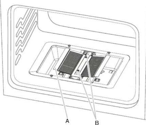
A.Oven baffle
B. Oven baffle nuts
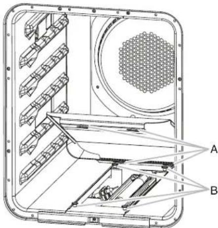
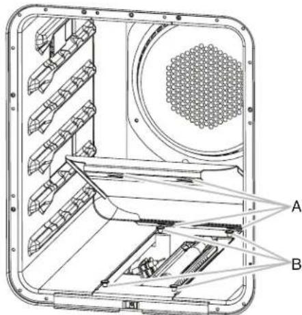
- Remove the oven bake burner screws and oven bake burner. Rotate burner 90^ to the left, and gently lay on its side.
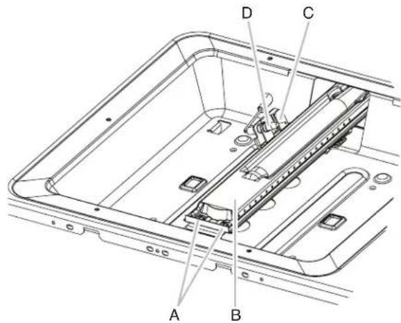
A. Oven bake burner screws
B. Oven bake burner
C. Oven bake burner electrode bracket
D. Oven bake burner electrode
- Lift up clip on the oven bake burner electrode bracket with a finger or flat-blade screwdriver, and pull away the electrode.
A. Oven bake burner electrode bracket
B. Electrode bracket clip
- Pull electrode out of bracket.
A. Grasp electrode here
B. Bracket
- Apply masking tape to the end of a 1/4'' (6.4 mm) nut driver to help hold the gas orifice spud in the nut driver while changing it. Insert nut driver into the gas opening, and press down onto the gas orifice spud, then remove by turning the gas orifice spud counterclockwise and lifting out. Set gas orifice spud aside.

A. Propane gas orifice spud
- Propane gas orifice spuds are stamped with a letter and a number. Install the Number 125 oven bake burner orifice spud.
-
Place Natural gas orifice in plastic parts bag for future use, and keep with package containing literature.
-
Push down on the clip on the electrode bracket.
A. Oven bake burner electrode bracket
B. Electrode bracket clip
- Replace oven bake burner electrode inside bracket.

A. Oven bake burner electrode
B. Oven bake burner electrode bracket
- Reinstall the oven bake burner and oven bake burner screws. See step 4 for illustration.
- Replace oven baffle and oven baffle nuts. The front holes will be aligned, and a click will sound when baffle is seated.
Replace Oven Bake Burner Cover
- Align notches on the oven bake burner cover with shoulder screws in the bottom of the oven.
A. Cover notches (4)
B. Shoulder screws (4)
- Lower cover, and slide to left or right to slide shoulder screws into the narrow ends of the notches, then lock into place.
A. Bake burner cover
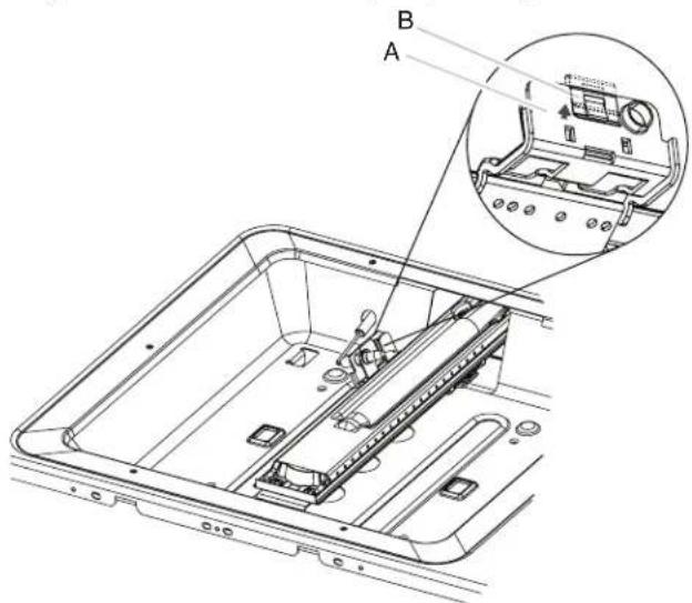
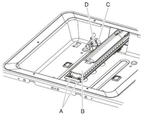
Convert Oven Broil Burner (30" [76.2 cm] and 36" [91.4 cm] models and the right oven cavity on 48" [121.9 cm] models)
- Using a 1/4'' (6.4 mm) nut driver, remove broil burner screw. Set aside with side igniter positioned on the right.
![KITCHENAID KFGC500JSS - Convert Oven Broil Burner (30" [76.2 cm] and 36" [91.4 cm] models and the right oven cavity on 48" [121.9 cm] models) - 1](/content/2026/03/504699/images/03912e45760c0d10cf81939d294d2f28dfb18208380f479d2a36ea01d5b4a9c3.jpg)
A. Broil burner screw
B. Broil burner
C. Broil bumer orifice hole
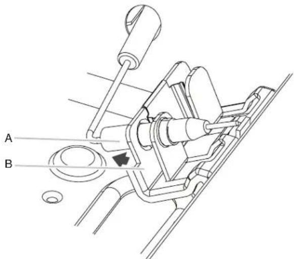
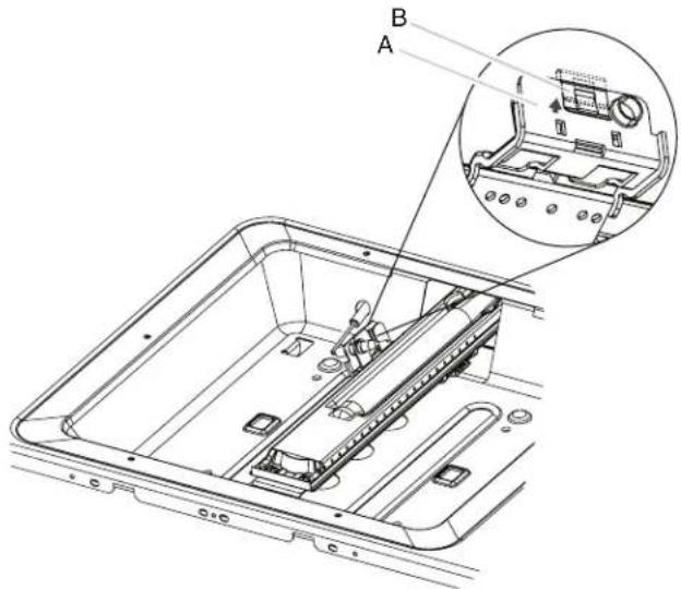
- Pull the broil burner toward you until it slides out of the hole in the oven back, and pull the electrode out of the bracket. The broil burner will hang down in the back of the oven while you change the orifice.
![KITCHENAID KFGC500JSS - Convert Oven Broil Burner (30" [76.2 cm] and 36" [91.4 cm] models and the right oven cavity on 48" [121.9 cm] models) - 2](/content/2026/03/504699/images/7fc4dc78b6f71142c9fd4f6a716c9a672b055d32f6a2edf63d60c74a6f0d1df1.jpg)
A. Grasp electrode here
B. Bracket
![KITCHENAID KFGC500JSS - Convert Oven Broil Burner (30" [76.2 cm] and 36" [91.4 cm] models and the right oven cavity on 48" [121.9 cm] models) - 3](/content/2026/03/504699/images/2374d62a57eedc0eb42c31bd8a1b98fb39ca89e5497f2b54268fbaf8860c26d0.jpg)
Broil burner hanging
in back of oven
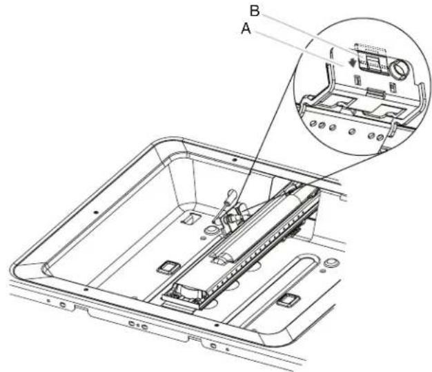
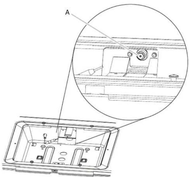
- Apply masking tape to the end of a 1/4'' (6.4 mm) nut driver to help hold the gas orifice spud in the nut driver while changing it. Insert nut driver into the gas opening, and press down onto the gas orifice spud, then remove by turning the gas orifice spud counterclockwise and lifting out. Set gas orifice spud aside.
![KITCHENAID KFGC500JSS - Convert Oven Broil Burner (30" [76.2 cm] and 36" [91.4 cm] models and the right oven cavity on 48" [121.9 cm] models) - 4](/content/2026/03/504699/images/be7b9df715332f87525a227fdb9c43394098681d49526aafe58b2b11dc94e43e.jpg)
A. Oven back
B. Broil burner orifice
C. Broil burner orifice hole
- Propane gas orifice spuds are stamped with a letter and a number. Install the Number 90 oven broil burner orifice spud.
- Place Natural gas orifice in plastic parts bag for future use, and keep with package containing literature.
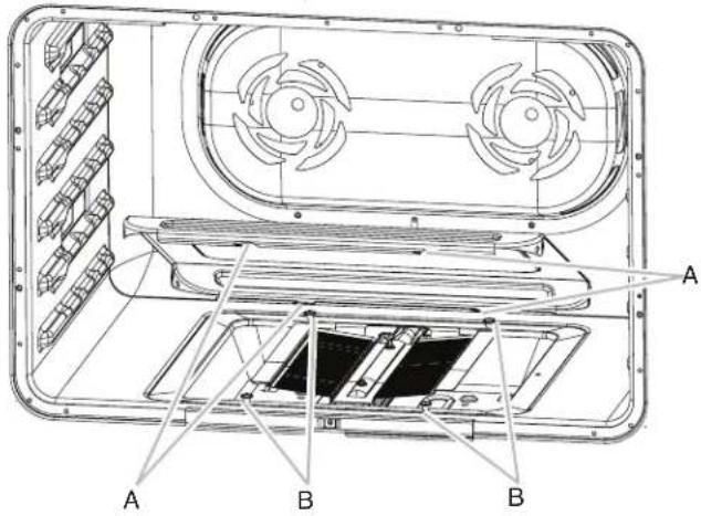
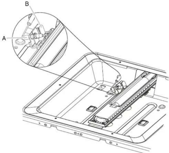
- Replace the broil burner in the hole in the oven back with the broil burner assembly inside the broil burner electrode hole as illustrated.
![KITCHENAID KFGC500JSS - Convert Oven Broil Burner (30" [76.2 cm] and 36" [91.4 cm] models and the right oven cavity on 48" [121.9 cm] models) - 5](/content/2026/03/504699/images/c99fdf8c1fe6c4c1623322e97df1d87e88b2239a4e5bc99b9092e3512e4e46ef.jpg)
A. Broil burner orifice hole
B. Broil burner electrode
C. Broil burner electrode hole
- Reinstall the oven broil burner screw. See step 1 for illustration. The screw is aligned with the hole when a click sounds.
Convert Oven Bake Burner (left oven cavity on 48^ [121.9 cm] models)
- Remove oven racks. See the "Remove Racks" section.
- Remove the oven door. See the "Remove Oven Door" section.
- Slide the bake burner cover to the right or left.
![KITCHENAID KFGC500JSS - Convert Oven Bake Burner (left oven cavity on 48^ [121.9 cm] models) - 1](/content/2026/03/504699/images/1da1a61a9638a91aab4b189951a0c37e4e648afabad4ac52835faf1b6cd1ba96.jpg)
A. Bake burner cover
- Lift up and remove oven bake burner cover, and set aside.
- Remove the oven bake burner screws and oven bake burner, and gently set aside.
![KITCHENAID KFGC500JSS - Convert Oven Bake Burner (left oven cavity on 48^ [121.9 cm] models) - 2](/content/2026/03/504699/images/ca058eeae06364f0a570f7d2041e8240deaa38af0ce938bd1034b151a344a3af.jpg)
A. Oven bake burner
B. Oven bake burner screws
C. Oven bake burner electrode bracket
D. Oven bake burner electrode
- Lift clip up on the oven bake burner electrode bracket with a finger or flat-blade screwdriver.
![KITCHENAID KFGC500JSS - Convert Oven Bake Burner (left oven cavity on 48^ [121.9 cm] models) - 3](/content/2026/03/504699/images/2f3fe109605609cdfffcfc01fa913865fb70490ab5baabce9f144a0170a78ef3.jpg)
A. Oven bake burner electrode bracket
B. Electrode bracket clip
- Pull electrode out of bracket.
![KITCHENAID KFGC500JSS - Convert Oven Bake Burner (left oven cavity on 48^ [121.9 cm] models) - 4](/content/2026/03/504699/images/3eb38c35742bf9cabb8a99a11664b090211c4071dc0408226ac3c471da26c3c4.jpg)
A. Grasp electrode here
B. Bracket
- Apply masking tape to the end of a 1/4'' (6.4 mm) nut driver to help hold the gas orifice spud in the nut driver while changing it. Insert nut driver into the gas opening, and press down onto the gas orifice spud, then remove by turning the gas orifice spud counterclockwise and lifting out. Set gas orifice spud aside.
![KITCHENAID KFGC500JSS - Convert Oven Bake Burner (left oven cavity on 48^ [121.9 cm] models) - 5](/content/2026/03/504699/images/eddb987874ef274ac0cd049bfe025563b1c89d4a2da134f89264eb7de2c9edc4.jpg)
A. Propane gas orifice spud
- Propane gas orifice spuds are stamped with a letter and a number. Install the Number 105 oven bake burner orifice spud.
- Place Natural gas orifice in plastic parts bag for future use, and keep with package containing literature.
- Push down on the clip on the electrode bracket.
![KITCHENAID KFGC500JSS - Convert Oven Bake Burner (left oven cavity on 48^ [121.9 cm] models) - 6](/content/2026/03/504699/images/6bd22eaec000f88e86b4620a02bffe76614f90dc25871e82601a29881a587904.jpg)
A. Oven bake burner electrode bracket
B. Electrode bracket clip
- Replace oven bake burner electrode inside bracket.
![KITCHENAID KFGC500JSS - Convert Oven Bake Burner (left oven cavity on 48^ [121.9 cm] models) - 7](/content/2026/03/504699/images/66adb9f4dacdc880a0cdbdb2d65335ae94bd30606b5480b5e52b350f620d7ff8.jpg)
A. Oven bake burner electrode
B. Oven bake burner electrode bracket
- Reinstall the oven bake burner and oven bake burner screws. See step 5 for illustration.
Replace Oven Bake Burner Cover
- Align rear shoulder screw mounting holes (keyholes) on the oven bake burner cover with shoulder screws in the bottom of the oven.
A. Shoulder screw mounting holes (keyholes)
B. Shoulder screws
- Drop cover and slide to left or right to slide shoulder screws into narrow ends of keyholes, and lock into place.
A. Bake burner cover
Complete Installation
- Refer to the "Make Gas Connection" section for properly connecting the range to the gas supply.
- Refer to the "Electronic Ignition System" section for proper burner ignition, operation, and burner flame adjustments.
IMPORTANT: You may have to adjust the "LO" setting for each range burner. Checking for proper range burner flame is very important. The small inner cone should have a very distinct blue flame 1/4'' (6.4 mm) to 1/2'' (1.3 cm) long. The outer cone is not as distinct as the inner cone. Propane gas flames have a slightly yellow tip.
- Refer to "Complete Installation" in the "Installation Instructions" section of this manual to complete this procedure.
Natural Gas Conversion
WARNING
Tip Over Hazard
A child or adult can tip the range and be killed.
Install anti-tip bracket to floor or wall per installation instructions.
Slide range back so rear range foot is engaged in the slot of the anti-tip bracket.
Re-engage anti-tip bracket if range is moved.
Do not operate range without anti-tip bracket installed and engaged.
Failure to follow these instructions can result in death or serious burns to children and adults.
- Turn the manual shut-off valve to the closed position.
A. To range
B.Shut-off valve (closed position)
C. Gas supply line
- Unplug range or disconnect power.
To Convert Gas Pressure Regulator from Propane to Natural Gas
NOTE: Door must be removed in order to remove or replace kick plate. Refer to the "Remove Door" section.
- Lift the kick plate up and off of the kick plate tab.
A. Kick plate
B. Kick plate tab
C. Kick plate slot
- Gently lay kick plate aside to avoid scratching the stainless steel.
- Locate the gas pressure regulator at the left rear of the range.
A. Gas pressure regulator
- Remove the gas pressure regulator cap by using a large flat-blade screwdriver, turning the regulator cap counterclockwise.
NOTE: Do not remove the spring beneath the cap.
- Turn over the gas pressure regulator cap, and reinstall on the regulator so that the hollow end faces in and the letters "NAT" are visible.
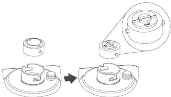
- Tighten the gas pressure regulator cap by using a large flat-blade screwdriver, turning the regulator cap clockwise.
- Test the gas pressure regulator and gas supply line. The regulator must be checked at a minimum 1^ (2.5 cm) water column above the set pressure. The inlet pressure to the regulator should be as follows for operation and checking the regulator setting:
Natural Gas:
Minimum pressure: 5^ (12.7 cm) WCP
Maximum pressure: 14^ (35.6 cm) WCP
Gas Supply Pressure Testing
Gas supply pressure for testing regulator must be at least 1^ (2.5 cm) water column pressure above the manifold pressure shown on the model/serial/rating plate.
Line pressure testing above 1/2 psi (3.5 kPa) gauge (14" [35.6 cm] WCP)
The range and its individual shut-off valve must be disconnected from the gas supply piping system during any pressure testing of that system at test pressures in excess of 1/2 psi (3.5 kPa).
Line pressure testing at 1/2 psi (3.5 kPa) gauge (14" [35.6 cm] WCP) or lower
The range must be isolated from the gas supply piping system by closing its individual manual shut-off valve during any pressure testing of the gas supply piping system at test pressures equal to or less than 1/2 psi (3.5 kPa).
To Convert Surface Burners from Propane to Natural Gas
- If the burner grates are installed, remove them.
- Remove burner cap.
- Remove the burner base by first removing (2) T-20 screws.
Burner
A. Burner cap
B. Screws
C. Burner base
-
Apply masking tape to the end of a 7mm nut driver to help hold the gas orifice spud in the nut driver while changing it. Insert nut driver into the gas opening and press down onto the gas orifice spud and remove by turning the Propane gas orifice spud counterclockwise and lifting out. Set Propane gas orifice spud aside.
-
Replace with correct Natural gas orifice spud. See the "Natural Gas Orifice Spud/Hood Chart." Use the following chart to find the exact orifice spud placement.
Natural Gas Orifice Spud/Hood Chart
NOTE: Refer to serial tag for more information on burner ratings and locations.
Burner orifice spud
A. Size stamp
B. Fuel type stamp (L or N)
- Place Propane gas orifice spuds in plastic parts bag for future use and keep with package containing literature.
-
Replace the burner base and screws. Tighten screws only until burner is snug to cooktop, do not over-tighten.
-
Replace burner cap.
- Repeat steps 2 through 8 for the remaining burners.
Adjusting Simmer Low Setting on Surface Burners for Natural Gas
- Unplug range or disconnect power.
- Using the square bit screwdriver, remove the surface burner control knobs and bezels (Oven control knobs and griddle control knobs do not have to be removed).
- Open the oven door and remove the two screws on each side of the range that hold the control console in place.
NOTE: Make sure to leave the door open or the control console will not rest in the side brackets properly once it is attached.
- Pull up on the control console and let it drop forward into the notched console brackets on each side.
A. Control console bracket
- Locate the appropriate low-turndown screw for the appropriate burner on the given valve. The low-turndown screw for the left rear, right rear, center rear, and center front burner valves (aluminum) is located through the center of the valve stem. The low-turndown screw for the left front and right front burner valves (brass) is located behind the ignition switch on the valve body, left of the stem. To remove the ignition switch cut the wire tie and pull the switch off the valve stem.
A. Aluminum Valve for Left Rear, Right Rear, Center Rear, and Center Front Burners.
B. Brass Valve for Left Front and Right Front Dual Burners.
C.Wire Tie
D. Ignition Switch
A. Low-turndown adjustment screw for Aluminum Valve through center of stem.
B. Low-turndown adjustment screw for Brass Valve.
- With the burner ON (the burner will have to be lit manually with a lighter), and set to simmer LOW, adjust the simmer flame up to the proper BTU level. Using a 1/8'' × 414'' ( 3.2 mm × 10.8 cm ) flat blade screwdriver, turn the simmer low-turndown adjustment screw counterclockwise until the flame height is at, or below, the bottom of the cap. If the flame becomes unstable and flickers or appears to race around the burner, the adjustment is too low and the screw should be adjusted counterclockwise until the flame is stable. Repeat this step for all surface burners.
NOTE: Use a knob to adjust the burner valve.
NOTE: Adjust each burner individually.
- After adjustments are completed, replace the ignition switches onto the valves.
- Lift up on the control console and set it back into place. For a proper fit, the flange of the control console must hook over the lip on the front of the range cooktop.
NOTE: It may be necessary to lift valve stems to align with console holes.
A. Control console flange
B. Front lip of range cooktop
- Check that the control console is flush with the top edge of the range.
A. Flush with range top
- Replace the screws on each side of the control console.
- Replace the bezels using the 2 screws which attach to the valve brackets, making note that there are front and rear bezels and will only attach properly in the correct location on the console.
- Push the Surface Knobs onto the valve stems.
- Replace the burner grates.
Convert Oven Bake Burner (30^ [76.2cm] and 36^ [91.4cm] models and the right oven cavity on 48^ [121.9cm] models)
- Slide the bake burner cover to the right or left.
A. Bake burner cover
- Lift up and remove oven bake burner cover, and set aside.
- Using a 1/4'' (6.4 mm) nut driver, unscrew oven baffle nuts and remove oven baffle. Set aside.
A. Oven baffle
B. Oven baffle nuts
- Remove the oven bake burner screws and oven bake burner. Rotate burner 90^ to the left, and gently lay on its side.
A. Oven bake burner screws
B. Oven bake burner
C. Oven bake burner electrode bracket
D. Oven bake burner electrode
- Lift up clip on the oven bake burner electrode bracket with a finger or flat-blade screwdriver, and pull away the electrode.
A. Oven bake burner electrode bracket
B. Electrode bracket clip
- Pull electrode out of bracket.

A. Grasp electrode here
B. Bracket
- Apply masking tape to the end of a 1/4'' (6.4 mm) nut driver to help hold the gas orifice spud in the nut driver while changing it. Insert nut driver into the gas opening, and press down onto the gas orifice spud, then remove by turning the propane gas orifice spud counterclockwise and lifting out. Set propane gas orifice spud aside.
A. Propane gas orifice spud
- Natural gas orifice spuds are stamped with a letter and a number. Install the Number 189 oven bake burner orifice spud.
-
Place Propane gas orifice in plastic parts bag for future use, and keep with package containing literature.
-
Push down on the clip on the electrode bracket.

A. Oven bake burner electrode bracket
B. Electrode bracket clip
- Replace oven bake burner electrode inside bracket.
A. Oven bake burner electrode
B. Oven bake burner electrode bracket
- Reinstall the oven bake burner and oven bake burner screws. See step 4 for illustration.
- Replace oven baffle and oven baffle nuts. The front holes will be aligned, and a click will sound when baffle is seated.
Replace Oven Bake Burner Cover
- Align notches on the oven bake burner cover with shoulder screws in the bottom of the oven.

A. Cover notches (4)
B. Shoulder screws (4)
- Lower cover, and slide to left or right to slide shoulder screws into the narrow ends of the notches, then lock into place.
A. Bake burner cover
Convert Oven Broil Burner (30" [76.2 cm] and 36" [91.4 cm] models and the right oven cavity on 48" [121.9 cm] models)
- Using a 1/4'' (6.4 mm) nut driver, remove broil burner screw. Set aside with side igniter positioned on the right.
![KITCHENAID KFGC500JSS - Convert Oven Broil Burner (30" [76.2 cm] and 36" [91.4 cm] models and the right oven cavity on 48" [121.9 cm] models) - 1](/content/2026/03/504699/images/8da05bfc8b17f3db61d0fc5cc02b4a4de70d6a1bcfb64323836998f7e9987487.jpg)
A. Broil burner screw
B. Broil burner
C. Broil burner orifice hole
- Pull the broil burner toward you until it slides out of the hole in the oven back, and pull the electrode out of the bracket. The broil burner will hang down in the back of the oven while you change the orifice.
![KITCHENAID KFGC500JSS - Convert Oven Broil Burner (30" [76.2 cm] and 36" [91.4 cm] models and the right oven cavity on 48" [121.9 cm] models) - 2](/content/2026/03/504699/images/dc8c5892a8130ad39b92ed6f47ecfb294bff5e262d30d4dfe1d07113499aefc9.jpg)
A. Grasp electrode here
B. Bracket
![KITCHENAID KFGC500JSS - Convert Oven Broil Burner (30" [76.2 cm] and 36" [91.4 cm] models and the right oven cavity on 48" [121.9 cm] models) - 3](/content/2026/03/504699/images/b7611fd95e5bf5a9bf9433d0ee8c90bafe31e83adada819bb6d262d8a81bd2c0.jpg)
Broil burner hanging
in back of oven
- Apply masking tape to the end of a 1/4'' (6.4 mm) nut driver to help hold the gas orifice spud in the nut driver while changing it. Insert nut driver into the gas opening, and press down onto the gas orifice spud, then remove by turning the Propane gas orifice spud counterclockwise and lifting out. Set Propane gas orifice spud aside.
![KITCHENAID KFGC500JSS - Convert Oven Broil Burner (30" [76.2 cm] and 36" [91.4 cm] models and the right oven cavity on 48" [121.9 cm] models) - 4](/content/2026/03/504699/images/805fc32960a09c2759d33e48c74c7aaca9efc184221d25cf215fe4d3135e031f.jpg)
A. Oven back
B. Broil burner orifice
C. Broil burner orifice hole
- Natural gas orifice spuds are stamped with a letter and a number. Install the Number 148 oven broil burner orifice spud.
- Place Propane gas orifice in plastic parts bag for future use, and keep with package containing literature.
- Replace the broil burner in the hole in the oven back with the broil burner assembly inside the broil burner electrode hole as illustrated.
![KITCHENAID KFGC500JSS - Convert Oven Broil Burner (30" [76.2 cm] and 36" [91.4 cm] models and the right oven cavity on 48" [121.9 cm] models) - 5](/content/2026/03/504699/images/1e894e27a646db5b879359b831e42823d6fdbdc92e7f3054e2400ee2a0613c37.jpg)
A. Broil burner orifice hole
B. Broil burner electrode
C. Broil burner electrode hole
- Reinstall the oven broil burner screw. See step 1 for illustration. The screw is aligned with the hole when a click sounds.
Convert Oven Bake Burner (left oven cavity on 48^ [121.9 cm] models)
- Remove oven racks. See the "Remove Racks" section.
- Remove the oven door. See the "Remove Oven Door" section.
- Slide the bake burner cover to the right or left.
![KITCHENAID KFGC500JSS - Convert Oven Bake Burner (left oven cavity on 48^ [121.9 cm] models) - 1](/content/2026/03/504699/images/0feeaa891c73bfad1def88d2ff7adc766aae624dce5a4f006a98472a98d3c899.jpg)
A. Bake burner cover
- Lift up and remove oven bake burner cover, and set aside.
- Remove the oven bake burner screws and oven bake burner, and gently set aside.
![KITCHENAID KFGC500JSS - Convert Oven Bake Burner (left oven cavity on 48^ [121.9 cm] models) - 2](/content/2026/03/504699/images/49e81dd49ed708b2b3750c0da2aeb7ea156be781796d85f94d2797ce457a88ae.jpg)
A. Oven bake burner
B. Oven bake burner screws
C. Oven bake burner electrode bracket
D. Oven bake burner electrode
- Lift clip up on the oven bake burner electrode bracket with a finger or flat-blade screwdriver.
![KITCHENAID KFGC500JSS - Convert Oven Bake Burner (left oven cavity on 48^ [121.9 cm] models) - 3](/content/2026/03/504699/images/5fd28cf2565383aad90d9bbcba6e7aef1b464fd6ab712486a1be2d8a0826c57c.jpg)
A. Oven bake burner electrode bracket
B. Electrode bracket clip
- Pull electrode out of bracket.
![KITCHENAID KFGC500JSS - Convert Oven Bake Burner (left oven cavity on 48^ [121.9 cm] models) - 4](/content/2026/03/504699/images/e4016a897ce38c7321544f9f1a4ee9261346d4b7661fa3d4684135023ef27cfe.jpg)
A. Grasp electrode here
B. Bracket
- Apply masking tape to the end of a 1/4'' (6.4 mm) nut driver to help hold the gas orifice spud in the nut driver while changing it. Insert nut driver into the gas opening, and press down onto the gas orifice spud, then remove by turning the Propane gas orifice spud counterclockwise and lifting out. Set Propane gas orifice spud aside.
![KITCHENAID KFGC500JSS - Convert Oven Bake Burner (left oven cavity on 48^ [121.9 cm] models) - 5](/content/2026/03/504699/images/261defbb49a8590ce761b7a028d743e56b71606e044598fc998fe0ed3143eeae.jpg)
A. Propane gas orifice spud
- Natural gas orifice spuds are stamped with a letter and a number. Install the Number 154 oven bake burner orifice spud.
-
Place Propane gas orifice in plastic parts bag for future use, and keep with package containing literature.
-
Push down on the clip on the electrode bracket.
![KITCHENAID KFGC500JSS - Convert Oven Bake Burner (left oven cavity on 48^ [121.9 cm] models) - 6](/content/2026/03/504699/images/820d2539c16f60cc8b8b2bd6d7e09895b0990c0bca120f6bef37b0d71d582ac3.jpg)
A. Oven bake burner electrode bracket
B. Electrode bracket clip
- Replace oven bake burner electrode inside bracket.
![KITCHENAID KFGC500JSS - Convert Oven Bake Burner (left oven cavity on 48^ [121.9 cm] models) - 7](/content/2026/03/504699/images/d895cbcf12d76686d36f4bd46a040b0f95afdc872ae28cdcf6d20889424eade1.jpg)
A. Oven bake burner electrode
B. Oven bake burner electrode bracket
- Reinstall the oven bake burner and oven bake burner screws. See step 5 for illustration.
Replace Oven Bake Burner Cover
- Align rear shoulder screw mounting holes (keyholes) on the oven bake burner cover with shoulder screws in the bottom of the oven.
A. Shoulder screw mounting holes (keyholes)
B. Shoulder screws
- Drop cover and slide to left or right to slide shoulder screws into narrow ends of keyholes, and lock into place.
A. Bake burner cover
Complete Installation
- Refer to the "Make Gas Connection" section for properly connecting the range to the gas supply.
- Refer to the "Electronic Ignition System" section for proper burner ignition, operation, and burner flame adjustments.
IMPORTANT: You may have to adjust the "LO" setting for each range burner.
Checking for proper range burner flame is very important. The small inner cone should have a very distinct blue flame 1/4'' (6.4 mm) to 1/2'' (1.3 cm) long. The outer cone is not as distinct as the inner cone. Propane gas flames have a slightly yellow tip. - Refer to "Complete Installation" in the "Installation Instructions" section of this manual to complete this procedure.
SECURITE DE LA CUISINIÈRE
National Fire Protection Association
Batterymarch Park
Quincy, MA 02169-7471
CSA International
8501 East Pleasant Valley Road
Cleveland, Ohio 44131-5575
A. Incorrect
B. Correct
A. Incorrect B. Correct
1/4" (6,4 mm), 3/8" (9,5 mm), 5/16" (7,9 mm)
Marcador o lapicero

K. 5^ (12,7cm)
L. 3" (7,6 cm) en modelos de 30" (76,2 cm).
11" (27,9 cm) en modelos de 36" (91,4 cm).
21" (53,3 cm) en modelos de 48" (121,9 cm).
M. 7 / 2^n (19,0 cm)
N. 9^n (22,9 cm)
O. 6" (15,2 cm)***
National Fire Protection Association
1 Batterymarch Park
Quincy, MA 02169-7471
CSA International
8501 East Pleasant Valley Road
Cleveland, Ohio 44131-5575

- INSTRUCTIONS D'INSTALLATION
- INSTALLATION INSTRUCTIONS.9
- GAS CONVERSIONS. 14
- SECURITE DE LA CUISINIÈRE 30
- EXIGENCES D'INSTALLATION 32
- CONVERSIONS POUR CHANGEMENT DE GAZ. 43
- IMPORTANT :
- Your safety and the safety of others are very important.
- DANGER
- WARNING
- WARNING:
- INSTALLATION REQUIREMENTS
- Tools and Parts
- Tools Needed
- For Propane/Natural Gas Conversions
- Parts Supplied
- Parts Needed
- Location Requirements
- Mobile Home - Additional Installation Requirements
- Mobile Home Installations Require:
- Product Dimensions
- 36" (91.4 cm) models
- 48" (121.9 cm) models
- Cabinet Requirements
- ** If not using ventilation, Minimum Clearances
- Electrical Requirements
- Electrical Shock Hazard
- Gas Supply Requirements
- Explosion Hazard
- Type of Gas
- Natural Gas:
- Propane Gas conversion:
- Gas Supply Line
- Flexible metal appliance connector:
- Gas Pressure Regulator
- Propane Gas:
- Burner Input Rating - Altitude
- Gas Supply Pressure Testing
- Line pressure testing above 1/2 psi (3.5 kPa) gauge (14" [35.6 cm] WCP)
- Line pressure testing at 1/2 psi (3.5 kPa) gauge (14" [35.6 cm] WCP) or lower
- Unpack the Range
- Remove Kick Plate
- Remove Door
- Door Removal
- Replace the Door
- Install Anti-Tip Bracket
- Measurement B:
- Measurement C:
- Make Gas Connection
- Complete Connection
- Verify Anti-Tip Bracket Location
- Install Griddle Tray
- (On griddle models)
- Electronic Ignition System
- Install Burner Caps
- Initial Lighting and Gas Flame Adjustments
- Check Operation of Range Burners
- Flame Height
- Burner
- Level Range
- Install Kick Plate
- Complete Installation
- Check Operation of Oven(s)
- If you need Assistance or Service:
- GAS CONVERSIONS
- Propane Gas Conversion
- Tip Over Hazard
- To Convert Gas Pressure Regulator from Natural Gas to Propane
- To Convert Surface Burners from Natural Gas to Propane
- Propane Gas Orifice Spud/Hood Chart
- Adjusting Simmer Low Setting on Surface Burners for Propane
- Replace Oven Bake Burner Cover
- Convert Oven Broil Burner (30" [76.2 cm] and 36" [91.4 cm] models and the right oven cavity on 48" [121.9 cm] models)
- Convert Oven Bake Burner (left oven cavity on 48^ [121.9 cm] models)
- Natural Gas Conversion
- To Convert Gas Pressure Regulator from Propane to Natural Gas
- To Convert Surface Burners from Propane to Natural Gas
- Natural Gas Orifice Spud/Hood Chart
- Adjusting Simmer Low Setting on Surface Burners for Natural Gas
- SECURITE DE LA CUISINIÈRE
Brand : KITCHENAID
Model : KFGC500JSS
Category : Cooker