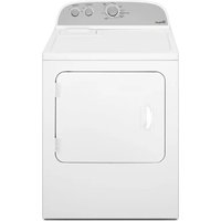
YWED7120HC - Tumble drier WHIRLPOOL - Free user manual and instructions
Find the device manual for free YWED7120HC WHIRLPOOL in PDF.

User questions about YWED7120HC WHIRLPOOL
0 question about this device. Answer the ones you know or ask your own.
Ask a new question about this device
Download the instructions for your Tumble drier in PDF format for free! Find your manual YWED7120HC - WHIRLPOOL and take your electronic device back in hand. On this page are published all the documents necessary for the use of your device. YWED7120HC by WHIRLPOOL.
USER MANUAL YWED7120HC WHIRLPOOL
Dryer Installation and Care Instructions Manual
Installation clearances....6
ELECTRICAL REQUIREMENTS -
U.S.A. ONLY 7
ELECTRIC DRYER POWER HOOKUP-
CANADA ONLY....8
Electrical requirements....8
Electrical requirements....8
Gas supply requirements....9
Gas type 9
Gas supply line 9
Gas supply connection requirements.....9
Burner input requirements ......9
Dryer gas pipe....10
INSTALL LEVELING LEGS....10
MAKE ELECTRICAL CONNECTION
U.S.A. ONLY 10
Electrical Connection....10
Power Supply Cord Connection....11
Direct Wire Connection....13
MAKE GAS CONNECTION -
U.S.A. AND CANADA....16
VENTING....17
Venting Requirements....17
Plan Vent System....18
Install vent system....19
CONNECT INLET HOSES....19
CONNECT VENT 20
LEVEL DRYER....21
COMPLETE INSTALLATION CHECKLIST ...22
DRYER DOOR (ON SOME MODELS) .....22
DOOR REVERSAL (ON SOME MODELS)....23
DRYER CARE 27
CHECK YOUR VENT SYSTEM FOR
GOOD AIR FLOW 28
SÉCURITÉ DE LA SÉCHEUSE....30
EXIGENCES D'INSTALLATION ....33
Raccordement direct....41
EFFECTUER LE RACCORDEMENT
AU GAZ - É.-U. ET CANADA....44
Exigences concernant l'évacuation .....45
ÉVACUATION 45
Your safety and the safety of others are very important.
We have provided many important safety messages in this manual and on your appliance. Always read and obey all safety messages.

This is the safety alert symbol.
This symbol alerts you to potential hazards that can kill or hurt you and others.
All safety messages will follow the safety alert symbol and either the word "DANGER" or "WARNING."
These words mean:
DANGER
You can be killed or seriously injured if you don't immediately follow instructions.
WARNING
You can be killed or seriously injured if you don't follow instructions.
All safety messages will tell you what the potential hazard is, tell you how to reduce the chance of injury, and tell you what can happen if the instructions are not followed.

WARNING
Fire Hazard
Failure to follow safety warnings exactly could result in serious injury, death, or property damage.
Do not install a booster fan in the exhaust duct.
Install all clothes dryers in accordance with the installation instructions of the manufacturer of the dryer.
IMPORTANT: The gas installation must conform with local codes, or in the absence of local codes, with the National Fuel Gas Code, ANSI Z223.1/NFPA 54, or the Natural Gas and Propane Installation Code, CSA B149.1.
The dryer must be electrically grounded in accordance with local codes, or in the absence of local codes, with the National Electrical Code, ANSI/NFPA 70, or the Canadian Electrical Code, Part 1, CSA C22.1.

WARNING - "Risk of Fire"
- Clothes dryer installation must be performed by a qualified installer.
- Install the clothes dryer according to the manufacturer's instructions and local codes.
- Do not install a clothes dryer with flexible plastic venting materials or flexible metal (foil type) duct. If flexible metal duct is installed, it must be of a specific type identified by the appliance manufacturer as suitable for use with clothes dryers. Flexible venting materials are known to collapse, be easily crushed, and trap lint. These conditions will obstruct clothes dryer airflow and increase the risk of fire.
- To reduce the risk of severe injury or death, follow all installation instructions.
- Save these instructions.
In the State of Massachusetts, the following installation instructions apply:
■ Installations and repairs must be performed by a qualified or licensed contractor, plumber, or gas fitter qualified or licensed by the State of Massachusetts.
■ Acceptable Shut-off Devices: Gas Cocks and Ball Valves installed for use shall be listed.
■ A flexible gas connector, when used, must not exceed 4 feet (121.9 cm).
IMPORTANT SAFETY INSTRUCTIONS
WARNING: To reduce the risk of fire, electric shock, or injury to persons when using your appliance, follow basic precautions, including the following:
- Read all instructions before using the appliance.
■ Do not dry articles that have been previously cleaned in, washed in, soaked in, or spotted with gasoline, dry-cleaning solvents, or other flammable or explosive substances, as they give off vapors that could ignite or explode.
■ Do not allow children to play on or in the appliance. Close supervision of children is necessary when the appliance is used near children.
■ Before the appliance is removed from service or discarded, remove the door to the drying compartment.
■ Do not reach into the appliance if the drum is moving.
■ Do not install or store this appliance where it will be exposed to the weather.
■ Do not tamper with controls.
■ Do not repair or replace any part of the appliance or attempt any servicing unless specifically recommended in the user-maintenance instructions or in published user-repair instructions that you understand and have the skills to carry out.
■ Do not use fabric softeners or products to eliminate static unless recommended by the manufacturer of the fabric softener or product.
■ Do not use heat to dry articles containing foam rubber or similarly textured rubber-like materials.
■ Clean lint screen before or after each load.
- Keep area around the exhaust opening and adjacent surrounding areas free from the accumulation of lint, dust, and dirt.
■ The interior of the appliance and exhaust duct should be cleaned periodically by qualified service personnel.
■ Do not place items exposed to cooking oils in your dryer. Items contaminated with cooking oils may contribute to a chemical reaction that could cause a load to catch fire. To reduce the risk of fire due to contaminated loads, the final part of a tumble dryer cycle occurs without heat (cool down period). Avoid stopping a tumble dryer before the end of the drying cycle unless all items are quickly removed and spread out so that the heat is dissipated.
■ Do not use replacement parts that have not been recommended by the manufacturer (e.g. parts made at home using a 3D printer).
■ See the Installation Instructions for grounding requirements and installation.
■ Do not install a booster fan in the exhaust duct.
NOTE: The booster fan warning does not apply to clothes dryers intended to be installed in a multiple clothes dryer system, with an engineered exhaust duct system that is installed per the clothes dryer manufacturer's guidelines.
SAVE THESE INSTRUCTIONS
IMPORTANT SAFETY INSTRUCTIONS
When discarding or storing your old clothes dryer, remove the door.
SAVE THESE INSTRUCTIONS
INSTALLATION REQUIREMENTS
TOOLS AND PARTS
Gather the required tools and parts before starting installation. Read and follow the instructions provided with any tools listed here.
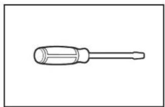
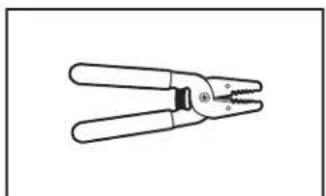
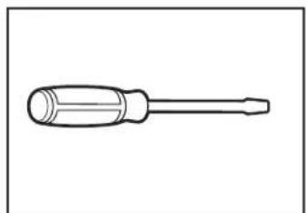
Tools needed for all installations:
natural_image
Line drawing of a screwdriver with a cylindrical head and threaded shaft (no text or symbols)
natural_image
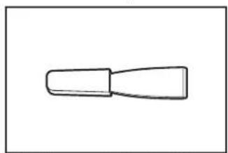
Line drawing of an adjustable wrench (no text or symbols)Flat-blade screwdriver Adjustable wrench that opens to 1" or hex-head socket wrench
natural_image
Simple line drawing of a rectangular object with three circular holes, no text or symbols present.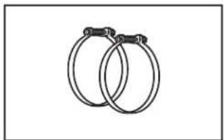
natural_image
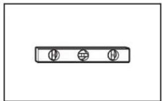
Two interlocked rings with metal clips attached (no text or symbols)Level Vent clamps
natural_image
Simple line drawing of a tool or component with no text or symbols
natural_image
Two line drawings of laboratory pipettes: a cylindrical tool and a micrometer (no text or labels)Plastic putty knife Caulking gun and compound (for installing new exhaust vent)
natural_image
Line drawing of a pliers with handle and blade (no text or symbols)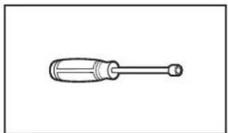
natural_image
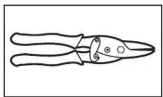
Line drawing of a screwdriver with a cylindrical head and threaded shaft (no text or symbols)Tin snips (new vent installations)
natural_image
Simple line drawing of a screwdriver (no text or symbols)1/4" nut driver (recommended)
natural_image
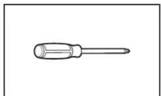
Line drawing of a pair of pliers with metal handles and a screw (no text or symbols)2 Phillips screwdriver Wire stripper (direct wire installations)
natural_image
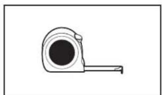
Simple line drawing of a tape measure (no text or symbols)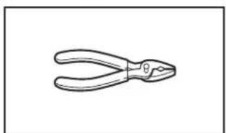
natural_image
Line drawing of a pair of pliers (no text or symbols)Tape measure Pliers
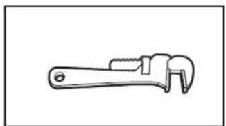
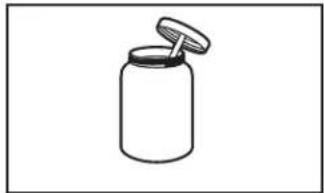
Tools needed for gas installations:
natural_image
Line drawing of a adjustable wrench (no text or symbols)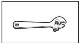
natural_image
Line drawing of an adjustable wrench (no text or symbols)8" or 10" pipe wrench 8" or 10" adjustable wrench (for gas connections)
natural_image
Simple line drawing of a jar with a lid (no text or symbols)Pipe-joint compound resistant to propane gas
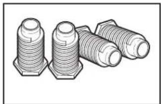
Parts supplied (all models):
natural_image
Illustration of three threaded hex nuts with different thread patterns (no text or symbols)Leveling legs (4)
Parts needed (steam models):
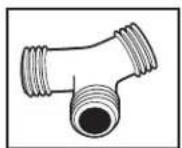
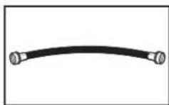
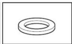
Short inlet hose Rubber washer (4)
"Y" connector
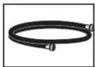
Inlet hose
If using a power supply cord:
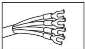
Use a UL listed power supply cord kit marked for use with clothes dryers. The kit should contain:
■ A UL listed 30 A power supply cord, rated 120/240 V minimum, with a temperature rating of 140°F (60°C) minimum. The cord should be type SRD or SRDT and be at least 4 ft (1.22 m) long. The wires that connect to the dryer must end in ring terminals or spade terminals with upturned ends.
■ A UL listed strain relief
Parts needed: (Not supplied with dryer)
Check local codes. Check existing electrical supply and venting. See "Electrical Requirements" and "Venting Requirements" before purchasing parts.
Mobile home installations require metal exhaust system hardware available for purchase from the dealer from whom you purchased your dryer. For further information, please refer to the "Assistance or Service" section in your "Quick Reference Guide."
WARNING

Explosion Hazard
Keep flammable materials and vapors, such as gasoline, away from dryer.
Place dryer at least 18 inches (46 cm) above the floor for a garage installation.
Failure to do so can result in death, explosion, or fire.
You will need:
■ A location allowing for proper exhaust installation. See “Venting Requirements.”
■ A separate 15 A or 20 A circuit needed for gas dryers and 30 A circuit needed for electric dryers.
If using power supply cord, a grounded electrical outlet located within 2 ft (610 mm) of either side of dryer. See "Electrical Requirements."
■ Floor must support dryer weight of 200 lbs (90.7 kg). Also consider weight of companion appliance.
■ Level floor with maximum slope of 1" (25 mm) under entire dryer. If slope is greater than 1" (25 mm), clothes may not tumble properly and automatic sensor cycles may not operate correctly.
■ For garage installation, place dryer at least 18" (460 mm) above floor.
■ Steam models only: Cold water faucets located within 4 ft (1.2 m) of the water fill valves, and water pressure of 20-100 psi (137.9-689.6 kPa). You may use your washer's water supply by purchasing the necessary parts noted in "Parts needed."
IMPORTANT: Do not operate, install, or store dryer where it will be exposed to water, weather, or at temperatures below 45^ F ( 7^ C). Lower temperatures may cause dryer not to shut off at end of automatic sensor cycles, resulting in longer drying times.
NOTE: No other fuel-burning appliance can be installed in the same closet as a dryer.
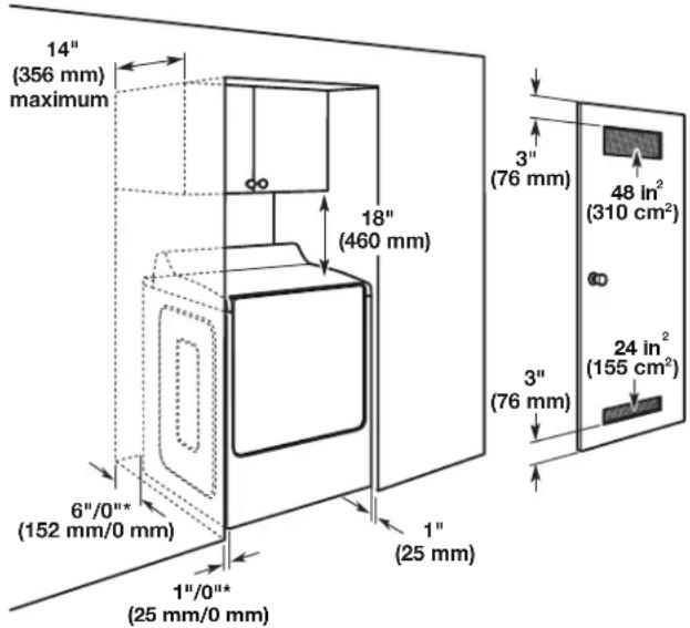
INSTALLATION CLEARANCES
For each arrangement, consider allowing more space for ease of installation and servicing, spacing for companion appliances and clearances for walls, doors, and floor moldings. Space must be large enough to allow door to fully open. Add spacing on all sides of dryer to reduce noise transfer. If a closet door or louvered door is installed, top and bottom air openings in door are required.
Check code requirements. Some codes limit, or do not permit, installation of the dryer in garages, closets, mobile homes, or sleeping quarters. Contact your local building inspector.
Spacing for recessed area or closet installation
The dimensions shown are for the recommended spacing allowed.
■ Additional spacing should be considered for ease of installation and servicing.
■ Additional clearances might be required for wall, door, and floor moldings.
■ Additional spacing of 1" (25 mm) on all sides of the dryer is recommended to reduce noise transfer.
■ For closet installation, with a door, minimum ventilation openings in the top and bottom of the door are required. Louvered doors with equivalent ventilations openings are acceptable.
■ Companion appliance spacing should also be considered.
text_image
14" (356 mm) maximum 18" (460 mm) 6"/0"* (152 mm/0 mm) 1"/0"* (25 mm/0 mm) 1" (25 mm) 3" (76 mm) 48 in² (310 cm²) 3" (76 mm) 24 in² (155 cm²)*Recommended/Minimum spacing
Mobile home - Additional installation requirements:
This dryer is suitable for mobile home installations.
The installation must conform to the Manufactured Home Construction and Safety Standard, Title 24 CFR, Part 3280 (formerly the Federal Standard for Mobile home construction and Safety, Title 24, HUD Part 280) or Standard CAN/CSA-Z240 MH.
Mobile home installations require:
All dryers:
■ Metal exhaust system hardware, available for purchase from your dealer. For further information, see “Assistance or Service” section in your “Quick Reference Guide.”
■ Special provisions must be made in mobile homes to introduce outside air into dryer. Openings (such as a nearby window) should be at least twice as large as dryer exhaust opening.
For gas dryers mobile home installations:
■ Mobile Home Installation Hold-down Kit is available to order. For further information, see “Assistance or Service” section in your “Quick Reference Guide.”
It is your responsibility:
■ To contact a qualified electrical installer.
■ To be sure that the electrical connection is adequate and in conformance with the National Electrical Code, ANSI/NFPA 70 - latest edition and all local codes and ordinances.
The National Electrical Code requires a 4-wire power supply connection for homes built after 1996, dryer circuits involved in remodeling after 1996, and all mobile home installations.
A copy of the above code standards can be obtained from: National Fire Protection Association, One Batterymarch Park, Quincy, MA 02269.
To supply the required 3 or 4-wire, single phase, 120/240 V, 60 Hz, AC only electrical supply (or 3 or 4-wire, 120/208 V electrical supply, if specified on the serial/rating plate) on a separate 30 A circuit, fused on both sides of the line. Connect to an individual branch circuit. Do not have a fuse in the neutral or grounding circuit.
■ Do not use an extension cord.
If codes permit and a separate ground wire is used, it is recommended that a qualified electrician determine that the ground path is adequate.
Electrical Connection
To properly install your dryer, you must determine the type of electrical connection you will be using and follow the instructions provided for it here.
This dryer is manufactured ready to install with a 3-wire electrical supply connection. The neutral bond conductor is permanently connected to the neutral conductor (white wire) within the dryer. If the local electrical codes require the use of a ground-fault circuit interrupter, then a 4 wire electrical supply connection is required. The neutral bond conductor must be removed from the external ground connector (green screw), and secured under the neutral terminal (center or white wire) of the terminal block. When the neutral bond conductor is secured under the neutral terminal (center or white wire) of the terminal block, the dryer cabinet is isolated from the neutral conductor.
If local codes do not permit the connection of a neutral bond wire to the neutral wire, see "Optional 3-wire connection" section.
■ A 4-wire power supply connection must be used when the appliance is installed in a location where grounding through the neutral conductor is prohibited. Grounding through the neutral is prohibited for (1) new branch-circuit installations, (2) mobile homes, (3) recreational vehicles, and (4) areas where local codes prohibit grounding through the neutral conductors.
If using a power supply cord:
Use a UL listed power supply cord kit marked for use with clothes dryers. The kit should contain:
■ A UL listed 30 A power supply cord, rated 120/240 V minimum, with a temperature rating of 140°F (60°C) minimum. The cord should be type SRD or SRDT, and be at least 4 ft (1.22 m) long. The wires that connect to the dryer must end in ring terminals or spade terminals with upturned ends.
■ A UL listed strain relief.
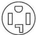
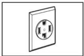
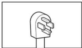
If your outlet looks like this:

4-wire receptacle (14-30R)
Then choose a 4-wire power supply cord with ring or spade terminals and UL listed strain relief. The 4-wire power supply cord, at least 4 ft (1.22 m) long, must have 4 10-gauge solid copper wires and match a 4-wire receptacle of NEMA Type 14-30 R. The ground wire (ground conductor) may be either green or bare. The neutral conductor must be identified by a white cover.
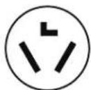
If your outlet looks like this:

3-wire receptacle (10-30R)
Then choose a 3-wire power supply cord with ring or spade terminals and UL listed strain relief. The 3-wire power supply cord, at least 4 ft (1.22 m) long, must have 3 10-gauge solid copper wires and match a 3-wire receptacle of NEMA Type 10-30 R.
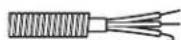
If connecting by direct wire:
Power supply cable must match power supply (4-wire or 3-wire) and be:
■ Flexible armored cable or nonmetallic sheathed copper cable (with ground wire), covered with flexible metallic conduit. All current-carrying wires must be insulated.
■ 10-gauge solid copper wire (do not use aluminum) at least 5 ft (1.52 m) long.
GROUNDING INSTRUCTIONS
■ For a grounded, cord-connected dryer:
This dryer must be grounded. In the event of malfunction or breakdown, grounding will reduce the risk of electric shock by providing a path of least resistance for electric current. This dryer uses a cord having an equipment-grounding conductor and a grounding plug. The plug must be plugged into an appropriate outlet that is properly installed and grounded in accordance with all local codes and ordinances
■ For a permanently connected dryer:
This dryer must be connected to a grounded metal, permanent wiring system, or an equipment-grounding conductor must be run with the circuit conductors and connected to the equipment-grounding terminal or lead on the dryer.
WARNING: Improper connection of the equipment-grounding conductor can result in a risk of electric shock. Check with a qualified electrician or service representative or personnel if you are in doubt as to whether the dryer is properly grounded. Do not modify the plug on the power supply cord: if it will not fit the outlet, have a proper outlet installed by a qualified electrician.
SAVE THESE INSTRUCTIONS
ELECTRIC DRYER POWER HOOKUP- CANADA ONLY
ELECTRICAL REQUIREMENTS
WARNING
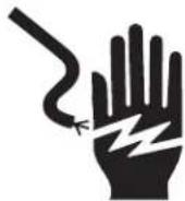
Electrical Shock Hazard
Plug into a grounded 4 prong outlet.
Failure to do so can result in death or electrical shock.
It is your responsibility:
■ To contact a qualified electrical installer.
■ To be sure that the electrical connection is adequate and in conformance with Canadian Electrical Code, C22.1-latest edition and all local codes. A copy of above codes standard may be obtained from: Canadian Standards Association, 178 Rexdale Blvd., Toronto, ON M9W 1R3 CANADA.
■ To supply the required 4-wire, single phase, 120/240 V, 60 Hz, AC only electrical supply on a separate 30 A circuit, fused on both sides of the line. A time-delay fuse or circuit breaker is recommended. Connect to an individual branch circuit.
This dryer is equipped with a UL listed and/or CSA International Certified Power Cord intended to be plugged into a standard 14-30R wall receptacle. The cord is 5 ft (1.52 m) long. Be sure wall receptacle is within reach of dryer's final location.
4-wire receptacle (14-30R)
For further information, please reference service numbers located in "Assistance or Service" section of your "Quick Reference Guide."
GROUNDING INSTRUCTIONS
■ For a grounded, cord-connected dryer:
This dryer must be grounded. In the event of malfunction or breakdown, grounding will reduce the risk of electric shock by providing a path of least resistance for electric current.
This dryer uses a cord having an equipment-grounding conductor and a grounding plug. The plug must be plugged into an appropriate outlet that is properly installed and grounded in accordance with all local codes and ordinances.
■ For a permanently connected dryer:
This dryer must be connected to a grounded metal, permanent wiring system, or an equipment-grounding conductor must be run with the circuit conductors and connected to the equipment-grounding terminal or lead on the dryer.
WARNING: Improper connection of the equipment-grounding conductor can result in a risk of electric shock. Check with a qualified electrician or service representative or personnel if you are in doubt as to whether the dryer is properly grounded. Do not modify the plug on the power supply cord: if it will not fit the outlet, have a proper outlet installed by a qualified electrician.
SAVE THESE INSTRUCTIONS
GAS DRYER POWER HOOKUP - U.S.A. AND CANADA
ELECTRICAL REQUIREMENTS
WARNING

Electrical Shock Hazard
Plug into a grounded 3 prong outlet.
Do not remove ground prong.
Do not use an adapter.
Do not use an extension cord.
Failure to follow these instructions can result in death, fire, or electrical shock.
■ 120 V, 60 Hz, AC only, 15 A or 20 A fused electrical supply is required. A time-delay fuse or circuit breaker is recommended. It is also recommended that a separate circuit serving only this dryer be provided.
GROUNDING INSTRUCTIONS
■ For a grounded, cord-connected dryer:
This dryer must be grounded. In the event of malfunction or breakdown, grounding will reduce the risk of electric shock by providing a path of least resistance for electric current. This dryer uses a cord having an equipment-grounding conductor and a grounding plug. The plug must be plugged into an appropriate outlet that is properly installed and grounded in accordance with all local codes and ordinances.
■ For a permanently connected dryer:
This dryer must be connected to a grounded metal, permanent wiring system, or an equipment-grounding conductor must be run with the circuit conductors and connected to the equipment-grounding terminal or lead on the dryer.
WARNING: Improper connection of the equipment-grounding conductor can result in a risk of electric shock. Check with a qualified electrician or service representative or personnel if you are in doubt as to whether the dryer is properly grounded. Do not modify the plug on the power supply cord: if it will not fit the outlet, have a proper outlet installed by a qualified electrician.
SAVE THESE INSTRUCTIONS
WARNING
Explosion Hazard
Use a new CSA International approved gas supply line.
Install a shut-off valve.
Securely tighten all gas connections.
If connected to propane, have a qualified person make sure gas pressure does not exceed 13" (330 mm) water column.
Examples of a qualified person include:
licensed heating personnel,
authorized gas company personnel, and authorized service personnel.
Failure to do so can result in death, explosion, or fire.
GAS TYPE
Natural Gas:
This dryer is equipped for use with Natural gas. It is certified by UL for use with propane gas with appropriate conversion.
- Your dryer must have the correct burner for the type of gas in your home. Burner information is located on the rating plate in the door well of your dryer. If this information does not agree with the type of gas available, contact your dealer or call the phone numbers referenced in the “Assistance or Service” section of your “Quick Reference Guide.”
Propane Gas Conversion:
IMPORTANT: Conversion must be made by a qualified technician.
No attempt shall be made to convert the dryer from the gas specified on the model/serial rating plate for use with a different gas without consulting your gas company.
GAS SUPPLY LINE
Option 1 (Recommended Method)
Flexible stainless steel gas connector:
■ If local codes permit, use a new flexible stainless steel gas connector (Design Certified by the American Gas Association or CSA International) to connect your dryer to the rigid gas supply line. Use an elbow and a 3/8" flare x 3/8" NPT adapter fitting between the stainless steel gas connector and the dryer gas pipe as needed to prevent kinking.
Option 2 (Alternate Method)
Approved aluminum or copper tubing
■ Must include 1/8" NPT minimum plugged tapping accessible for test gauge connection, immediately upstream of the gas connection to the dryer.
■ 1/2" IPS pipe is recommended.
■ 3/8" approved aluminum or copper tubing is acceptable for lengths under 20 ft (6.1 m) if local codes and gas supplier permit.
■ If you are using Natural gas, do not use copper tubing.
■ Lengths over 20 ft (6.1 m) should use larger tubing and a different size adapter fitting.
If your dryer has been converted to use LP gas, 3/8" propane compatible copper tubing can be used. If the total length of the supply line is more than 20 ft (6.1 m), use larger pipe.
NOTE: Pipe-joint compounds that resist the action of propane gas must be used. Do not use TEFLON ^®† tape.
■ Must include shut-off valve.
In the U.S.A.:
An individual manual shut-off valve must be installed within 6 ft (1.8 m) of the dryer in accordance with the National Fuel Gas Code, ANSI Z223.1. The location should be easy to reach for opening and closing.
In Canada:
An individual manual shut-off valve must be installed in accordance with the B149.1, Natural Gas and Propane Installation Code. It is recommended that an individual manual shutoff valve be installed within 6 ft (1.8 m) of the dryer. The location should be easy to reach for opening and closing.
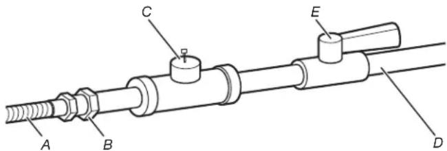
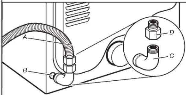
text_image
A B C D EA. 3/8" flexible gas connector
B. 3/8" pipe to flare adapter fitting
C. 1/8" NPT minimum plugged tapping
D. 1/2" NPT gas supply line
E. Gas shutoff valve
GAS SUPPLY CONNECTION REQUIREMENTS
Use an elbow and a 3/8" flare x 3/8" NPT adapter fitting between the flexible gas connector and the dryer gas pipe, as needed to avoid kinking.
■ Use only pipe-joint compound. Do not use TEFLON ^®† tape.
This dryer must be connected to the gas supply line with a listed flexible gas connector that complies with the standard for connectors for gas appliances, ANSI Z21.24 or CSA 6.10.
BURNER INPUT REQUIREMENTS
Elevations above 2,000 ft (610 m):
■ When installed above 2,000 ft (610 m) a 4% reduction of the burner BTU rating shown on the model/serial number plate is required for each 1,000 ft (305 m) increase in elevation.
Gas supply pressure testing
■ The dryer must be disconnected from the gas supply piping system during pressure testing at pressures greater than 1/2 psi.
^ TEFLON is a registered trademark of Chemours.
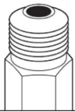
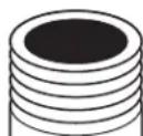
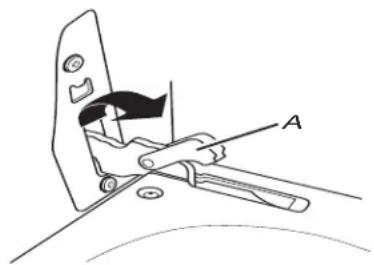
DRYER GAS PIPE
■ The gas pipe that comes out through the rear of your dryer has a 3/8" male pipe thread.
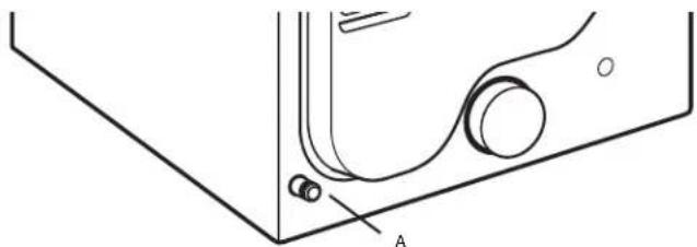
natural_image
Technical line drawing of a mechanical component with labeled point A (no text or symbols beyond label)A. 3/8" NPT dryer pipe
NOTE: For a garage installation, the gas pipe height must be an additional 18" (460 mm) from the floor.
INSTALL LEVELING LEGS
WARNING
Excessive Weight Hazard
Use two or more people to move and install dryer.
Failure to do so can result in back or other injury.
1. Prepare dryer for leveling legs
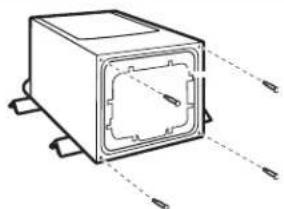
natural_image
Technical line drawing of a rectangular electronic component with internal cavity and mounting base (no text or symbols)Firmly grasp dryer body (not console panel) and gently lay dryer down on back cardboard corner posts.
IMPORTANT: If laying dryer on its back, use the cardboard corner posts the dryer was packed with to avoid damaging the back of the dryer.
2. Screw in leveling legs
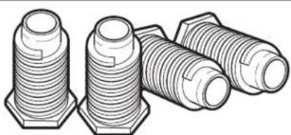
natural_image
Illustration of three different types of threaded fasteners or bolts (no text or symbols present)Using a wrench and tape measure, screw leveling legs into leg holes until bottom of foot is approximately 1" (25 mm) from bottom of dryer.
Now stand the dryer on its feet. Slide the dryer until it is close to its final location. Leave enough room to connect the exhaust vent.
For mobile home use
Gas dryers must be securely fastened to the floor. Mobile home installations require a MobileHome Installation Hold-down Kit. For ordering information please reference the "Quick Reference Guide."
MAKE ELECTRICAL CONNECTION - U.S.A. ONLY
ELECTRICAL CONNECTION
Power Supply Cord:
WARNING
Fire Hazard
Use a new UL listed 30 amp power supply cord.
Use a UL listed strain relief.
Disconnect power before making electrical connections.
Connect neutral wire (white or center wire) to center terminal (silver).
Ground wire (green or bare wire) must be connected to green ground connector.
Connect remaining 2 supply wires to remaining 2 terminals (gold).
Securely tighten all electrical connections.
Failure to do so can result in death, fire, or electrical shock.
Electrical Connection Options:
1. Choose electrical connection type

Power supply cord 4-wire receptacle (NEMA Type 14-30R): Go to Power Supply Cord Connection.
Power supply cord 3-wire receptacle (NEMA Type 10-30R): Go to Power Supply Cord Connection.

4-wire direct connection: Go to Direct Wire Connection.
3-wire direct connection: Go to Direct Wire Connection.
NOTE: If local codes do not permit connection of a cabinet-ground conductor to neutral wire, go to "Optional 3-wire connection." This connection may be used with either a power supply cord or a direct wire connection.
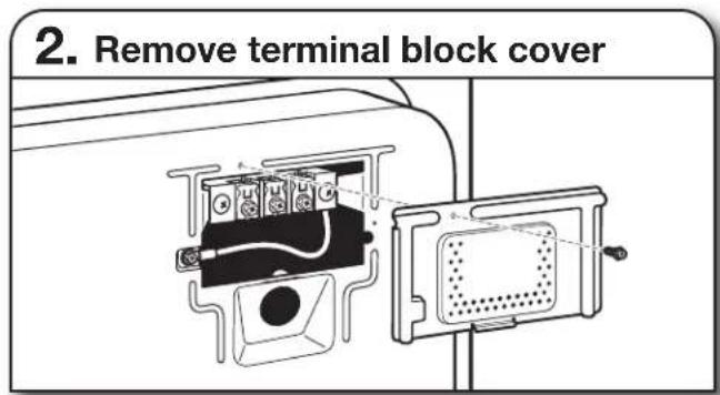
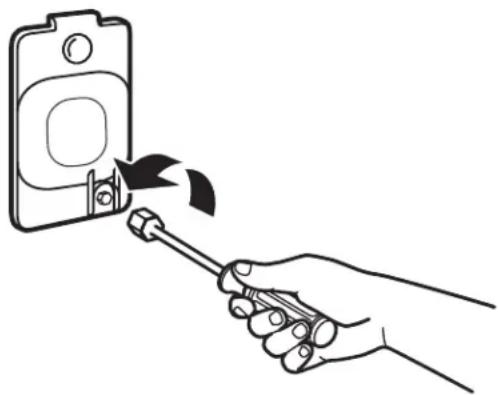
text_image
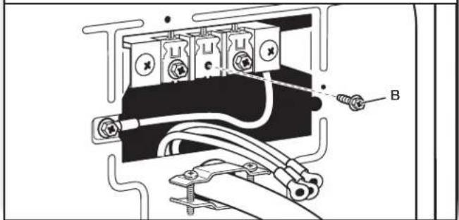
2. Remove terminal block coverRemove hold-down screw and terminal block cover.
POWER SUPPLY CORD CONNECTION
Power Supply Cord Strain Relief
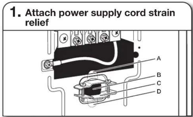
text_image
1. Attach power supply cord strain relief A B C DRemove the screws from a 3/4" (19 mm) UL Listed strain relief. Put the tabs of the two clamp sections (C) into the hole below the terminal block opening (B) so that one tab is pointing up (A) and the other is pointing down (D), and hold in place. Tighten strain relief screws just enough to hold the two clamp sections (C) together.
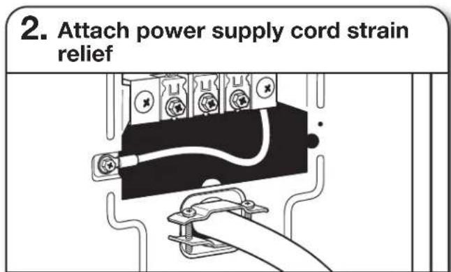
text_image
2. Attach power supply cord strain reliefPut power supply cord through the strain relief. Be sure that the wire insulation on the power supply cord is inside the strain relief. The strain relief should have a tight fit with the dryer cabinet and be in a horizontal position. Tighten the strain relief against the power supply cord. Do not overtighten the strain relief screws.
If your outlet looks like this:
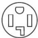
Power supply cord 4-wire receptacle (NEMA Type 14-30R):
Go to "4-Wire Power Supply Cord Connection".

Power supply cord 3-wire receptacle (NEMA Type 10-30R):
Go to "3-Wire Power Supply Cord Connection."
4-Wire Power Supply Cord Connection
IMPORTANT: A 4-wire connection is required for mobile homes and where local codes do not permit the use of 3-wire connections.
natural_image
Simple line drawing of a wall socket with four pins (no text or symbols)4-wire receptacle (NEMA type 14-30R)
natural_image
Simple line drawing of a three-pin electrical plug (no text or symbols)4-prong plug
natural_image
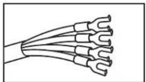
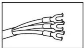
Line drawing of a multi-core cable with multiple U-shaped connectors (no text or symbols)Spade terminals with upturned ends
natural_image
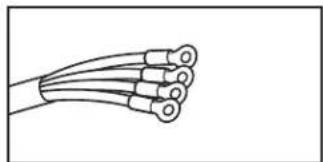
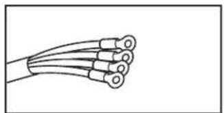
Line drawing of a multi-core cable with multiple coaxial connectors (no text or symbols)Ring terminals

text_image
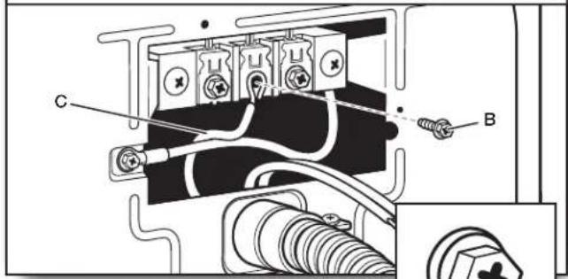
1. Prepare ground wire appliance installation E B ARemove center terminal block screw (B). Remove neutral bond wire (E) from external ground conductor screw (A).
- Connect neutral bond wire and neutral wire
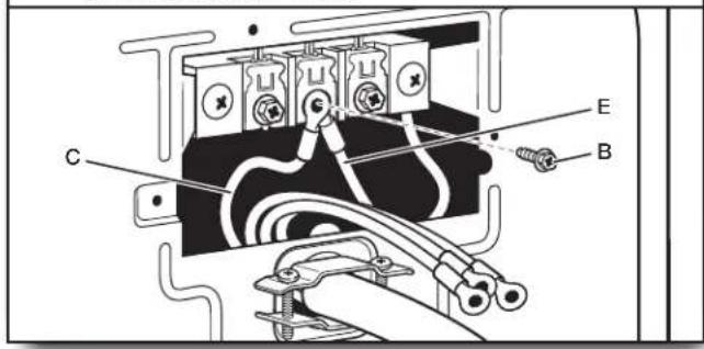
text_image
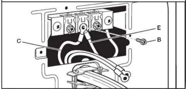
Technical diagram of an electrical contactor with labeled components A, B, and CConnect neutral bond wire (E) and neutral wire (white) (C) of power supply cord under center terminal block screw (B). Tighten screw.
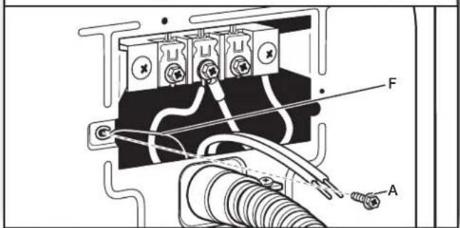
- Connect ground wire
text_image
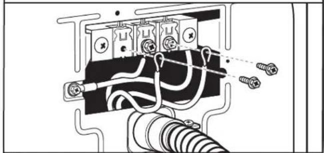
F AConnect ground wire (F) (green or bare) of power supply cord to external ground conductor screw (A). Tighten screw.
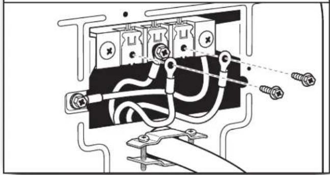
- Connect remaining wires
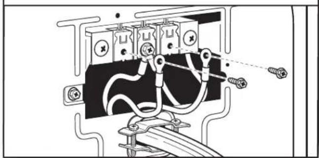
natural_image
Technical diagram of an electrical contactor with wiring and mounting bracket (no text or labels)Connect remaining wires to outer terminal block screws. Tighten screws. Finally, reinsert tab of terminal block cover into slot of dryer rear panel. Secure cover with hold-down screw. Now, go to "Venting Requirements."
3-Wire Power Supply Cord Connection:
Use where local codes permit connecting cabinet-ground conductor to neutral wire.
natural_image
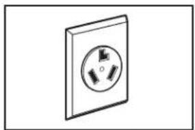
Simple line drawing of a wall socket with three leads (no text or symbols)3-wire receptacle (NEMA type 10-30R)
natural_image
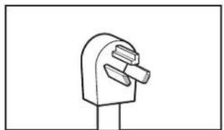
Simple line drawing of a push-button switch (no text or symbols)3-prong plug
natural_image
Line drawing of a multi-core cable with multiple leads (no text or symbols)Spade terminals with upturned ends
natural_image
Line drawing of a multi-core cable with multiple leads (no text or symbols)Ring terminals
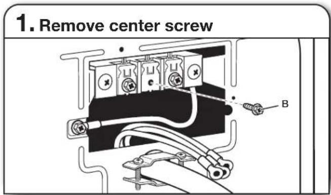
text_image
1. Remove center screw BRemove center terminal block screw (B).
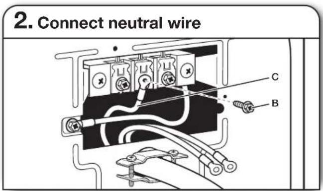
text_image
2. Connect neutral wire C BConnect neutral wire (white or center) (C) of power supply cord to center terminal block screw (B). Tighten screw.
- Connect remaining wires
natural_image
Pure electrical circuit lines without any symbolsConnect remaining wires to outer terminal block screws. Tighten screws. Finally, reinsert tab of terminal block cover into slot of dryer rear panel. Secure cover with hold-down screw. Now, go to "Venting Requirements."
DIRECT WIRE CONNECTION
WARNING

Fire Hazard
Use 10 gauge copper wire.
Use a UL listed strain relief.
Disconnect power before making electrical connections.
Connect neutral wire (white or center wire) to center terminal (silver).
Ground wire (green or bare wire) must be connected to green ground connector.
Connect remaining 2 supply wires to remaining 2 terminals (gold).
Securely tighten all electrical connections.
Failure to do so can result in death, fire, or electrical shock.
Direct Wire Strain Relief:
1. Attach direct wire strain relief
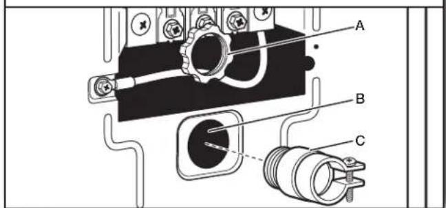
text_image
Technical diagram of an electrical contactor with labeled components A, B, and CUnscrew the removable conduit connector (A) and any screws from a 3/4" (19 mm) UL Listed strain relief.
Put the threaded section of the strain relief (C) through the hole below the terminal block opening (B). Reaching inside the terminal block opening, screw the removable conduit connector (A) onto the strain relief threads.
- Attach direct wire cable to strain relief
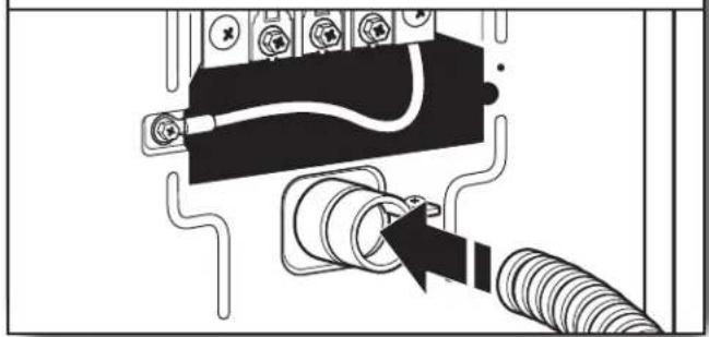
natural_image
Pure electrical circuit lines without any symbolsPut direct wire cable through the strain relief. The strain relief should have a tight fit with the dryer cabinet and be in a horizontal position. Tighten strain relief screw against the direct wire cable.
If your wiring looks like this:
4-wire direct connection:
Go to "4-Wire Direct Connection" on this page.
3-wire direct connection:
Go to "3-Wire Direct Connection" on page 11.
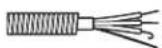
4-wire Direct Wire Connection:
IMPORTANT: A 4-wire connection is required for mobile homes and where local codes do not permit 3-wire connections.
- Prepare your 4-wire cable for direct connection
text_image
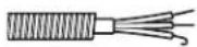
1" (25 mm) 5" (127 mm)Direct wire cable must have 5 ft (1.52 m) of extra length so dryer may be moved if needed.
Strip 5" (127 mm) of outer covering from end of cable, leaving bare ground wire at 5" (127 mm). Cut 1½" (38 mm) from remaining 3 wires. Strip insulation back 1" (25 mm). Shape ends of wires into hooks.
- Prepare bond wire appliance installation
text_image
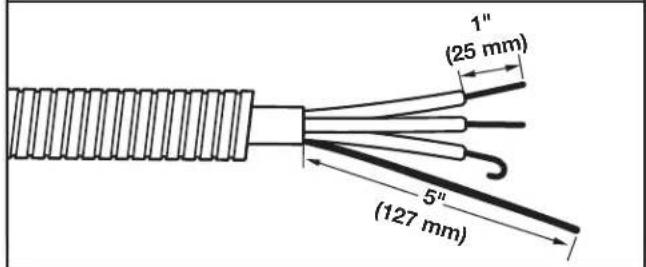
Technical diagram of an electrical component with labeled parts A, B, and E, showing wiring connections and mounting points.Remove center terminal block screw (B). Remove neutral bond wire (E) from external bond conductor screw (A).
- Connect neutral bond wire and neutral wire
text_image
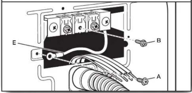
Technical diagram of an electrical component with labeled parts C, E, and BConnect neutral bond wire (E) and place hooked end (hook facing right) of neutral wire (white or center wire) (C) of direct wire cable under center screw of terminal block (B). Squeeze hooked ends together and tighten screw.

- Connect ground wire
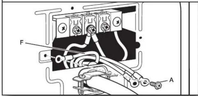
text_image
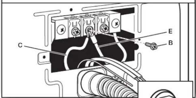
Technical diagram of an electrical component with labeled parts A and F, showing wiring and mounting points.Connect ground wire (green or bare) (F) of direct wire cable to external ground conductor screw (A). Tighten screw.
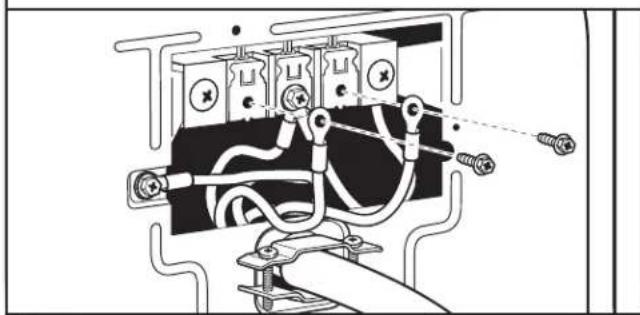
- Connect remaining wires
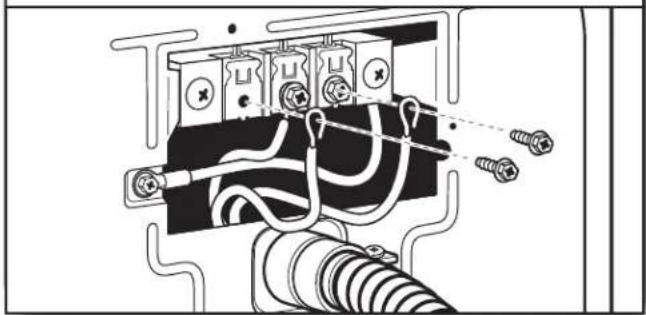
natural_image
Pure electrical circuit lines without any symbolsPlace hooked ends of remaining direct wire cable wires under outer terminal block screws (hooks facing right). Squeeze hooked ends together and tighten screws. Finally, reinsert tab of terminal block cover into slot of dryer rear panel. Secure cover with hold-down screw. Now, go to "Venting Requirements."
3-wire Direct Wire Connection
Use where local codes permit connecting cabinet-ground conductor to neutral wire.
- Prepare your 3-wire cable for direct connection
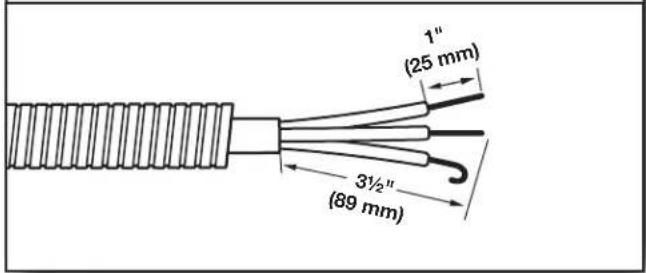
text_image
1" (25 mm) 3½" (89 mm)Direct wire cable must have 5 ft (1.52 m) of extra length so dryer may be moved if needed.
Strip 3½" (89 mm) of outer covering from end of cable. Strip insulation back 1" (25 mm). If using 3-wire cable with ground wire, cut bare wire even with outer covering. Shape wire ends into hooks.
- Remove center screw
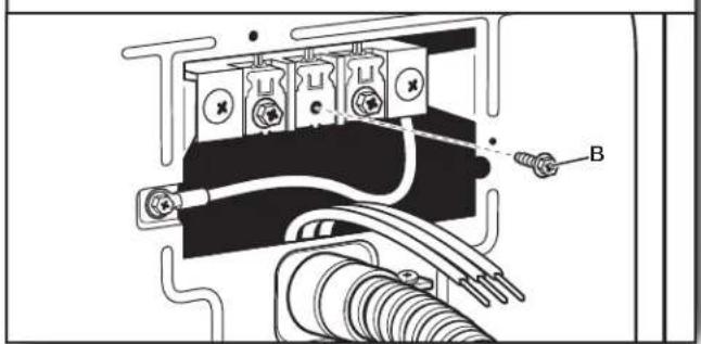
natural_image
Technical diagram of an electrical connector with labeled parts (no readable text or symbols)Remove center terminal block screw (B).
- Connect neutral wire
text_image
Technical diagram of an electrical component with labeled parts C and B, showing wiring and connections.Place hooked end of neutral wire (white or center) (C) of direct wire cable under center terminal block screw (B). Squeeze hooked end together. Tighten screw.
- Connect neutral bond wire and neutral wire
text_image
Technical diagram of an electrical contactor with labeled components A, B, and CConnect neutral bond wire (E) and neutral wire (white or center wire) (C) of power supply cord or cable under center terminal block screw (B). Tighten screw.
- Connect remaining wires
natural_image
Pure electrical circuit lines without any symbolsPlace hooked ends of remaining direct wire cable wires under outer terminal block screws (hooks facing right). Squeeze hooked ends together and tighten screws. Finally, reinsert tab of terminal block cover into slot of dryer rear panel. Secure cover with hold-down screw. Now, go to "Venting Requirements."
- Connect remaining wires
natural_image
Pure electrical circuit lines without any symbolsConnect remaining wires to outer terminal block screws. Tighten screws.
Optional 3-wire Connection:
You must verify with a qualified electrician that this grounding method is acceptable before connecting.
- Prepare bond wire appliance installation
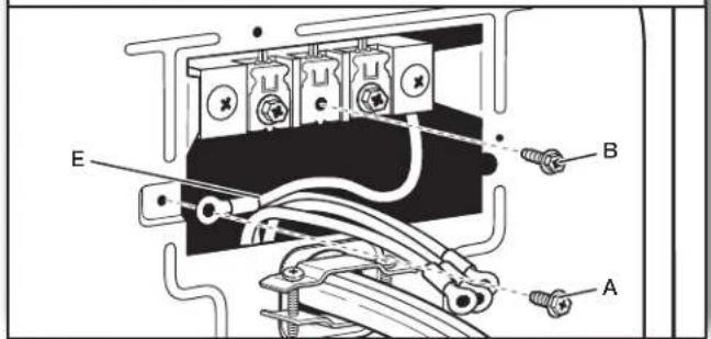
text_image
E B ARemove center terminal block screw (B). Remove neutral bond wire (E) from external bond conductor screw (A).
- Connect external ground wire
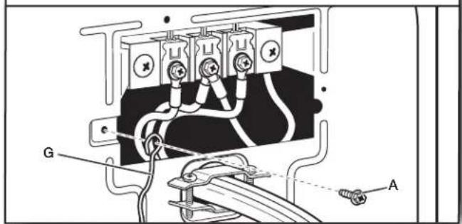
text_image
G AConnect a separate copper ground wire (G) from the external ground conductor screw (A) to an adequate ground. Finally, reinsert tab of terminal block cover into slot of dryer rear panel. Secure cover with hold-down screw. Now, go to "Venting Requirements."
WARNING
Explosion Hazard
Use a new CSA International approved gas supply line.
Install a shut-off valve.
Securely tighten all gas connections.
If connected to propane, have a qualified person make sure gas pressure does not exceed 13" (330 mm) water column.
Examples of a qualified person include:
licensed heating personnel, authorized gas company personnel, and authorized service personnel.
Failure to do so can result in death, explosion, or fire.
1. Connect gas supply to dryer
Flared male fitting
Non-flared male fitting
Remove red cap from gas pipe. Using a wrench to tighten, connect gas supply to dryer. Use pipe-joint compound on threads of all non-flared male fittings. If flexible metal tubing is used, be sure there are no kinks.
NOTE: For propane gas connections, you must use pipe-joint compound resistant to action of propane gas. Do not use TEFLON ^®† tape.
2. Plan pipe fitting connection
text_image
A B D CA. 3/8" flexible gas connector
B. 3/8" dryer pipe
C. 3/8" to 3/8" pipe elbow
D. 3/8" pipe-to-flare adapter fitting
A combination of pipe fittings must be used to connect dryer to existing gas line. Recommended connection is shown. Your connection may be different, according to supply line type, size, and location.
3. Open shut-off valve
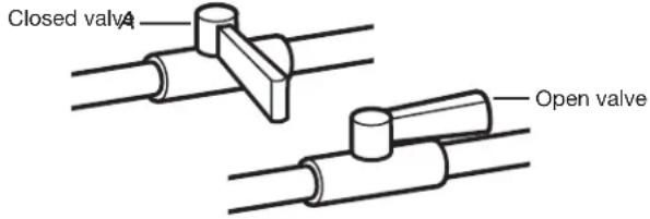
text_image
Closed valve Open valveOpen shut-off valve in supply line; valve is open when handle is parallel to gas pipe. Then, test all connections by brushing on an approved noncorrosive leak-detection solution. Bubbles will show a leak. Correct any leaks found.
VENTING REQUIREMENTS
WARNING

Fire Hazard
Use a heavy metal vent.
Do not use a plastic vent.
Do not use a metal foil vent.
Failure to follow these instructions can result in death or fire.
WARNING: To reduce the risk of fire, this dryer MUST BE EXHAUSTED OUTDOORS.
IMPORTANT: Observe all governing codes and ordinances. Dryer exhaust must not be connected into any gas vent, chimney, wall, ceiling, attic, crawl space, or a concealed space of a building. Only rigid or flexible metal vent shall be used for exhausting.
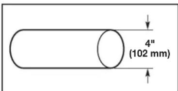
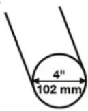
text_image
4" (102 mm)4" (102 mm) heavy metal exhaust vent
■ Only a 4" (102 mm) heavy metal exhaust vent and clamps may be used.
■ Do not use plastic or metal foil vent.
Rigid metal vent:
■ Recommended for best drying performance and to avoid crushing and kinking.
Flexible metal vent: (Acceptable only if accessible to clean)
■ Must be fully extended and supported in final dryer location.
■ Remove excess to avoid sagging and kinking that may result in reduced airflow and poor performance.
■ Do not install in enclosed walls, ceilings, or floors.
■ The total length should not exceed 74 ft (2.4 m).
■ The length of flexible metal vent used must be included in the overall vent system design as shown in the “Vent System Charts.”
NOTE: If using an existing vent system, clean lint from entire length of the system and make sure exhaust hood is not plugged with lint. Replace plastic or metal foil vents with rigid metal or flexible metal vents. Review Vent System Chart and, if necessary, modify existing vent system to achieve best drying performance.
Exhaust hoods:
■ Must be at least 12" (305 mm) from ground or any object that may obstruct exhaust (such as flowers, rocks, bushes, or snow).
Recommended Styles:
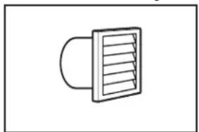
natural_image
Simple line drawing of a vent or airflow device with a curved handle and rectangular panel (no text or symbols)Louvered Hood
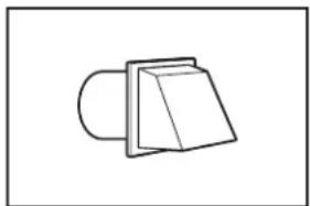
natural_image
Simple line drawing of a 3D object resembling a folded paper or bracket (no text or symbols)Box Hood
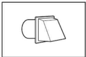
Acceptable Style:
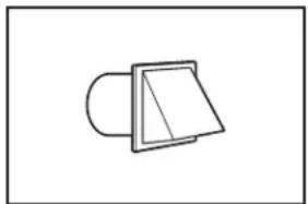
natural_image
Simple line drawing of a folded paper or plastic sheet with a triangular cutout (no text or symbols)Angled Hood
Elbows:
■ 45° elbows provide better airflow than 90° elbows.
Recommended Styles:
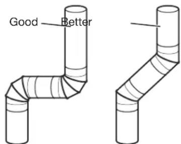
text_image
Good BetterClamps:
■ Use clamps to seal all joints.
■ Exhaust vent must not be connected or secured with screws or other fastening devices that extend into interior of duct and catch lint. Do not use duct tape.
natural_image
Simple line drawing of a belt drive mechanism with two rings and a belt (no text or symbols)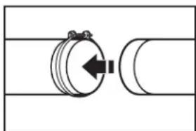
natural_image
Pure mechanical diagram showing a cylindrical component connected to a curved pipe (no text or symbols)Vent products can be purchased from your dealer. For more information, see “Assistance or Service” section in your “Quick Reference Guide.”
PLAN VENT SYSTEM
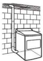
Recommended exhaust installations:
Typical installations vent the dryer from the rear of the dryer. Other installations are possible.
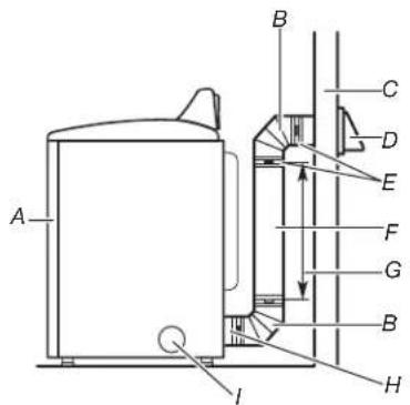
text_image
A B C D E F G B H IA. Dryer
B. Elbow
C. Wall
D. Exhaust hood
E. Clamps
F. Rigid metal or flexible metal vent
G. Vent length necessary to connect elbows
H. Exhaust outlet
I. Optional side exhaust outlet
Optional exhaust installations:
WARNING

Fire Hazard
Cover unused exhaust holes with a manufacturer's exhaust cover kit.
Contact your local dealer.
Failure to follow these instructions can result in death, fire, electrical shock, or serious injury.
If you prefer, dryer may be converted to exhaust through the bottom and sides. You must contact your local dealer to have dryer converted.
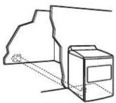
natural_image
Simple line drawing of a box and a paper airplane (no text or symbols)A B C
A. Standard rear offset exhaust installation
B. Left or right side exhaust installation
C. Bottom exhaust installation
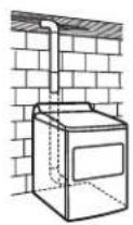
Special provisions for mobile homes:
Exhaust vent must be securely fastened to a noncombustible portion of mobile home and must not terminate beneath the mobile home. Terminate exhaust vent outside.
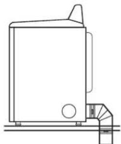
natural_image
Line drawing of a mechanical device with a cylindrical component and a side pipe fitting (no text or symbols)Mobile Home Exhaust installation
Determine vent path:
■ Select route that will provide straightest and most direct path outdoors.
■ Plan installation to use fewest number of elbows and turns.
■ When using elbows or making turns, allow as much room as possible.
■ Bend vent gradually to avoid kinking.
■ Use as few 90° turns as possible.
Determine vent length and elbows needed for best drying performance:
■ Use following Vent System Chart to determine type of vent material and hood combinations acceptable to use.
NOTE: Do not use vent runs longer than those specified in Vent System Chart. Exhaust systems longer than those specified will:
■ Shorten life of dryer.
■ Reduce performance, resulting in longer drying times and increased energy usage.
The Vent System Charts provide venting requirements that will help achieve best drying performance.
| Vent System Chart | ||
| Number of 90° turns or elbows | Type of vent | Angled hoods |
| 0 | Rigid metal 64 ft (20 m) | |
| 1 | Rigid metal 54 ft (16.5 m) | |
| 2 | Rigid metal 44 ft (13.4 m) | |
| 3 | Rigid metal 35 ft (10.7 m) | |
| 4 | Rigid metal 27 ft (8.2 m) | |
NOTE: Bottom exhaust installations have a 90^ turn inside the dryer. To determine maximum exhaust length, add one 90^ turn to the charts.
INSTALL VENT SYSTEM
1. Install exhaust hood
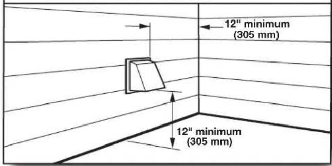
text_image
12" minimum (305 mm) 12" minimum (305 mm)Install exhaust hood and use caulking compound to seal exterior wall opening around exhaust hood.
2. Connect vent to exhaust hood
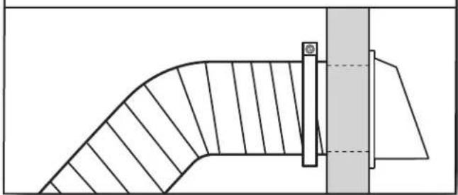
natural_image
Technical line drawing of a curved mechanical component with hatched fill and a vertical guide bar (no text or symbols)Vent must fit over the exhaust hood. Secure vent to exhaust hood with 4" (102 mm) clamp. Run vent to dryer location using straightest path possible. Avoid 90° turns. Use clamps to seal all joints. Do not use duct tape, screws, or other fastening devices that extend into interior of vent to secure vent, because they can catch lint.
CONNECT INLET HOSES
For non-steam models, skip to "Connect Vent."
The dryer must be connected to the cold water faucet using the new inlet hoses. Do not use old hoses.
1. Turn cold water off, remove and replace rubber washer
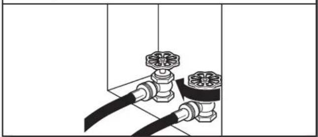
natural_image
Pure diagram of two pipe fittings with floral valves, no text or symbols presentTurn cold water faucet off and remove washer inlet hose.
Remove old rubber washer from inlet hose and replace with new rubber washer.
2. Attach short hose and "Y" connector
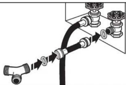
natural_image
Diagram of a pipe connection with valve fittings and tubing, showing fluid flow direction (no text or labels)Attach 2 ft (0.6 m) inlet hose to cold water faucet. Screw on coupling by hand until it is seated on faucet. Then attach "Y" connector to male end of the 2 ft (0.6 m) inlet hose. Screw on coupling by hand until it is seated on connector.
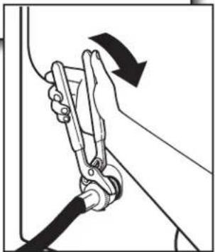
3. Tighten couplings

natural_image
Mechanical assembly diagram showing a hand operating a valve with hoses and a rotating arrow (no text or symbols)Using pliers, tighten the couplings with additional two-thirds turn.
NOTE: Do not overtighten. Damage to the coupling can result.
4. Attach long hose to "Y" connector and tighten couplings
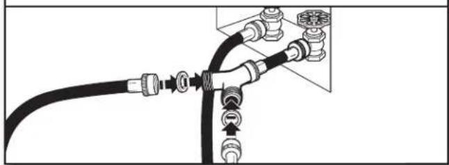
natural_image
Pure electrical circuit lines without any symbolsAttach dryer 5 ft (1.5 m) inlet hose ends to the "Y" connector. Attach washer cold inlet hose to other side of "Y" connector. Screw on coupling by hand until it is seated on connector. Using pliers, tighten the couplings an additional two-thirds turn.
NOTE: Do not overtighten. Damage to the coupling can result.
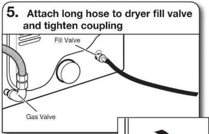
Attach other end of long hose to fill valve at bottom of dryer back panel. Screw on coupling by hand until it is seated on fill valve connector. Using pliers, tighten the couplings an additional two-thirds turn.
NOTE: Do not overtighten. Damage to the coupling can result.
natural_image
Illustration of a person using a cable to lift a car, showing motion direction (no text or symbols)- Turn on cold water faucet
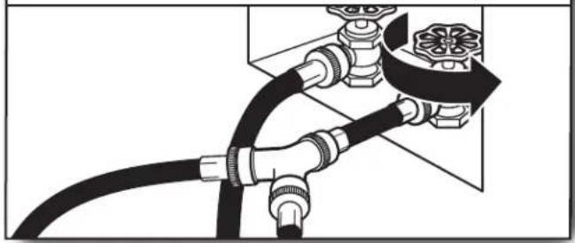
natural_image
Pure diagram of a pipe fitting with valves and fittings, no text or symbols presentCheck that the water faucet is turned on.
- Check for leaks
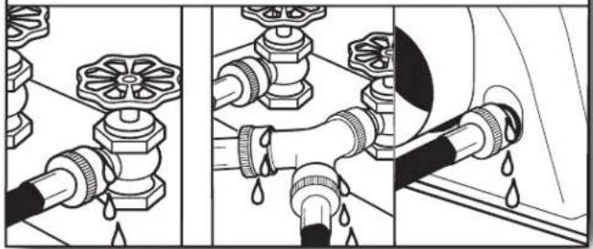
natural_image
Three-panel illustration showing pipe fittings and water droplets during a procedure (no text or symbols)Check for leaks around "Y" connector, faucets, and hoses.
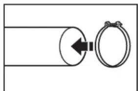
CONNECT VENT
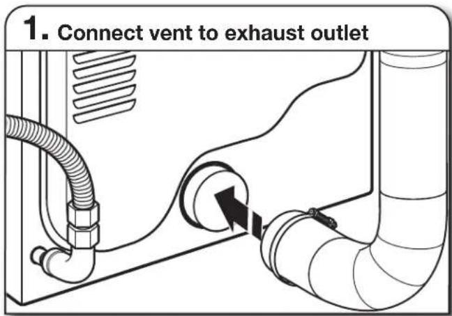
Using a 4" (102 mm) clamp, connect vent to exhaust outlet in dryer. If connecting to existing vent, make sure vent is clean. Dryer vent must fit over dryer exhaust outlet and inside exhaust hood. Check that vent is secured to exhaust hood with a 4" (102 mm) clamp.
- Move dryer to final location
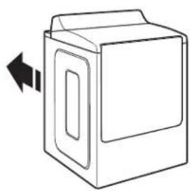
natural_image
Line drawing of a box with a door and lid, showing a left-pointing arrow (no text or symbols)Move dryer to final location. Avoid crushing or kinking vent.
LEVEL DRYER
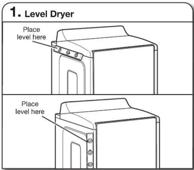
text_image
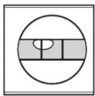
1. Level Dryer Place level here Place level hereCheck levelness of dryer from side to side. Repeat from front to back.
NOTE: The dryer must be level for the moisture sensing system to operate correctly.
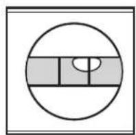
Not Level
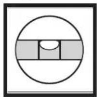
natural_image
Simple geometric diagram with a circle, three shaded rectangles, and a semicircle inside (no text or symbols)LEVEL
Not Level

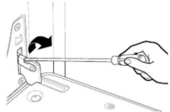
text_image
2. Adjust leveling legsIf dryer is not level, prop up using a wood block. Use wrench to adjust legs up or down, and check again for levelness.
text_image
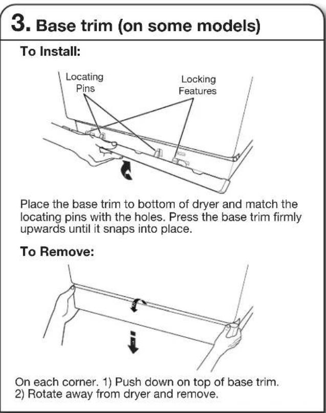
3. Base trim (on some models) To Install: Locating Pins Locking Features Place the base trim to bottom of dryer and match the locating pins with the holes. Press the base trim firmly upwards until it snaps into place. To Remove: On each corner. 1) Push down on top of base trim. 2) Rotate away from dryer and remove.COMPLETE INSTALLATION CHECKLIST
- Check that all parts are now installed. If there is an extra part, go back through steps to see what was skipped.
- Check that you have all of your tools.
■ Dispose of/recycle all packaging materials. - Check dryer's final location. Be sure vent is not crushed or kinked.
- Check that dryer is level. See "Level Dryer."
■ Remove film on console and any tape remaining on dryer.
■ Wipe dryer drum interior thoroughly with a damp cloth to remove any dust.
Read "Dryer Use" in your "Quick Reference Guide."
Electric Models:
For power supply cord installation, plug into a grounded outlet. For direct wire installation, turn on Power.
Gas Models:
- Check that gas supply is on.
Check for leaks.
Steam Models Only:
- Be sure the water faucets are on.
- Check for leaks around "Y" connector, faucet, and hoses.
If you live in a hard water area, use of a water softener is recommended to control the buildup of scale through the water system in the dryer. Over time, the buildup of lime scale may clog different parts of the water system, which will reduce product performance. Excessive scale buildup may lead to the need for certain part replacement or repair.
All Models:
■ Select a Timed Dry heated cycle, and start dryer. Do not select Air Only Temperature setting.
If dryer will not start, check the following:
■ Controls are set in a running or "ON" position. Start button has been pushed firmly.
■ Dryer is plugged into an outlet and/or electrical supply is connected.
■ Household fuse is intact and tight, or circuit breaker has not tripped.
■ Dryer door is closed.
This dryer automatically runs an installation diagnostic routine at the start of its first cycle.
If your dryer heater is not turning on, then you might have power supply problem in your house. You will receive L2 code for this problem. "See Troubleshooting."
If your Airflow screen reads "Check Vent", your dryer vent may be crushed or blocked. See "Troubleshooting."
NOTE: You may notice an odor when dryer is first heated. This odor is common when heating element is first used. The odor will go away.
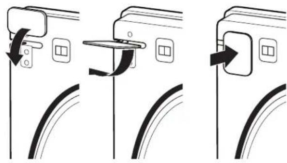
DRYER DOOR (ON SOME MODELS)
For normal dryer use, it is not suggested to remove the dryer door. However, if removal is necessary, make sure the dryer is off and cool. Then, follow these instructions. The dryer door is heavy.
To Remove:
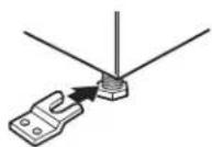
- Open dryer door all the way.
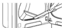
- Use flat head screw drive to open hinge latch.
natural_image
Line drawing of a hand using a screwdriver to adjust or install a mechanical component (no text or symbols present)- Pinch the hinge latch between two fingers and pull forward. Repeat on other side of dryer door.
natural_image
Technical line drawing of a mechanical clamp or tool with labeled point A (no text or symbols beyond label)A. Hinge latch
- Close the dryer door as far as it will shut.
- Lift the dryer door while holding both sides.
Continue to push the dryer door closed and pull it away from the dryer door frame.
natural_image
Illustration of a hand holding a door panel with two arrows indicating rotation (no text or symbols)To Replace:
- Insert both hanger arms into the front panel.
natural_image
Illustration of a hand using a tool to adjust or install a panel, with an inset showing the same component (no text or symbols present)- Open the dryer door. You should hear a "click" as the door is set into place.
- Move the hinge levers back to the locked position. Check that the door is free to open and close. If it is not, repeat the removal and installation procedures.
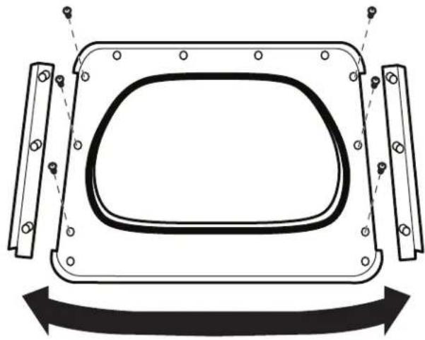
DOOR REVERSAL (ON SOME MODELS)
The following instructions are applicable for models with side opening door.
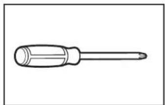
Tools Needed:
natural_image
Line drawing of a screwdriver with a flat head and threaded shaft (no text or symbols)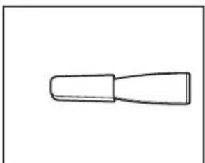
natural_image
Simple line drawing of a tool or grip (no text or symbols)Flat-blade screwdriver Plastic putty knife
natural_image
Line drawing of a screwdriver with a flat blade (no text or symbols)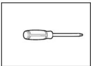
natural_image
Line drawing of a screwdriver with a flat head and threaded shaft (no text or symbols)Minimum 8" long TORX T20 ^+ screwdriver
2 Phillips screwdriver
You can change your door swing from a right-side opening to a left-side opening, if desired.
- Place a towel or soft cloth on top of dryer or work space to avoid damaging the surface.
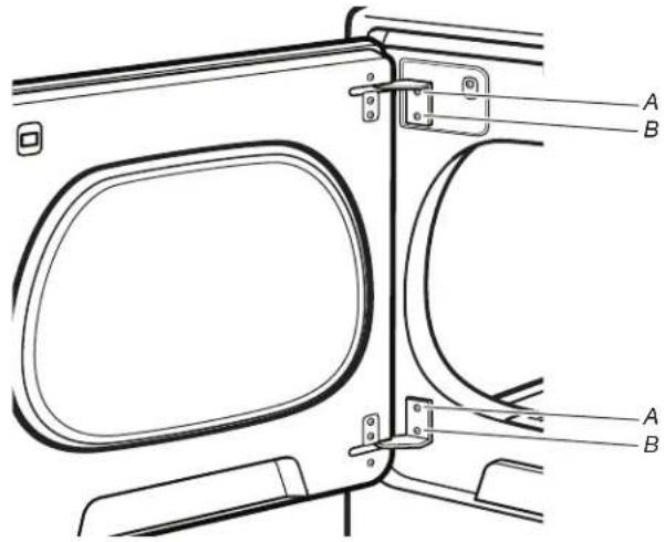
Remove door from dryer cabinet:
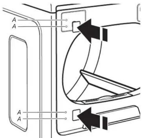
- Open the dryer door.
- Using a T20 screwdriver, remove screws (A) and then (B) screws from each of the two hinges that attach dryer door to front panel of dryer. Set the hinge screws off to the side for reinstalling the door.
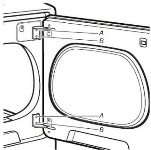
text_image
A B A B-
Remove the dryer door by lifting upward and out to lift the door off the cabinet. Lay the door on a flat, covered surface, with the inside of the door facing up.
-
Remove the 2 plastic plugs (A) located outside the dryer door opening.
text_image
A A A A- Install 2 plastic plugs (A) into screw holes where the hinges were removed in Step 4.
Reverse the strike:
- Remove the door strike (A) from the dryer door opening.
- Remove the cosmetic screw (B) (on some models) opposite the door strike (A).
text_image
A BA. Door strike
B. Cosmetic screw (on some models)
- Reinstall the door strike and cosmetic screw (on some models) on the opposite side of dryer door opening from where they were removed.
NOTE: Door strike and plugs must be on the same side of the dryer door opening.
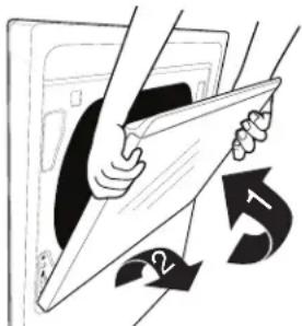
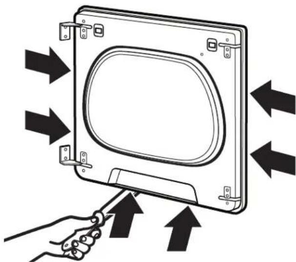
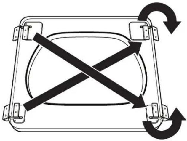
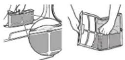
Remove the door assembly:
- Lay the door on a flat, covered surface with the inside of the door facing up. Remove the 3 plugs with a plastic putty knife. There is a cut out to stick the putty knife under to pop out.
natural_image
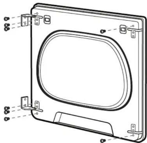
Diagram of a hand holding a tool interacting with a square frame containing an oval object, showing directional arrows (no text or symbols)- Remove the 8 screws from the dryer door and setscrews off to the side.
natural_image
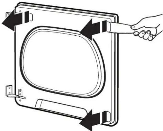
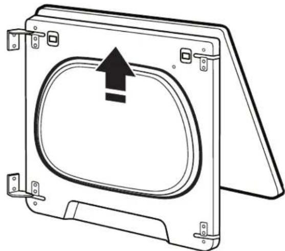
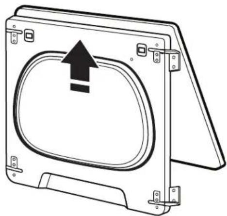
Technical line drawing of a door frame with mounting brackets and side connectors (no text or symbols)- Remove the inner door by using a plastic putty knife to separate the sides and bottom of the dryer door and trim. There are 2 snaps on left, right, and bottom of door. Insert the putty knife next to the snaps.
natural_image
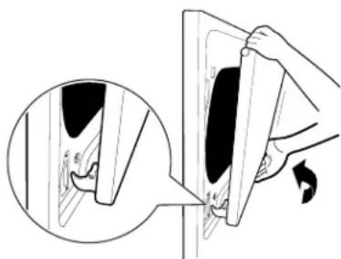
Diagram of a device with arrows indicating directional flow or movement, showing a hand holding a scroll-like object (no text or symbols present)- When you have the door separated from the frame, use a putty knife to lift up in the center tab and then pull door toward you and out.
natural_image
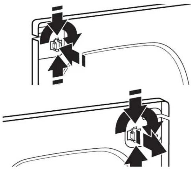
Technical line drawing of a mechanical component with an arrow indicating upward motion (no text or symbols)- Remove the door strike plug with a flathead screwdriver. Remove door strike by pinching the clips from the inside door panel and then rotate and push out the front. Insert door strike on the other side of dryer door by pushing in and then add the door strike plug.
natural_image
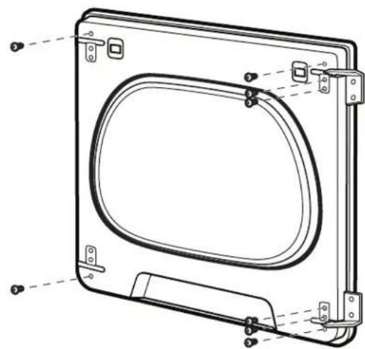
Pure diagram of two mechanical components with directional arrows indicating motion, no text or symbols present- Remove the door hinges and set off to the side.
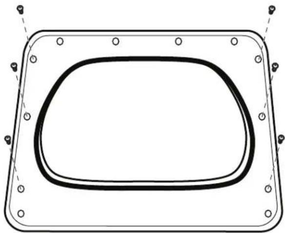
- Remove the 3 screws down the left and right sides of the door to remove the outer trim pieces.
natural_image
Technical line drawing of a rectangular frame with rounded corners and mounting holes (no text or symbols)- Lift door up and rotate trim pieces to the opposite side from which they were removed. Then screw trim pieces back in.
natural_image
Technical line drawing of a mechanical component with mounting flanges and a central oval cavity, shown with no text or symbols.- Add the hinges to the right side of the door and then flip the hinge labeled 1 to the bottom of the right side and the hinge labeled 2 to the top of the right side of the door.
natural_image
Diagram of a mechanical or electrical component with four arms and two curved arrows indicating rotation (no text or symbols)- Add inside door panel back into the dryer door by sliding the top into the top trim piece and then lower door down. Then press down on the corners to snap into place with the hinges lined up with the hinge holes.
natural_image
Technical line drawing of a mechanical component with an arrow indicating upward motion (no text or symbols)- Install 6 hinge screws and the other 2 screws.
natural_image
Technical line drawing of a door frame with mounting brackets and internal oval opening (no text or symbols)- Install hinge covers and plugs. Hinge covers will go in sideways to then rotate 90° and snap into place.
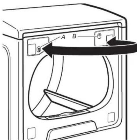
natural_image
Three-step diagram showing a door lock operation with arrows indicating clockwise motion (no text or symbols)- Hang door by placing set pin in dryer cabinet hole and slide door down. Using a T20 screwdriver, install (A) screws and then (B) screws. Tighten all hinge screws.
text_image
A B A BKeep dryer area clear and free from items that would block the airflow for proper dryer operation. This includes clearing piles of laundry in front of the dryer.
WARNING
Explosion Hazard
Keep flammable materials and vapors, such as gasoline, away from dryer.
Place dryer at least 18 inches (46 cm) above the floor for a garage installation.
Failure to do so can result in death, explosion, or fire.
CLEANING THE DRYER INTERIOR
To clean dryer drum
- Use a mild hand dish detergent mixed at a low concentration with very warm water, and rub with a soft cloth.
- Rinse well with a wet sponge or towel.
- Tumble a load of clean clothes or towels to dry drum OR
Use a microfiber cloth and hot water in a spray bottle to clean the drum and a second microfiber towel to dry.
NOTE: Garments that contain unstable dyes, such as denim blue jeans or brightly colored cotton items, may discolor the rear of the dryer interior. These stains are not harmful to your dryer and will not stain future loads of clothes. Dry unstable dye items inside out to avoid transfer of dye.
REMOVING ACCUMULATED LINT
From Inside the Dryer Cabinet
Lint should be removed every 2 years, or more often, depending on dryer usage. Cleaning should be done by a qualified appliance servicer or ventilation system cleaner.
From the Exhaust Vent
Lint should be removed every 2 years, or more often, depending on dryer usage.
CLEANING THE LINT SCREEN
Every load cleaning
The lint screen is located in the door opening of the dryer. A screen blocked by lint can increase drying time.
To clean:
Style 1
- Pull the lint screen straight up and out. Press tab down on front and open lint screen. Roll lint off the screen with your fingers. Do not rinse or wash screen to remove lint. Wet lint is hard to remove.
Style 2
- Pull the lint screen out of its holder. Roll lint off the screen with your fingers. Do not rinse or wash screen to remove lint. Wet lint is hard to remove.
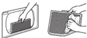
natural_image
Two illustrations showing hands cleaning a rectangular object with a lid (no text or symbols)- Push the lint screen firmly back into place.
IMPORTANT:
■ Do not run the dryer with the lint screen loose, damaged, blocked, or missing. Doing so can cause overheating and damage to both the dryer and fabrics.
If lint falls off the screen into the dryer during removal, check the exhaust hood and remove the lint. See "Venting Requirements" in the Installation Instructions.
■ Clean space where lint screen is located, as needed. Using a vacuum, gently remove any lint that has accumulated outside of the lint screen.
As-needed cleaning
Laundry detergent and fabric softener residue can build up on the lint screen. This buildup can cause longer drying times for your clothes, or cause the dryer to stop before your load is completely dry. The screen is probably clogged if lint falls off while the screen is in the dryer.
Clean the lint screen with a nylon brush every 6 months, or more frequently, if it becomes clogged due to a residue buildup.
To wash:
- Roll lint off the screen with your fingers.
- Wet both sides of lint screen with hot water.
- Wet a nylon brush with hot water and liquid detergent. Scrub lint screen with the brush to remove residue buildup.
Style 1 Style 2
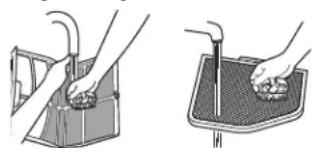
natural_image
Illustration of two hands using a tool to clean or wash a surface (no text or symbols present)- Rinse screen with hot water.
- Thoroughly dry lint screen with a clean towel. Reinstall screen in dryer.
CHANGING THE DRUM LIGHT (ON SOME MODELS)
- Unplug dryer or disconnect power.
- Open the dryer door. Locate the light bulb cover on the back wall of the dryer. Using a 1/4" (6 mm) nut driver or socket wrench, remove the screw located in the lower right-hand corner of the cover. Remove the cover.
natural_image
Line drawing of a hand using a screwdriver to switch an electrical socket (no text or symbols present)- Turn bulb counterclockwise. Replace the bulb with a 10 W appliance bulb only. Replace the cover and secure with the screw.
- Plug into a grounded outlet or reconnect power.
CHECK YOUR VENT SYSTEM FOR GOOD AIR FLOW
WARNING

Fire Hazard
Use a heavy metal vent.
Do not use a plastic vent.
Do not use a metal foil vent.
Failure to follow these instructions can result in death or fire.
GOOD AIR FLOW
Along with heat, dryers require good air flow to efficiently dry laundry. Proper venting will reduce your drying times and improve your energy savings. See Installation Instructions.
The venting system attached to the dryer plays a big role in good air flow. Blocked or crushed vents as well as improper venting installation will reduce air flow and dryer performance.
GOOD AIR FLOW (CONTD.)
Service calls caused by improper venting are not covered by the warranty and will be paid by the customer, regardless of who installed the dryer. To clean or repair venting, contact a venting specialist.
MAINTAIN GOOD AIR FLOW BY:
■ Cleaning your lint screen before each load.
■ Replace plastic or foil vent material with 4" (102 mm) diameter heavy, rigid vent material.
■ Use the shortest length of vent possible.
■ Use no more than four 90° elbows in a vent system; each bend and curve reduces air flow.
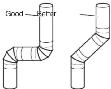
text_image
Good Better■ Remove lint and debris from the exhaust hood.
■ Remove lint from the entire length of the vent system at least every 2 years. When cleaning is complete, be sure to follow the Installation Instructions supplied with your dryer for final product check.
■ Clear away items from the front of the dryer.
NON-USE, STORAGE, AND MOVING CARE
Steam models only: Install and store your dryer where it will not freeze. Because some water may stay in the hose, freezing can damage your dryer. If storing or moving your dryer during freezing weather, winterize it.
Non-Use or Storage Care
If you will be on vacation or not using your dryer for an extended period of time, you should:
- Unplug dryer or disconnect power.
- Clean lint screen. See "Cleaning the Lint Screen."
- Turn off the water supply to the dryer. This helps to avoid unintended flooding (due to a water pressure surge) while you are away.
Moving Care
For power supply cord-connected dryers:
- Unplug the power supply cord.
- Gas models only: Close shut-off valve in gas supply line.
- Gas models only: Disconnect gas supply line pipe and remove fittings attached to dryer pipe.
- Gas models only: Cap the open fuel supply line.
- Steam models only: Shut off water faucet.
- Steam models only: Disconnect the water inlet hose from faucet, then drain the hose. Transport hose separately.
- Make sure leveling legs are secure in dryer base.
- Use tape to secure dryer door.
- On models with base trim: Remove base trim before moving dryer. See "Base trim".
WARNING

Electrical Shock Hazard
Disconnect power before servicing.
Replace all parts and panels before operating.
Failure to do so can result in death or electrical shock.
For direct-wired dryers:
- Disconnect power.
- Disconnect wiring from dryer and secure wire ends.
- Steam models only: Shut off water faucet.
- Steam models only: Disconnect the water inlet hose from faucet; then drain the hose. Transport hose separately.
- Make sure leveling legs are secure in dryer base.
- Use tape to secure dryer door.
- On models with base trim: Remove base trim before moving dryer. See "Base trim".
Reinstalling the Dryer
Follow the Installation Instructions to locate, level, and connect the dryer.
SPECIAL INSTRUCTIONS FOR STEAM MODELS
Water Inlet Hose
Replace inlet hose and hose screen after 5 years of use to reduce the risk of hose failure. Periodically inspect and replace inlet hose if bulges, kinks, cuts, wear, or leaks are found.
When replacing your inlet hose, record the date of replacement.
To Winterize the Dryer
- Unplug dryer or disconnect power.
- Shut off water faucet.
- Disconnect water inlet hose from faucet and drain.
To Use the Dryer Again
- Flush water pipes. Reconnect water inlet hose to faucet. Turn on water faucet.
- Plug in dryer or reconnect power as described in the Installation Instructions.
SÉCURITÉ DE LA SÉCHEUSE
natural_image
Line drawing of a screwdriver with a cylindrical head and threaded shaft (no text or symbols)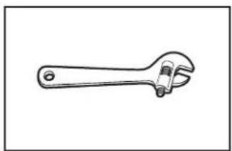
natural_image
Line drawing of an adjustable wrench (no text or symbols)natural_image
Simple line drawing of a rectangular object with three circular holes, no text or symbols present.natural_image
Two interlocked metal rings with clamps attached (no text or symbols)
natural_image
Simple line drawing of a tool or component with no text or symbolsnatural_image
Two line drawings of laboratory pipettes: a cylindrical tool and a micrometer (no text or labels)natural_image
Line drawing of a pair of pliers (no text or symbols)natural_image
Line drawing of a screwdriver with a flat shaft and end cap (no text or symbols)natural_image
Simple line drawing of a screwdriver (no text or symbols)natural_image
Line drawing of a pair of pliers (no text or symbols)natural_image
Simple line drawing of a tape measure (no text or symbols)natural_image
Line drawing of a pair of pliers (no text or symbols)natural_image
Line drawing of a adjustable wrench (no text or symbols)natural_image
Line drawing of an adjustable wrench (no text or symbols)natural_image
Simple line drawing of a jar with a lid (no text or symbols)natural_image
Illustration of three different types of threaded fasteners or bolts (no text or symbols present)natural_image
Technical line drawing of a mechanical component with labeled point A (no text or symbols beyond label)natural_image
Technical line drawing of a rectangular electronic component with internal cavity and mounting points (no text or symbols)natural_image
Illustration of three different types of threaded fasteners or bolts (no text or symbols present)natural_image
Technical diagram showing internal components of a device, including a connector and a display panel (no text or symbols present)natural_image
Diagram of a cable connector with wires and connectors, no text or symbols presentnatural_image
Simple line drawing of a wall socket with three pins (no text or symbols)natural_image
Simple line drawing of a three-pin electrical plug (no text or symbols)Prise à 4 broches
natural_image
Diagram of a multi-wire electrical cable with multiple leads (no text or symbols)natural_image
Line drawing of a multi-core cable with multiple leads (no text or symbols)Cosses rondes
text_image
Technical diagram of an electrical contactor with labeled components A, B, and Cnatural_image
Technical diagram of an electrical contactor or relay with multiple wires and connectors (no text or labels visible)natural_image
Simple line drawing of a wall socket with three leads (no text or symbols)natural_image
Simple line drawing of a push-button switch (no text or symbols)Prise à 3 broches

natural_image
Line drawing of a multi-core cable with multiple leads (no text or symbols)natural_image
Line drawing of a multi-core cable with multiple leads (no text or symbols)Cosses rondes
1. Retirer la vis centrale
natural_image
Technical diagram of an electrical component with labeled parts (no readable text or symbols)Retirer la vis de la borne centrale (B).
text_image
Technical diagram of an electrical switch or relay with labeled components A, B, and Cnatural_image
Pure electrical circuit lines without any symbolstext_image
Technical diagram of a mechanical assembly with labeled parts A, B, and Cnatural_image
Pure electrical circuit lines without any symbolstext_image
Technical diagram of an electrical component with labeled parts C, E, and Btext_image
Technical diagram of an electrical component with labeled parts A and F, showing wiring connections and mounting points.natural_image
Pure electrical circuit lines without any symbolsnatural_image
Technical diagram of an electrical connector with labeled parts (no readable text or symbols)Retirer la vis de la borne centrale (B).
text_image
Technical diagram of an electrical switch or relay with labeled components C and Bnatural_image
Pure electrical circuit lines without any symbolstext_image
Technical diagram of an electrical contactor with labeled components A, B, and Cnatural_image
Pure electrical circuit lines without any symbolsnatural_image
Simple line drawing of a vent or airflow device with a curved handle and rectangular panel (no text or symbols)Clapet à persiennes
natural_image
Simple line drawing of a 3D object resembling a folded paper or bracket (no text or symbols)natural_image
Simple line drawing of a folded paper or sheet with a diagonal line (no text or symbols)Type incliné
Coudes :
natural_image
Simple line drawing of a pipe with a circular component and a ring, no text or symbols present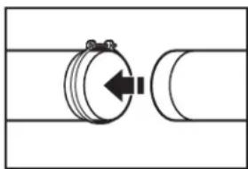
natural_image
Pure mechanical diagram showing a rotating component with a central arrow, no text or symbols presenttext_image
A B C D E F G B H IA. Sécheuse
B. Raccord coudé
C. Mur
D. Clapet
d'évacuation
E. Brides
natural_image
Line drawing of a portable air conditioner unit with attached piping (no text or symbols)natural_image
Technical line drawing of a curved structural component with hatched fill and a vertical guide bar (no text or symbols)natural_image
Pure diagram of two connected pipes with valve symbols, no text or labels presenttext_image
Diagram showing pipe connection with valve fittings and directional arrows indicating flow or movementnatural_image
Mechanical assembly diagram showing a hand operating a valve with hoses and a rotating arrow (no text or symbols)natural_image
Pure electrical circuit lines without any symbolsnatural_image
Illustration of a person using a cable to lift a car, showing motion direction (no text or symbols)natural_image
Pure diagram of a pipe fitting with valves and connectors, no text or symbols presentnatural_image
Three-panel illustration showing pipe fittings and water droplets during a procedure (no text or symbols)natural_image
Diagram of a mechanical piping system with a valve and pipe fitting (no text or labels)natural_image
Line drawing of a box with a door and lid, showing a left-pointing arrow (no text or symbols)text_image
Place level here Place level herenatural_image
Line drawing of a hand holding a wrench, with a tool inserted into a pipe (no text or symbols)text_image
Locating Pins Locking Featuresnatural_image
Illustration of two hands holding a rectangular object with a directional arrow indicating compression or force (no text or symbols)natural_image
Illustration of a hand using a screwdriver to adjust or install a mechanical component (no text or symbols visible)natural_image
Technical line drawing of a mechanical clamp or tool with labeled point A (no text or symbols beyond label)natural_image
Illustration of a hand holding a tablet with a circular arrow indicating rotation (no text or symbols)Remplacer :
natural_image
Illustration of a hand holding a device with a magnified inset showing a close-up of the interior (no text or symbols)natural_image
Line drawing of a screwdriver with a flat head and threaded shaft (no text or symbols)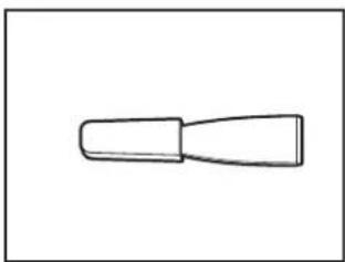
natural_image
Simple line drawing of a tool or grip (no text or symbols)natural_image
Line drawing of a screwdriver with a flat head and threaded shaft (no text or symbols)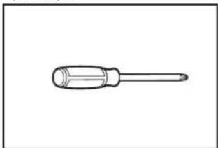
natural_image
Simple line drawing of a screwdriver (no text or symbols)Tournevis TORX T20 ^† de 8 po minimum.
natural_image
Diagram of a hand holding a tool interacting with a square frame containing an oval object, showing directional arrows (no text or symbols)natural_image
Technical line drawing of a door frame with mounting brackets and internal components (no text or symbols)natural_image
Diagram of a hand holding a device with arrows indicating airflow or movement (no text or symbols present)natural_image
Technical line drawing of a mechanical component with an arrow indicating upward motion (no text or symbols)natural_image
Pure diagram of two mechanical or electrical component diagrams without any text, numbers, or symbolsnatural_image
Technical line drawing of a rectangular frame with rounded corners and mounting holes (no text or symbols)natural_image
Technical line drawing of a mechanical component with mounting flanges and a central oval cavity, shown with no text or symbols.natural_image
Diagram of a mechanical or electrical component with four arms and directional arrows indicating rotation (no text or symbols)natural_image
Technical line drawing of a mechanical component with an arrow indicating upward motion (no text or symbols)natural_image
Technical line drawing of a door frame with mounting brackets and internal oval opening (no text or symbols)natural_image
Three-step diagram showing a door lock mechanism with curved lines and arrows indicating motion (no text or symbols)natural_image
Two illustrations showing hands holding a device inside a device casing, with no visible text or symbols.natural_image
Illustration of hands using a tool to clean or wash a surface (no text or symbols present)natural_image
Line drawing of a hand using a screwdriver to switch an open electrical socket (no text or symbols present)natural_image
Line drawing of a screwdriver with a cylindrical head and threaded shaft (no text or symbols)natural_image
Line drawing of an adjustable wrench (no text or symbols)natural_image
Simple line drawing of a rectangular object with three circular holes, no text or symbols present.natural_image
Two interlocked metal rings with clamps attached (no text or symbols)ventilación
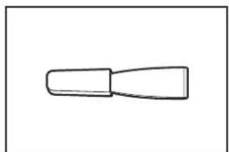
natural_image
Simple line drawing of a tool or component with a tapered handle (no text or symbols)natural_image
Two line drawings of laboratory pipettes: a cylindrical tool and a micrometer (no text or labels)natural_image
Line drawing of a pliers with metal fasteners (no text or symbols)natural_image
Line drawing of a screwdriver with a cylindrical head and end cap (no text or symbols)natural_image
Simple line drawing of a screwdriver (no text or symbols)natural_image
Line drawing of a pair of pliers (no text or symbols)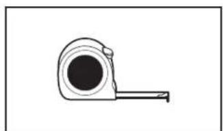
natural_image
Simple line drawing of a tape measure (no text or symbols)natural_image
Line drawing of a pair of pliers (no text or symbols)natural_image
Line drawing of a adjustable wrench (no text or symbols)natural_image
Line drawing of an adjustable wrench (no text or symbols)
natural_image
Simple line drawing of a jar with a lid (no text or symbols)natural_image
Illustration of three different types of threaded fasteners or bolts (no text or symbols present)text_image
Technical diagram of a mechanical assembly with labeled components A, B, C, D, and Enatural_image
Technical line drawing of a mechanical component with labeled point A (no text or symbols beyond label)natural_image
Technical line drawing of a rectangular electronic component with internal cavity and mounting base (no text or symbols)natural_image
Illustration of three threaded fasteners with hexagonal bases (no text or symbols)natural_image
Simple line drawing of a wall socket with four slots (no text or symbols)Tomacorriente de 4 hilos (tipo NEMA 14-30R)
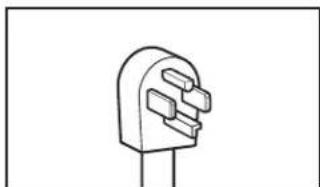
natural_image
Simple line drawing of a three-pin electrical plug (no text or symbols)Enchufe de 4 patas
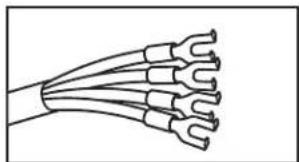
natural_image
Diagram of a multi-woven electrical cable with multiple terminal connectors (no text or symbols)natural_image
Diagram of a multi-core cable with multiple leads, no text or symbols presentTerminales de anillo
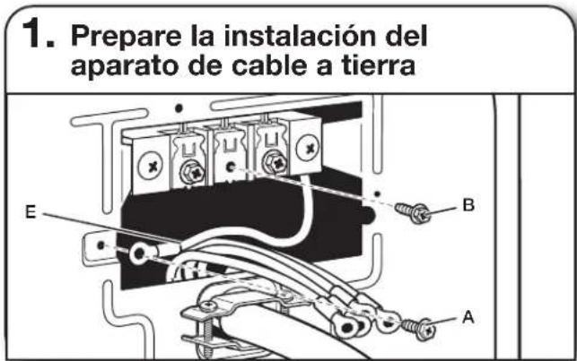
text_image
Technical diagram of an electrical contactor with labeled components A, B, and Cnatural_image
Technical diagram of an electrical contactor or relay with wiring and mounting brackets (no text or labels)natural_image
Simple line drawing of an electrical outlet with three leads (no text or symbols)Tomacorriente de 3 hilos (tipo NEMA 10-30R)
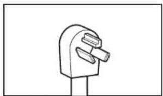
natural_image
Simple line drawing of a push-button socket (no text or symbols)Enchufe de 3 patas
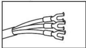
natural_image
Line drawing of a multi-core cable with multiple leads (no text or symbols)natural_image
Diagram of a multi-core cable with multiple leads (no text or symbols)Terminales de anillo
1. Quite el tornillo central
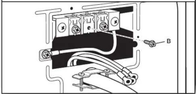
natural_image
Technical diagram of an electrical component with labeled connection points (no readable text or symbols)text_image
Technical diagram of an electrical component with labeled parts C and B, showing wiring connections and mounting points.natural_image
Pure electrical circuit lines without any symbolstext_image
Technical diagram of a mechanical or electrical component with labeled parts A, B, and Cnatural_image
Pure electrical circuit lines without any symbolstext_image
Technical diagram of an electrical component with labeled parts C, E, and Btext_image
Technical diagram of an electrical component with labeled parts A and F, showing wiring and connections.natural_image
Pure electrical circuit lines without any symbolstext_image
1" (25 mm) 3½" (89 mm)natural_image
Technical diagram of an electrical connector with wires and connectors (no text or symbols)text_image
Technical diagram of an electrical switch or relay with labeled components C and Bnatural_image
Pure electrical circuit lines without any symbolstext_image
Technical diagram of an electrical component with labeled parts C, E, and Bnatural_image
Pure electrical circuit lines without any symbolstext_image
4" (102 mm)natural_image
Simple line drawing of a vent or airflow device with a curved handle and rectangular panel (no text or symbols)Capota tipo persiana
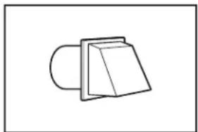
natural_image
Simple line drawing of a 3D object resembling a folded paper or bracket (no text or symbols)Capota tipo caja
Estilo aceptable:
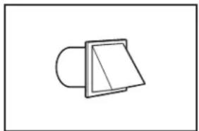
natural_image
Simple line drawing of a folded paper or plastic sheet with a diagonal line (no text or symbols)Capota angular
Codos:
natural_image
Simple line drawing of two circular objects connected by a double-headed arrow, no text or symbols present
natural_image
Pure mechanical diagram showing a rotating shaft and cylinder with an arrow indicating direction (no text or symbols)text_image
A B C D E F G B H Inatural_image
Simple line drawing of a 3D object with a box and a separate irregular shape, no text or symbols present.A B C
natural_image
Line drawing of a mechanical device with a cylindrical component and a side pipe fitting (no text or symbols)natural_image
Technical line drawing of a curved mechanical component with hatched fill and a vertical guide bar (no text or symbols)natural_image
Pure diagram of two pipe fittings with a valve, no text or symbols presenttext_image
Diagram showing pipe connection with valve parts and directional arrows indicating flow or movementnatural_image
Mechanical assembly diagram showing a hand operating a valve with hoses and a rotating arrow (no text or symbols)natural_image
Pure electrical circuit lines without any symbolsnatural_image
Illustration of a hand using a cable to lift a car, showing motion direction (no text or symbols)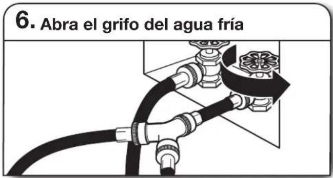
text_image
Place level here Place level herenatural_image
Line drawing of a hand holding a wrench, with a tool above a surface (no text or symbols)text_image
Locating Pins Locking Featuresnatural_image
Illustration of two hands holding a rectangular object with a curved arrow indicating rotation (no text or symbols)natural_image
Illustration of a hand using a tool to adjust or install a mechanical component (no text or symbols visible)natural_image
Technical line drawing of a mechanical clamp or tool with labeled component A (no text or symbols beyond label)A. Traba de bisagra
natural_image
Illustration of a hand holding a door panel with two arrows indicating rotation (no text or symbols)Para colocarla:
natural_image
Illustration of a hand using a tool to insert or install a component, showing a magnified view of the part (no text or symbols present)natural_image
Line drawing of a screwdriver with a flat head and threaded shaft (no text or symbols)natural_image
Simple line drawing of a tool or plunger (no text or symbols)natural_image
Line drawing of a screwdriver with a flat head and threaded shaft (no text or symbols)natural_image
Simple line drawing of a screwdriver (no text or symbols)Destornillador Phillips n.° 2