GMA3702 - AV receiver PIONEER - Free user manual and instructions
Find the device manual for free GMA3702 PIONEER in PDF.
| Product type | Two-channel bridgeable power amplifier |
| Brand | Pioneer |
| Model | GMA3702 |
| Output power (stereo) | 60 W × 2 (14.4 V, 4 Ω, 20 Hz – 20 kHz, ≤ 1% THD+N) |
| Output power (bridged) | 190 W × 1 (14.4 V, 4 Ω, 1 kHz, ≤ 1% THD+N) |
| Output power (2 Ω) | 95 W × 2 (14.4 V, 2 Ω, 1 kHz, ≤ 1% THD+N) |
| Supply voltage | 14.4 V DC (10.8 V to 15.1 V allowable) |
| Grounding | Negative terminal |
| Power consumption (continuous) | 14.5 A (4 Ω) |
| Average power consumption | 4 A (2 channels) / 6.5 A (1 channel) |
| Fuse | 25 A × 1 |
| Load impedance | 4 Ω (2 Ω to 8 Ω allowable) |
| Frequency response | 10 Hz to 70 kHz (+0 dB, -3 dB) |
| Signal-to-noise ratio | 95 dB (IHF-A network) |
| Total harmonic distortion | 0.05% (10 W, 1 kHz) |
| Low-pass filter (LPF) | Cutoff frequency: 40 Hz to 500 Hz, slope -12 dB/octave |
| Bass boost | Frequency: 50 Hz, levels: 0 dB / 6 dB / 12 dB |
| Gain control (RCA input) | 0.3 V to 6.5 V |
| Gain control (speaker input) | 3.0 V to 26 V |
| Maximum input level / impedance (RCA) | 6.5 V / 22 kΩ |
| Maximum input level / impedance (speaker) | 26 V / 16 kΩ |
| Protection functions | Short-circuit, overheating, and DC voltage protection |
| Care and cleaning | Wipe with a dry, soft cloth. Do not use chemicals. |
| Safety | Do not open the device. Use only the specified fuse. Disconnect the battery before installation. |
| Spare parts and repairability | Contact an authorized Pioneer dealer for after-sales service and spare parts. |
| General information | Vehicle audio amplifier, compatible with 12 V negative ground systems. |
Frequently Asked Questions - GMA3702 PIONEER
User questions about GMA3702 PIONEER
0 question about this device. Answer the ones you know or ask your own.
Ask a new question about this device
Download the instructions for your AV receiver in PDF format for free! Find your manual GMA3702 - PIONEER and take your electronic device back in hand. On this page are published all the documents necessary for the use of your device. GMA3702 by PIONEER.
USER MANUAL GMA3702 PIONEER
http://www.pioneerelectronics.com
http://www.pioneerelectronics.ca
PIONEERCORPORATION
28-8,Honkomagome2-chome,Bunkyo-ku,
Tokyo113-0021,JAPAN
PIONEERELECTRONICS(USA)INC.
P.O.Box1540,LongBeach,California90801-1540,U.S.A.
TEL:(800)421-1404
PIONEEREUROPENV
Haven1087,Keetberglaan1,B-9120Melsele,Belgium/Belgique
TEL:(0)3/570.05.11
PIONEERELECTRONICSASIACENTREPRETLED.
2JalanKilangBarat,#07-01,Singapore159346
TEL:65-6378-7888
PIONEERELECTRONICSAUSTRALIAPTY.LTD.
5ArcoLane,Heatherton,Victoria,3202Australia
TEL:(03)9586-6300
PIONEERELECTRONICSOCANADA,INC.
340FerrierStreet,Unit2,Markham,OntarioL3R2Z5,Canada
TEL:1-877-283-5901
TEL:905-479-4411
PIONEERELECTRONICSDEMEXICOS.A.deC.V.
Blvd.ManuelAvilaCamacho138,10piso
Col.LomasdeChapultepec,Mexico,D.F.11000
TEL:52-55-9178-4270
FAX:52-55-5202-3714
先锋股份有限公司
台北市內湖區瑞光路407號8樓
電話:886- (0) 2-2657-3588
先鋒電子(香港)有限公司
香港九龍長沙灣道909號5樓
電話:852-2848-6488
©2016PIONEERCORPORATION.
Allrightsreserved.
©2016PIONEERCORPORATION.
Tousdroitsdereproductionetde
ThankyouforpurchasingthisPIONEER product
Toensureproperuse,pleasereadthroughthis manualbeforeusingthisproduct.Itisespeciallyimportantthatyoureadandobserve
WARNING sand CAUTION sithismanual.
Please keep themualinasafeandaccessible placeforfuturereference.

ThisdevicecomplieswithPart15oftheFCC Rules. Operationissubjecttothefollowing twoconditions:
(1)Thisdevicemaynotcauseharmfulinterference,and(2)thisdevicemustacceptanyinterferencereceived,includinginterferencethat maycauseundesiredoperation.
InformationtoUser
Alterationnormodificationscarriedoutwithout appropriateauthorizationmayinvalidatethe user'srighttooperatethequipment.
Note
Thisequipmenthasbeentestedandfoundto complywiththelimitsforaClassBdigitaldevice, pursuanttoPart15oftheFCCRules.Theselimits aredesignedtoprovidereasonableprotection againstharmfulinterferenceinaresidential installation. Thisequipmentgenerates, uses and can radiateradiofrequencyenergyand, ifnot installed and used inaccordancewiththeinstructions, maycauseharmfulinterferencetoradio communications.However,thereisnoguarantee that interferencewillnotoccurinaparticular installation.Ifthisequipmentdoescauseharmful interferencetoradioortelevisionreception, whichcanbedeterminedbyturningthequipmentoffandon,theuserisencouragedotryto
correcttheinterferencebyoneormoreofthefollowingmeasures:
-Reorientorrelocatethereceivingantenna.
-Increasetheseparationbetweentheequipment andreceiver.
-Connecttthequipmentintoanoutletonacircuitdifferentfromthattowhichthereceiveris connected.
-Consultthedealeroranexperiencedradio/TV technicianforhelp.
After-saleservicefor Pioneerproducts
Pleasecontactthedealerordistributorfrom whereyoupurchasedthisunitforafter-sales service(includingwarrantyconditions)orany otherinformation.Incasethenecessaryinformationisnotavailable,pleasecontactthe companieslistedbelow:
Please donot ship your unit to the companies at the addresses listed below for repair without advance contact.
USA&CANADA
PioneerElectronics(USA)Inc.
CUSTOMERSUPPORTDIVISION
P.O.Box1760
LongBeach,CA90801-1760
800-421-1404
ForwarrantyinformationpleaseseetheLimitedWarrantysheetincludedwiththisunit.

Ifyouexperienceproblems
Shouldthisproductfailtooperateproperly, pleasecontactyourdealerornearestauthorizedPioneerServiceStation.
Beforeyoustart
Visitourwebsite
http://www.pioneerelectronics.com
inCanada
http://www.pioneerelectronics.ca
- Learnaboutproductupdates(suchasfirmwareupdates)foryourproduct.
- Registryyourproducttoreceive notices about product updates and safeguard purchases details in our files in the event of lossortheft.
- Accessowner'smanuals, spare parts information, service information, and much more.
TheSafetyofYourEarsisin YourHands
Getthemostoutofyourequipmentbyplaying itatasafelevel—alevelthatletsthesound comethroughclearlywithoutannoyingblaringordistortionand,mostimportantly,withoutfectingyoursensitivehearing.Sound canbedeceiving.Overtime,yourhearing "comfortlevel"adaptstohighervolumesof sound,sowhatsounds"normal"canactually beloudandharmfultoyourhearing.Guard againstthisbysettingyourequipmentata safelevelBEFOREyourhearingadapts.
ESTABLISHASAFELEVEL:
- Setyourvolumecontrollateralowsetting.
Slowly increasethesounduntilyoucan hearitcomfortablyandclearly,withoutdistortion. - Once you have established a comfortable soundlevel, set the dial and leave it there.
BESURETOOBSERVETHEFOLLOWING GUIDELINES:
-
Donotturnupthevolumesohighthatyou can'thearwhat'saroundyou.
Usecautionortemporarilydiscontinuuse inpotentiallyhazardoussituations. -
Donotuseheadphoneswhileoperatinga motorizedvehicle;theuseofheadphones maycreateatrafchazardandisillegal in manyareas.
Beforeconnecting/ installingtheamplifier

WARNING
Theuseofaspecialredbatteryandground wireRD-223,availableseparately,isrecommended.Connectthebatterywiredirectlyto thecarbatterypositiveterminal ④ andthe groundwiretothecarbody.
- This unit is for vehicles with 12V battery and negative grounding. Before installing in recreational vehicles, trucksorbuses, check the battery voltage.
- Wheninstallingthisunit, makesuretoconnectthegroundwirefirst. Ensures that the groundwire is properly connected to metal part of the car's body. The groundwire of the one of this unit must be connected to the car separately with different screws. If there are more sensors falling out, it could result in fire, generation of smoke or malfunction.
Alwaysuseafuseoftheratingprescribed. Theuseofanimproperfusecouldresultin overheatingandsmoke,damagetotheproductandjury,includingburns.
- Check the connection of the powersupply and speakers if the use of these separately sold batterywire or the amplifier fuses. Determine and resolve the cause, then replace the fuse with an identical equivalent.
Alwaysinstalltheamplifieronaflatsurface. Donotinstalltheamplifieronasurfacethat isnotflatoronasurfacewithaprotrusion. Doingsocouldresultinmalfunction.
Beforeyoustart
- Wheninstallingtheamplifier, donotallow partssuchasextrascrewstogetcaughtbetweentheamplifierandtheautomobile. Doingsocouldcausealfunction.
- Donotallowthisunittocomeintocontact withliquids. Electricalshockcouldresult. Also,damagetothisunit,smoke,andoverheatingcouldresultfromcontactwithliquids. Thesurfacesoftheamplifierandanyattached speakersmayalsoheatupandcauseminor burns.
- Intheeventofanyabnormality, the power supplytotheamplifieriscutofftoprevent equipmentmalfunction.lfthisoccurs, switch thesystempoweroffandcheckthepower supplyandspeakerconnections.Ifyouareunabletodeterminethecause, pleasecontact yourdealer.
- Always disconnect thenegative terminal of the battery before hand to avoid the risk of electric shock or short circuit during installation.
- Donotattempttodisassembleormodifythis unit.Doingsomayresultinfire,electric shockorothermalfunction.

CAUTION
- Alwayskeep the volume lowenoughto hear outside sounds.
- Extendeduseofthecarstereowhiletheengineisatrestoridlingmayexhaustthebattery.
This product is evaluated in moderate and tropical climate condition under the Audio, video and similare electronic apparatus-Safety requirements, IEC60065.
Theographicalsymbol placedonthe productmeansdirectcurrent.
Abouttheprotectionfunction
Thisproducthasprotectionfunction.Whenthis productdetectssomethingabnormal,thefollowingfunctionswilloperatetoprotecttheproduct andspeakeroutput.
Thepowerindicatorwillturnoffandthemplifierwillshutdowninthesituationsoutlinedbelow.
—Ifthespeakeroutputterminalandspeaker wireareshort-circuited.
—IfaDCvoltageisappliedtothespeaker outputterminal.
- The amplifier will reduce the power output if the temperature insidethem amplifier gets high. If the temperature gets too high, the power indicator will turn off, and the amplifier will shutdown.

Important(Serialnumber)
Theserialnumberislocatedonthebottomof thisunit.Foryourownsecurityandconvenience, besuretorecordthisnumberontheenclosed warrantycard.
Note
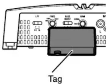
Beforeinstallingthisunitinyourvehicle,referto theillustrationbelowandremovethetag(GM-A5702only).
Donotusethepartsyouhavenooved(screws etc.)wheninstallingtheunitinyourvehicle.

Settingtheunit
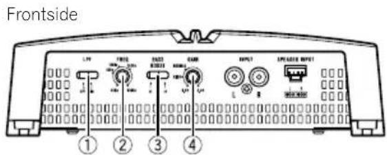
What'swhat
GM-A5702
GM-A3702
Toadjusttheswitch,useaflatheadscrewdri- verifneeded.
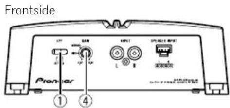
①LPF(low-passfilter)switch
Switchthesettingsbasedontheconnected speaker.
- Whenthe Subwoofer is connected: SelectON. This eliminates high range frequency and outputs low range frequency.
- Whenthefullrangespeakerisconnected: SelectOFF.OFFoutputstheentirefrequencyrange.
② FREQ(cutofffrequency)control
Cutofffrequencyselectablefrom40Hzto 500HziftheLPFselectswitchissettoON.
③ BASSBOOST(bassboostlevelcontrol) switch
You can select tabassboostlevel from 0dB, 6dB and 12dB.
④ GAIN(gain)control
Iftheoutputremainslow,evenwhenthecar stereovolumeisturnedup,turnthecontrolstoalowerlevel. Ifdistortionoccurs when thecarstereovolumeisturnedup, turnthesecontrolstoahigherlevel.
- ForusewithanRCAequippedcarstereo (standardoutputof500mV),settothe NORMALposition.ForcewithanRCA equippedPioneercarstereo,with maximum outputof4Vormore,adjustlevel to matchthatofthecarstereooutput.
- ForusewithanRCAequippedcarstereo withoutputof4V,settotheHIGHposition.
- Ifyouheartoomuchnoisewhenusing thespeakerinputterminals,turnthe gaincontroltoligherlevel.
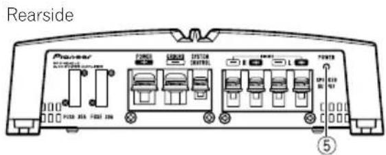
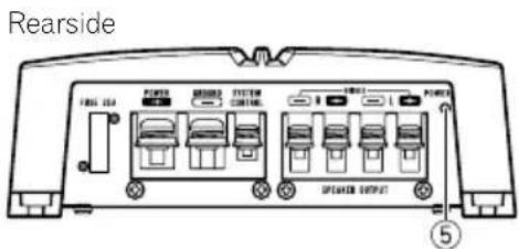
⑤Powerindicator
Thepowerindicatorlightsuptoindicate powerON.
Settingtheunit
Settinggainproperly
- Protectivefunctionincludedtoprevent malfunctionoftheunitand/orspeakers duetoexcessiveoutput,improperuseor improperconnection.
- When outputting high volumesoundetc., this function cutsofttheoutputforafew secondsasanormalfunction, but output is restored when the volume of the head unitisturned down.
- Acutinsoundoutputmayindicateimpro-persettingofthegaincontrol.Toensure continuousoundoutputwiththehead unitatahighvolume,setamplifiergain controtoalevelappropriateforthepreout maximumoutputleveloftheheadunit,so that volumecanremainunchangedandto controlexcessoutput.
- Despitecorrectvolumeandgainsettings, theunitsoundstillcutsoutperiodically. In suchcases, please contact the nearest authorized Pioneer Service Station.
Gaincontrolofthisunit
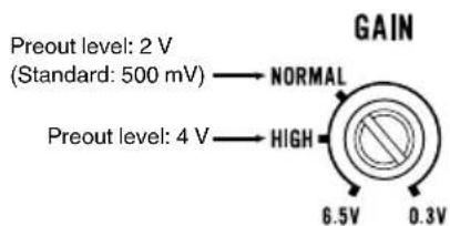
AboveillustrationsshowsNORMALgainsetting.
Relationshipbetweenamplifiergain andheadunitoutputpower
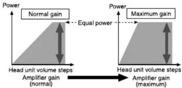
If amplifiergainisraisedimproperly,thiswill simply increasedistortion,withlittleincrease inpower.
Signalwaveformwhenoutputting at highvolumeusingamplifiergain control
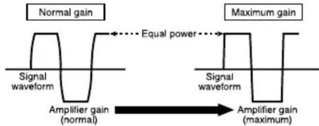
Ifthesignalwaveformisdistorteduetohigh output,eveniftheamplifiergainisraised,the outputpowerwillchangeonlyslightly.
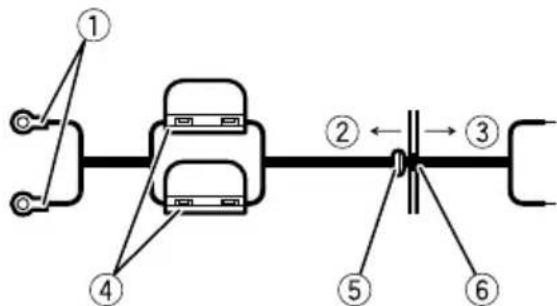
Connectingtheunits
Connectiondiagram
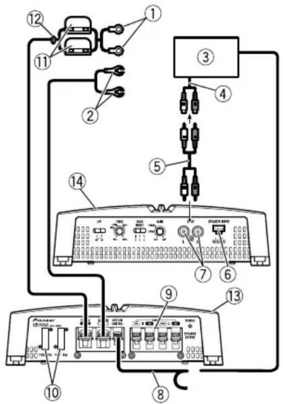
①Specialredbatterywire
RD-223(soldseparately)
Aftercompletingallotheramplifierconnections,finallyconnectthebatterywireterminal oftheamplifiertothepositive batteryterminal.
②Groundwire(Black)
RD-223(soldseparately)
Connecttometalbodyorchassis.
③ CarstereowithRCAoutputjacks(soldseparately)
(4)Externaloutput
⑤ConnectingwirewithRCApinplugs(soldseparately)
⑥Speakerinputterminal(useaconnectorincluded)
Pleaseseethefollowingsectionforspeaker connectioninstructions.RefertoConnections whenusingthespeakerinputwire.
⑦RCAinputjack
⑧Systemremotecontrolwire(soldseparately)
Connectmaleterminalofthiswiretothesystemremotecontrolterminalofthecarstereo. Thefemaleterminalcanbeconnectedtothe auto-antennarelaycontrolterminal.Ifthecar stereolacksystemremotecontrolterminal, connectthemaleterminaltothepowerterminaliaatheignitionswitch.
⑨ Speakeroutputterminals Pleaseseethefollowingsectionforspeaker connectioninstructions.RefertoConnecting thespeakers.
⑩Fuse30A×2(GM-A5702)/25A×1(GM-A3702)
1Fuse(30A)×2
⑫Grommet
③ Rearside
14Frontside
Connectingtheunits
Beforeconnectingthe amplifier

WARNING
- Securethewiringwithcableclampsoradhesivetape. Toprotectthewiring,wrapsections incontactwithmetalpartsinadhesivetape.
- Nevercuttheinsulationofthepowersupply tofeedpowertootherequipment.Current capacityoftthewireislimited.

CAUTION
- Nevershortenanywires, the protection circuit may malfunction.
- Neverwirethespeakernegativecabledirectly toground.
- Neverbandtogethermultiplespeaker'snegativecables.
- Ifthesystemremotecontrolwireoftheamplifierisconnectedtothepowerterminalviathe ignitionswitch(12VDC),theamplifierwillremainonwiththeignitionwhethertecar stereoisonoroff,whichmayexhaustbattery iftheengineisatrestoridling.
Installandroutetheseparatelysoldbattery wireasfaraspossiblefromthespeakerwires. Installandroutetheseparatelysoldbattery wire,groundwire,speakerwiresandthemplifiersfarawayaspossiblefromtheantenna,antennacableandtuner.
Aboutbridgedmode
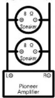
Diagram A - Proper
4ΩBridgedMode
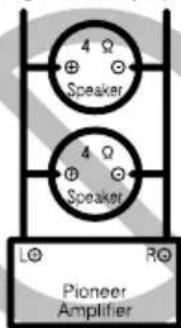
Diagram B - Improper
2Ω Bridged Mode
- Donotinstallorusethisamplifierbywiring speakersratedat4Ω(orlower)inparallelto achievea2Ω(orlower)bridgedmode(DiagramB).
Amplifierdamage,smoke,andoverheating couldresultfromimproperbridging.The amplifiersurfacecouldalsobecomehottoth touchandminorburnscouldresult.
Toproperlyinstalloruseabridgedmodeand achievea4Ωload,wiretwo8Ωspeakersin parallelwithLeft ④ andRight (DiagramA) oruseasingle4Ωspeaker.
Inaddition,refertothespeakerinstruction manualforinformationonthecorrectconnec tionprocedure. - Forany further enquiries,contact your local authorized Pioneer dealer or customer service.
Aboutsuitable specificationofspeaker
Ensurespeakersconformtothefollowing standards,otherwisethereisariskoffire, smokeordamage.Speakerimpedanceis2Ω to 8Ω for stereo connection, or 4Ω to 8Ω for monauralandotherbridgeconnection.
Connectingtheunits
Subwoofer
| SpeakerchannelPower | |
| Two-channeloutput | Nominalinput: Min.150W(GM-A5702) Min.60W(GM-A3702) |
| One-channeloutput | Nominalinput: Min.480W(GM-A5702) Min.190W(GM-A3702) |
Otherthansubwoofer
| SpeakerchannelPower | |
| Two-channeloutput | MAXinput: Min.300W(GM-A5702) Min.170W(GM-A3702) |
| One-channeloutput | MAXinput: Min.1000W(GM-A5702) Min.500W(GM-A3702) |

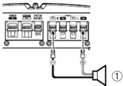
One-channeloutput
①Speaker(Mono)

Connectingthespeakers
Thespeakeroutputmodecanbetwo-channel (stereo)orone-channel(mono).Connectthe speakerleadstosuitthemodeaccordingo thefiguresshownbelow.
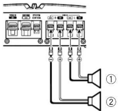
Two-channeloutput(Stereo)
①Speaker(Left)
②Speaker(Right)
Connectingtheunits
Connectionswhenusing thespeakerinputwire
Connect the car stereospeaker output wires to the amplifier using the supplied speaker input wire.
- DonotconnectboththeRCAinputandthespeakerinputatthesametime.
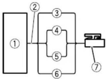
①CarStereo
②Speakeroutput
③White/black:Left
White:Left
⑤Gray/black:Right
⑥Gray:Right
⑦Speakerinputconnector
Tospeakerinputterminalofthisunit.
Note
Ifspeakerinputwiresfromheadunitareconnectedtothisamplifier, the amplifierwillautomaticallyturnonwhentheheadunitisturnedon. Whentheheadunitisturnedoff, the amplifier turnsoffautomatically.Thisfunctionmaynot workwithsomeheadunits.Insuchcases, make surethattheLeftchannelisconnectedcorrectly. If the function still doesnotwork, please use a systemremotecntrlwire(soldseparately). If multiple amplifiersaretobecomnectedtogether synchronously, connecttheheadunitandall amplifiersviathesystemremotecntrlwire.
Connectingthepowerterminal
Theusefaspecialredbatteryandground wireRD-223(soldseparately)isrecommended.Connectthebatterywiredirectlyto thecarbatterypositiveterminal ④ andthe groundwiretothecarbody.

WARNING
If the battery wire is not securely fixed to the terminal using the terminals screws, there is a risk of overheating, malfunction and injury, including minor burns.
1Routebatterywirefromenginecompartmenttothevehicleinterior.
- Whendrillingacablepass-holeintothevehiclebodyandroutingabatterywirethoroughit,takecarenttoshort-circuitthe wiredamagingitbythecutedgesorburrs ofthehole.
Aftercompletingallotheramplifierconnections,finallyconnectthebatterywireterminal oftheamplifiertothepositive batteryterminal.
①Positive+terminal
②Enginecompartment
③Vehicleinterior
④Fuse(30A)×2
⑤InserttheO-ringrubbergrommetintothe vehiclebody.
⑥Drilla14mm(1/2in.)holeintothevehicle body.
Connectingtheunits
2Twistthebatterywire,groundwire andsystemremotectrlwire.
3Attachlugstowireends.
Usepliers,etc.,tocrimplugstowires.
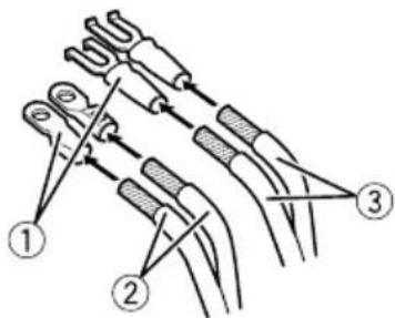
①Lug(soldseparately)
②Batterywire
③Groundwire
4Connectthewirestotheterminal. Fixthewiressecurelywiththeterminal screws.
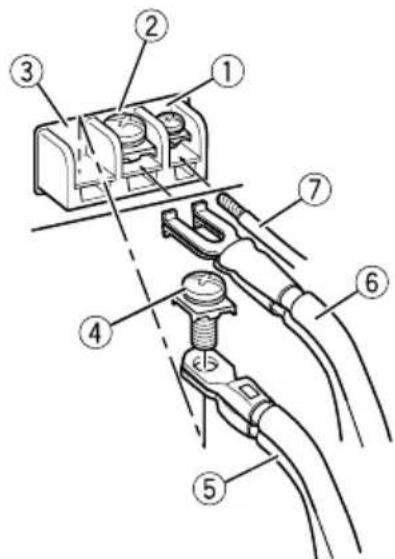
①Systemremotetocontrolterminal
②Groundterminal
③Powerterminal
④Terminalscrews
⑤Batterywire
⑥Groundwire
⑦Systemremotecontrolwire

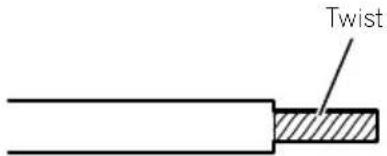
Connectingthespeaker outputterminals
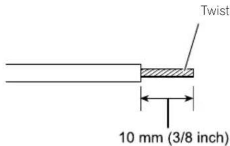
1Usewirecuttersorautilityknifeto stripteendofthespeakerwirestoexposeabout10mm(3/8in.)ofwire and thentwistthewire.
2Attachlugstowireends.
Usepliers,etc.,tocrimplugstowires.
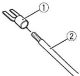
①Lug(soldseparately)
②Speakerwire
3Connectthespeakerwiresthespeakeroutputterminals.
Fixthespeakerwiressecurelywiththeterminalscrews.
ConnectingtheunitsInstallation
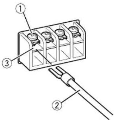
①Terminalscrews
②Speakerwires
③Speakeroutputterminals
Beforeinstallingtheamplifier
WARNING
Toensureproperinstallation,usethesupplied partsinthemannerspecified.Ifanyparts otherthanthosesuppliedareused,theymay damageinternalpartsoftheamplifier,orbecome loosecausingtheampliftiortoshut down.
- Donotinstallin:
—Placeswhereitcouldinjurethedriveror passengersifthevehiclestopssuddenly.
Placeswhereitmayinterferewiththedriver,suchasonthefloorinfrontofthedriver'sseat.
Installtappingscrewsinsuchawaythatthe screwtipdoesnn'touchanywire.Thisisimportanttopreventwiresfrombeingcutbyvibrationofthecar,whichcanresultinfire.
- Makesurethatwiresdonotgetcaughtinthe slidingmechanismoftheseseatsortouchthe legsofapersoninthevehicleassshort-circuit mayresult.
- Whendrillingtoinstalltheamplifier,always confirmnopartsarebehindthepaneland protectallcablesandimportantequipment (e.g.fuel/brakelines,wiring)fromdamage.
CAUTION
Toensureproperheatdissipationoftheamplifier,ensurethefollowingduringinstallation:Allowadequatespaceabovetheamplifier forproperventilation.
—Donotcovertheamplifierwithafloormat orcarpet.
Protectionfunctionmayactivatetoprotectthe amplifieragainstoverheatingduetoinstantioninlocationswheresufficentheatcannot bedissipated,continuoususeunderhigh-volumeconditions,etc.Insuchcases,theamplifierreducesthepoweroutputshuts downuntilithascooledtoacertaindesignatedtemperature.
- Placeallcablesawayfromhotplaces,such asneartheheateroutlet.
Installation
Theoptimalinstallationlocationdiffersdependingonthecarmodel.Securethempliferatasufficientlyrigidlocation.
- Checkallconnectionsandsystemsbefore finalinstallation.
Afterinstallingtheamplifier, confirmthat the spare tire, jackandtoolscanbeeasilyremoved.
Exampleofinstallationon thefloormatorchassis
1Placethemamplifierinthedesiredinstallationlocation.
Insertthesuppliedtappingscrews(4mm× 18mm(1/8in.×3/4in.))intothescrewholes andpushonthescrewswithascrewdriverso theymakeanimprintwheretheinstallation holesaretobelocated.
2Drill2.5mm(1/8in.)diameterholesat theirimprintseitheronthecarpetordirectly onthechassis.
3Installtheamplifierwiththeuseof suppliedtappingscrews(4mm×18mm (1/8in.×3/4in.).
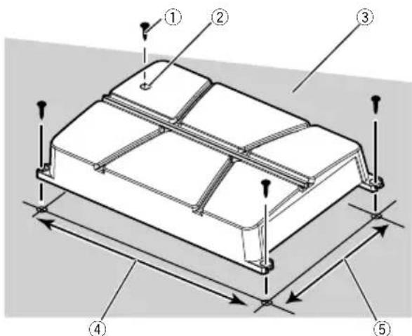
①Tapping screws(4mm×18mm(1/8in.× 3/4in.))
②Drilla2.5mm(1/8in.) diameterhole.
③Floormatorchassis
④Hole-to-holedistance:343mm(13-1/2in.) (GM-A5702)/233mm(9-1/8in.) (GM-A3702)
⑤Hole-to-holedistance:195mm(7-5/8 (GM-A5702)/160mm(6-1/4in.) (GM-A3702)
Additionalinformation
Specifications
GM-A5702
Powersource.14.4VDC(10.8Vto15.1V allowable)
Groundingsystem.Negativetype
Currentconsumption.36A(atcontinuouspower, 4Ω)
Averagecurrentconsumption 9.5 A (4 Ω for two channels) 15.5A(4Ωforonechannel)
Fuse. 30A×2
Dimensions(W×H×D)...356mm×60mm× 215mm (14in.x2-3/8in.x8-1/2in.)
Weight. 2.2kg(4.9lbs) (Leadsforwiringnotincluded)
Maximumpoweroutput.....300Wx2(4Ω)/500Wx2 (2Ω)/1000WTOTAL (BRIDGE)
Continuouspoweroutput...150W×2(at14.4V,4Ω, 20Hz to 20kHz, ≤1.0%THD +N)
480W×1(at14.4V,4Ω BRIDGE1kHz,≤1.0%THD +N) 240W×2(at14.4V,2Ω, 1kHz,≤1.0%THD+N)
Load impedance 4Ω (2Ω to 8Ω allowable)
Frequencyresponse.10Hzto70kHz(+0dB, -3dB)
Signal-to-noiseratio.96dB(IHF-Anetwork)
Distortion. 0.05% (10W,1kHz)
Lowpassfilter: Cutofffrequency.40Hzto500Hz Cutoffslope-12dB/oc
Bassboost: Frequency. .50Hz Level. 0dB/6dB/12dB
Gaincontrol: RCA. .0.3Vto6.5V Speaker. 3.0Vto26V
Maxuminputlevel/impedance: RCA. 6.5V/22kΩ Speaker. 26V/16kΩ
CEA2006Specifications

Poweroutput.150WRMSx2Channels (at14.4V,4Ωand≤1% THD+N)
S/N ratio. 75dBA(reference:1Winto 4Ω)
GM-A3702
Powersource.14.4VDC(10.8Vto15.1V allowable)
Groundingsystem.Negativetype
Currentconsumption.14.5A(atcontinuouspower, 4Ω)
Averagecurrentconsumption 4A(4Ωfor two channels) 6.5A(4Ωforonechannel)
Fuse. 25A×1
Dimensions(W×H×D)...246mm×60mm× 180mm (9-5/8in.×2-3/7-1/8in.)
Weight. 1.4kg(3.1Ibs) (Leadsforwiringnotincluded)
Maximumpoweroutput.....170Wx2(4Ω)/250Wx2 (2Ω)/500WTOTAL (BRIDGE)
Continuouspoweroutput...60W×2(at14.4V,4Ω, 20Hzto20kHz,≤1.0%THD +N) 190W×1(at14.4V,4Ω BRIDGE1kHz,≤1.0%THD +N) 95W×2(at14.4V,2Ω, 1kHz,≤1.0%THD+N)
Load impedance 4Ω (2Ω to 8Ω allowable)
Frequencyresponse.10Hzto70Hz(+0dB, -3dB)
Signal-to-noiseratio.95dB(IHF-Anetwork)
Distortion.0.05%10W,1kHz
Lowpassfilter: Cutofffrequency.80Hz Cutoffslope-12dB/oc
Gaincontrol:
RCA. 0.3Vto6.5V
Speaker. 3.0Vto26V
Additionalinformation
Maximuminputlevel/impedance:
RCA. 6.5V/22kΩ
Speaker. 26V/16kΩ
CEA2006Specifications

Poweroutput.60WRMSx2Channels(at
14.4V,4Ωand≤1%THD
+N)
S/Nratio. 78dBARefence:1Winto
4Ω)
Notes
- Specificationsandthedesignaresubjectto modificationswithoutnotice.
Theaveragecurrentconsumptionisnearly themaximumcurrentconsumptionbythis unitwhenanaudiosignalisinput.Usethis valuewhenworkingouttotalcurrentconsumptionbymultiplepoweramplifiers.
Avantdecommencer
http://www.pioneerelectronics.com
auCanada
http://www.pioneerelectronics.ca