
GMA6704 - AV receiver PIONEER - Free user manual and instructions
Find the device manual for free GMA6704 PIONEER in PDF.
| Product Type | Four-channel bridgeable power amplifier |
| Brand | PIONEER |
| Model | GM-A6704 |
| Dimensions (W × H × D) | 356 mm × 60 mm × 215 mm |
| Weight | 2.2 kg (wiring cables not included) |
| Supply voltage | 14.4 V DC (10.8 V to 15.1 V acceptable) |
| Maximum current consumption | 31 A (4 Ω continuous supply) |
| Average current consumption | 8.5 A (4 Ω, four channels) / 14 A (4 Ω, two channels) |
| Fuse | 25 A × 2 |
| Maximum output power | 170 W × 4 (4 Ω) / 250 W × 4 (2 Ω) / 1000 W total (bridged) |
| Continuous output power | 60 W × 4 (14.4 V, 4 Ω, 20 Hz–20 kHz, ≤1% THD+N); 190 W × 2 (14.4 V, 4 Ω bridged, 1 kHz, ≤1% THD+N); 95 W × 4 (14.4 V, 2 Ω, 1 kHz, ≤1% THD+N) |
| Load impedance | 4 Ω (2 Ω to 8 Ω acceptable) |
| Frequency response | 10 Hz to 70 Hz (+0 dB, -3 dB) |
| Signal-to-noise ratio | 95 dB (IEC-A network) |
| Distortion | 0.05% (10 W, 1 kHz) |
| Low-pass filter (Channel A) | Cutoff frequency 80 Hz |
| Maximum input level/ impedance (RCA) | 6.5 V / 22 kΩ |
| Maximum input level/ impedance (speaker) | 26 V / 16 kΩ |
| Main features | Bridgeable, adjustable high-pass/low-pass filters, gain control, bass boost (0/6/12 dB), 2CH/4CH input selector, protection against short circuits, overheating and DC voltage |
| Maintenance and cleaning | Clean the exterior with a dry cloth; avoid contact with liquids |
| Safety | Use special ground and battery wires; observe impedances; install on a flat, well-ventilated surface |
| Spare parts and repairability | Contact an authorized Pioneer service center; use fuses with the same specifications |
| General information | Amplifier for 12 V negative ground vehicles; automotive use |
Frequently Asked Questions - GMA6704 PIONEER
User questions about GMA6704 PIONEER
0 question about this device. Answer the ones you know or ask your own.
Ask a new question about this device
Download the instructions for your AV receiver in PDF format for free! Find your manual GMA6704 - PIONEER and take your electronic device back in hand. On this page are published all the documents necessary for the use of your device. GMA6704 by PIONEER.
USER MANUAL GMA6704 PIONEER
PIONEERELECTRONICSAUSTRALIAPTY.LTD.
5ArcoLane,Heatherton,Victoria,3202Australia TEL:(03)9586-6300
PIONEERELECTRONICSOCANADA,INC.
340FerrierStreet,Unit2,Markham,OntarioL3R2Z5,Canada
TEL:1-877-283-5901
TEL:905-479-4411
PIONEERELECTRONICSDEMEXICOS.A.deC.V.
Blvd.ManuelAvilaCamacho138,10piso
Col.LomasdeChapultepec,Mexico,D.F.11000
TEL:52-55-9178-4270
FAX:52-55-5202-3714
先锋股份有限公司
ThankyouforpurchasingthisPIONEER product
Toensureproperuse,pleasereadthroughthis manualbeforeusingthisproduct.Itisespeciallyimportantthatyoureadandobserve
WARNING sand CAUTION sithismanual.
Please keep themualinasafeandaccessible placeforfuturereference.

Ifyouwanttodisposethisproduct,donotmix itwithgeneralhouseholdwaste.Thereiseaseparatecollectionsystemforusedelectronic productsinaccordancedewithlegislationthatrequirespropertreatment,recoveryandrecyclc.
Privatehouseholdsinthememberstates of theEU,inSwitzerland and Norway may return theirusedelectronicproductsfreeofcharge todesignatedcollectionfacilitiesortoaretailer(ifyoupurchaseasimilarnewone).
For countriesnotmentionedabove,please contactyourlocalauthoritiesforthecorrect methodofdisposal.
Bydoingsoyouwillensurethatyourdispersed productundergoesthenecessarytreatment, recoveryandrecyclingandthuspreventpotentialnegativeeffectsontheenvironment
andhumanhealth.
Visitourwebsite
Visitusatthefollowingsite:
http://www.pioneer-car.co.uk
- Registryourproduct.Wewillkeepthedetailsofyourpurchasefiletohelpyou
refertothisinformationintheeventofan insuranceclaimsuchaslossorthoft.
Weofferthelatestinformationabout PIONEERCORPORATIONNonour website.
Ifyouexperienceproblems
Shouldthisproductfailtooperateproperly, pleasecontactyourdealerornearestauthorizedPioneerServiceStation.
Beforeconnecting/ installingtheamplifier

WARNING
Theuseofaspecialredbatteryandground wireRD-223,availableseparately,isrecommended.Connectthebatterywiredirectlyto thecarbatterypositiveterminal ④ andthe groundwiretothecarbody.
- This unit is for vehicles with a 12V battery and negative grounding. Before installing in recreational vehicles, trucks or buses, check the battery voltage.
- Wheninstallingthisunit,makesuretoconnectthegroundwirefirst.Ensurethatthe groundwireisproperlyconnectedtometal partsofthecar'sbody.Thegroundwireofthe oneofthisunitmustbeconnectedtothecar separatelywithdifferent screws.Ifthescrew forthegroundwireloosensorfallsout,it couldresultinfire,generationofsmokeormalfunction.
Alwaysuseafuseoftheratingprescribed. Theuseofanimproperfusecouldresultin overheatingandsmoke,damagetotheproductandjury,includingburns.
- Check the connection of the powersupply and speakers if the use of these separately sold batterywire or the amplifier fuses. Determine and resolve the cause, then replace the fuse with an identical equivalent.
- Alwaysinstalltheamplifieronaflatsurface. Donotinstalltheamplifieronasurfacethat isnotflatoronasurfacewithaprotrusion. Doingsocouldresultinmalfunction.
- Wheninstallingtheamplifier, donotallow partssuchasextrascrewstogetcaughtbetweenthemplifierandtheautomobile. Doingsocouldcausemalfunction.
- Donotallowthisunittocomeintocontact withliquids. Electricalshockcouldresult. Also,damagetothisunit,smoke,andover-heatingcouldresultfromcontactwithliquids. Thesurfacesoftheamplifierandanyattached
speakersmayalsoheatupandcauseminor burns.
- Intheeventofanyabnormality, the power supplytotheamplifieriscutofftoprevent equipmentmalfunction. Ifthisoccurs, switch thesystempoweroffandcheckthepower supplyandspeakerconnections.Ifyouareunabledeterminetherecause, pleasecontact yourdealer.
- Always disconnect thenegative terminal of the battery before handtoavoidtherisk of electricshockorshortcircuit during installation.
- Donotattemptodisassembleormodifythis unit.Doingsomayresultinfire,electric shockorothermalfunction.

CAUTION
- Alwayskeep the volume lowened to hear outside sounds.
- Extendeduseofthecarstereowhiletheengineisatrestoridlingmayexhaustthebattery.
This product is evaluated in moderate and tropical climate condition under the Audio, video and similare electronic apparatus-Safety requirements, IEC60065.
Theographicalsymbol placedonthe productmeansdirectcurrent.
Abouttheprotectionfunction
Thisproducthasprotectionfunction.Whenthis productdetectssomethingabnormal,thefollowingfunctionswilloperatetoprotecttheproduct andspeakeroutput.
Thepowerindicatorwillturnoffandthemplifierwillshutdowninthesituationsoutlined below.
—Ifthespeakeroutputterminalandspeaker wireareshort-circuited.
—IfaDCvoltageisappliedtothespeaker outputterminal.
BeforeyoustartSettingtheunit
Theamplifierwillreducethepoweroutputif thetemperatureinsidetheamplifiergets high.lfthetemperaturegetstoohigh,the powerindicatorwillturnoff,andthemplifier willshutdown.
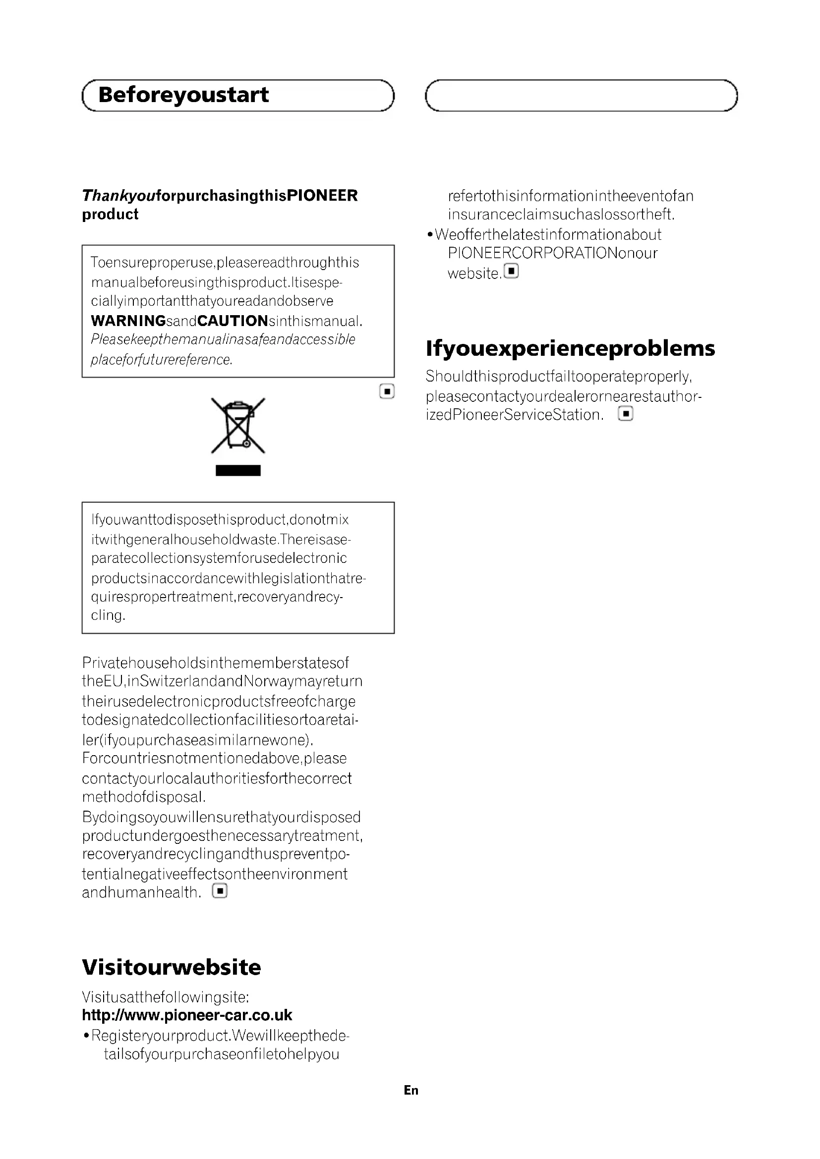
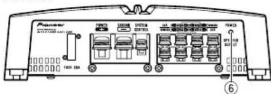
What'swhat
GM-A6704
Frontside
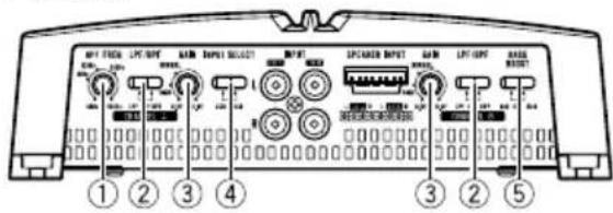
Rearside
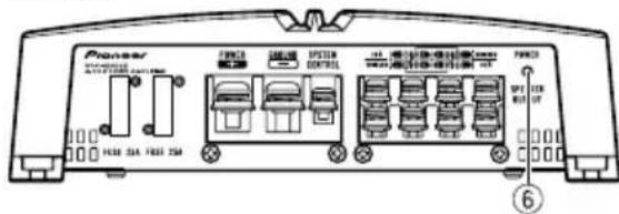
GM-A4704
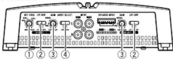
Frontside
Rearside
Toadjusttheswitch,useaflatheadscrewdri- verifneeded.
①HPFFREQ(cutofffrequency)control
Cutofffrequencyselectablefrom40Hzto 500 Hz if the HPF select switch is set to HPF.
- You can select cutoff frequency only for CHANNELA.
LPF(low-passfilter)/HPF(high-passfilter)selectswitch
Switchthesettingsbasedontheconnected speaker.
- Whenthe Subwooferisconnected:
Settingtheunit
SelectLPF.This eliminates highrange frequency and outputs low range frequency.
- Whenthefullrangespeakerisconnected: SelectHPForOFF.HPFeliminateslow rangefrequencyandoutputhighrange frequency.Offoutputstheentirefrequencyrange.
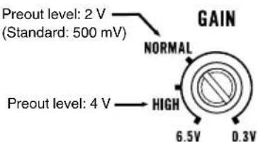
③ GAIN(gain)control
AdjustinggaincontrolsCHANNELA(channelA)andCHANNELB(channelB)helps alignthecarstereooutputtothePioneer amplifier.DefaultsettingistheNORMAL position. Iftheoutputremainslow,evenwhenthecar stereovolumeisturnedup,turnthecontrolstoalowerlevel.lfdistortionoccurs whenthecarstereovolumeisturnedup, turnthesecontrolstoahigherlevel.
-
Ifusingonlyoneinputplug,setthegain controlsforspeakeroutputsAandBto thesameposition.
-
ForusewithanRCAequippedcarstereo (standardoutputof500mV),settothe NORMALposition.ForcewithanRCA equippedPioneercarstereo,with maximum outputof4Vormore,adjustlevel to matchthatofthecarstereooutput.
-
ForusewithanRCAequippedcarstereo withoutputof4V,settotheHIGHposition.
④INPUTSELECT(inputselect)switch
Select2CHfortwo-channelinputand4CH forfour-channelinput.
- YoucanselectinputselectonlyforconnectionswhenusingtheRCAinputjack. Forconnectionswhenusingthespeaker inputwire,4CHwillbeusedautomaticallynomatterwhichswitchsettingis selected.
⑤ BASSBOOST(bassboostlevelcontrol) switch
You can select tabassboostlevelfrom0dB, 6dBand12dB.
- Bassboostlevelsettingappliesonlyto CHANNELB channelB)output.
6Powerindicator
Thepowerindicatorlightsuptoindicate powerON.
Settingtheunit
Settinggainproperly
- Protectivefunctionincludedtoprevent malfunctionoftheunitand/orspeakers duetoexcessiveoutput,improperuseor improperconnection.
- When outputting high volumesoundetc., this function cut off the output for a few seconds as anormalfunction, but output is restored when the volume of the head unitisturned down.
- Acutinsoundoutputmayindicateimpropersettingofthegaincontrol.Toensure continuousoundoutputwiththehead unitatahighvolume,setamplifergain controtoalevelappropriateforthepreout maximumoutputleveloftheheadunit,so that volumecanremainunchangedandto controllexcessoutput.
- Despitecorrectvolumeandgainsettings, theunitsoundstillcutsoutperiodically. In suchcases, please contact the nearest authorized Pioneer Service Station.
Gaincontrolofthisunit
AboveillustrationsshowsNORMALgainsetting.
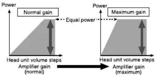
Relationshipbetweenamplifiergain andheadunitoutputpower
If amplifiergainisraisedimproperly, this will simply increase distortion, with little increase in power.
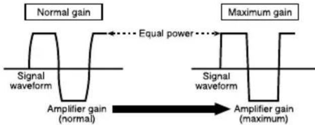
Signalwaveformwhenoutputting at highvolumeusingamplifiergain control
Ifthesignalwaveformisdistorteduetohigh output,eveniftheamplifiergainisraised,the outputpowerwillchangeonlyslightly.
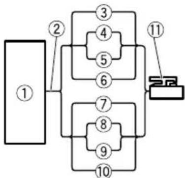
Connectingtheunits
Connectiondiagram
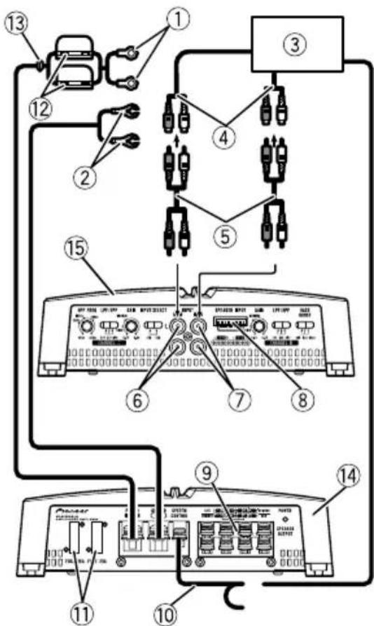
①Specialredbatterywire RD-223(soldseparately) Aftercompletingallotheramplifierconnections,finallyconnectthebatterywireterminal ofthemaplifiertothepositive batteryterminal.
②Groundwire(Black) RD-223(soldseparately) Connecttometalbodyorchassis.
③ CarstereowithRCAoutputjacks(soldseparately)
Externaloutput Ifonlyoneinputplugisused.donotconnect anythingtoRCAinputjackB.
⑤ConnectingwirewithRCApinplugs(soldseparately)
⑥RCAinputjackA
⑦RCAinputjackB
(8)Speakerinputterminal(useaconnectorincluded)
Pleaseseethefollowingsectionforspeaker connectioninstructions.RefertoConnections whenusingthespeakerinputwire.
⑨ Speakeroutputterminals Pleaseseethefollowingsectionforspeaker connectioninstructions.RefertoConnecting thespeakers.
10Systemremotecontrolwire(soldseparately) Connectmaleterminalofthiswiretothesystemremotecontrolterminalofthecarstereo. Thefemaleterminalcanbeconnectedtothe auto-antennarelaycontrolterminal.lfhecar stereolacksystemremotecontrolterminal, connectthemaleterminaltothepowerterminalviatheignitionswitch.
⑪Fuse25A×2(GM-A6704)/30A×1(GMA4704)
⑫Fuse(30A)×2
(13)Grommet
14Rearside
15Frontside
Note
INPUTSELECT(inputselect) switchmustbeset.
Fordetails,seeSettingtheunit.
Connectingtheunits
Beforeconnectingthe amplifier

WARNING
- Securethewiringwithcableclampsoradhesivetape. Toprotectthewiring,wrapsections incontactwithmetalpartsinadhesivetape.
- Nevercuttheinsulationofthepowersupply tofeedpowertootherequipment.Current capacityoftthewireislimited.

CAUTION
- Nevershortenanywires, the protection circuit may malfunction.
- Neverwirethespeakernegativecabledirectly toground.
- Neverbandtogethermultiplespeaker'snegativecables.
- Ifthesystemremotecontrolwireoftheamplifierisconnectedtothepowerterminalviathe ignitionswitch(12VDC),theamplifierwillremainonwiththeignitionwhethertecar stereoisonoroff,whichmayexhaustbattery iftheengineisatrestoridling.
Installandroutetheseparatelysoldbattery wireasfaraspossiblefromthespeakerwires. Installandroutetheseparatelysoldbattery wire,groundwire,speakerwiresandthemplifiersfarawayaspossiblefromtheantenna,antennacableandtuner.
Aboutbridgedmode
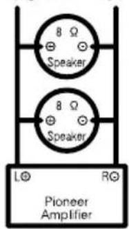
Diagram A - Proper
4ΩBridgedMode
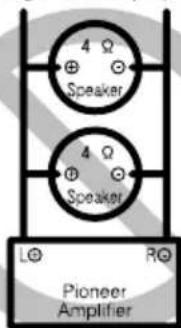
Diagram B - Improper
2Ω Bridged Mode
- Donotinstallorusethisamplifierbywiring speakersratedat4Ω(orlower)inparallelto achievea2Ω(orlower)bridgedmode(DiagramB).
Amplifierdamage,smoke,andoverheating couldresultfromimproperbridging.The amplifiersurfacecouldalsobecomehottothetouchandminorburnscouldresult.
Toproperlyinstalloruseabridgedmodeand achievea4Ωload,wiretwo8Ωspeakersin parallelwithLeft ① andRight DiagramA) oruseasingle4Ωspeaker.
Inaddition,refertothespeakerinstruction manualforinformationonthecorrectconnectionprocedure.
- Forany further enquiries,contact your local authorized Pioneer dealer or customer service.
Connectingtheunits
Aboutsuitable specificationofspeaker
Ensurespeakersconformtothefollowing standards,otherwisethereisariskoffire, smokeordamage.Speakerimpedanceis2Ω to 8 Ω or 4 Ω to 8 Ω for two-channel and other bridgeconnections.
Subwoofer
| SpeakerchannelPower | |
| Four-channeloutput | Nominalinput: Min.60W(GM-A6704) Min.40W(GM-A4704) |
| Two-channeloutput | Nominalinput: Min.190W(GM-A6704) Min.130W(GM-A4704) |
| Three-channelSpeakeroutputA | Nominalinput: Min.60W(GM-A6704) Min.40W(GM-A4704) |
| Three-channelSpeakeroutputB | Nominalinput: Min.190W(GM-A6704) Min.130W(GM-A4704) |
Otherthansubwoofer
| SpeakerchannelPower | |
| Four-channeloutput | Max-input: Min.170W(GM-A6704) Min.80W(GM-A4704) |
| Two-channeloutput | Max-input: Min.500W(GM-A6704) Min.260W(GM-A4704) |
| Three-channel SpeakeroutputA | Max-input: Min.170W(GM-A6704) Min.80W(GM-A4704) |
| Three-channel SpeakeroutputB | Max-input: Min.500W(GM-A6704) Min.260W(GM-A4704) |

Connectingthespeakers
Thespeakeroutputmodecanbefour-channel, three-channel(stereoandmono)ortwo-channel(stereoormono).Connectthespeaker leadsbasedonthemodeandthefigures shownbelow.
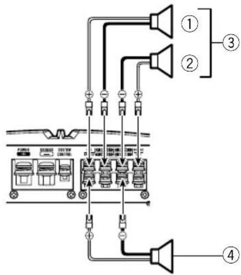
Four-channeloutput
①Right
②Left
③SpeakeroutA
④SpeakeroutB
Connectingtheunits
Three-channeloutput
①Right
②Left
③SpeakeroutA
④SpeakeroutB(Mono)
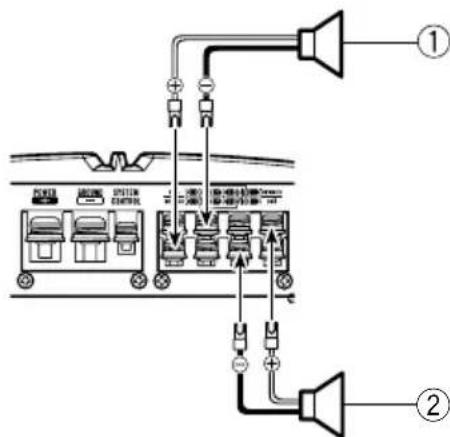
Two-channeloutput(Stereo)
①Speaker(Right)
②Speaker(Left)

Two-channeloutput(Mono)
①Speaker(Mono)

Connectionswhenusing theRCAinputjack
ConnectthecarstereoRCAoutputjackand theRCAinputjackoftheamplifier.
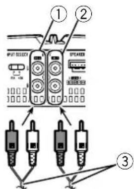
Four-channel/Three-channeloutput
- SlideINPUTSELECT(inputselect) switch to4CHposition.
(4)
①RCAinputjackA
②RCAinputjackB
③ConnectingwireswithRCAplugs(soldseparately)
④Fromcarstereo(RCAoutput)
Connectingtheunits
Ifonlyoneinputplugisused.e.g. when the carstereohasonlyoneoutput(RCAoutput), connecttheplugtoRCAinputjackArather thanB.
Two-channeloutput(Stereo)/(Mono)
- SlideINPUTSELECT(inputselect) switch to2CHposition.
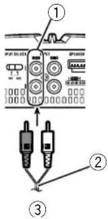
①RCAinputjackA
Fortwo-channeloutput,connecttheRCA plugstotheRCAinputjackA.
② Connecting wire with RCA pinplugs (sold separately)
③Fromcarstereo(RCAoutput)

Connectionswhenusing thespeakerinputwire
Connectthecarstereospeakeroutputwires totheamplifierusingthesuppliedspeaker inputwire.
- DonotconnectboththeRCAinputandthespeakerinputatthesametime.
①CarStereo
②Speakeroutput
White/black:CHA,Left
White:CHA,Left
⑤Gray/black:CHA,Right
⑥Gray:CHA,Right
⑦Green/black:CHB,Left
⑧Green:CHB,Left
⑨ Violet/black:CHB,Right
10Violet:CHB,Right
⑪Speakerinputconnector
Tospeakerinputterminalofthisunit.
Note
If speakerinputwiresfromheadunitareconnectedtothisamplifier, the amplifierwillautomaticallyturnonwhentheheadunitisturnedon. Whentheheadunitisturnedoff, the amplifier turnsoffautomatically.Thisfunctionmaynot workwithsomeheadunits.Insuchcases,make surethattheCHAftchannelisconnectedcorrectly.Ifthefunctionstilldoesnetwork, please useasystemremotectrlwire(soldseparately).Ifmultipleamplifiersaretobecounted togethersynchronously, connecttheheadunit andallamplifiersviathesystemremotectrl wire.
Connectingtheunits
Connectingthepowerterminal
Theusefaspecialredbatteryandground wireRD-223(soldseparately)isrecommended.Connectthebatterywiredirectlyto thecarbatterypositiveterminal ④ andthe groundwiretothecarbody.

WARNING
If the battery wire is not securely fixed to the terminal using the terminals screws, there is a risk of overheating, malfunction and injury, including minor burns.
1Routebatterywirefromenginecompartmenttothevehicleinterior.
- Whendrillingacablepass-holeintothevehiclebodyandroutingabatterywirethoroughit,takecarenttoshort-circuitthe wiredamagingitbythecutedgesorburrs ofthehole.
Aftercompletingallotheramplifierconnections,finallyconnectthebatterywireterminal oftheamplifiertothepositive batteryterminal.
①Positive terminal
②Enginecompartment
③Vehicleinterior
④Fuse(30A)×2
⑤InserttheO-ringrubbergrommetintothe vehiclebody.
⑥ Drilla14mmholeintothevehiclebody.
2Twistthebatterywire,groundwire andsystemremotecontrolwire.
3Attachlugstowireends.
Usepliers,etc.,tocrimplugstowires.
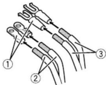
①Lug(soldseparately)
② Batterywire
③Groundwire
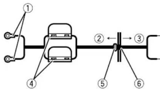
4Connectthewirestotheterminal.
Fixthewiressecurelywiththeterminal screws.
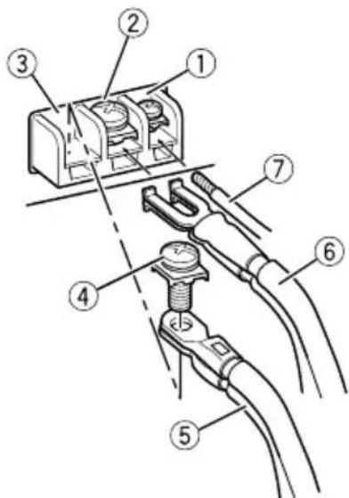
①Systemremotecontrolterminal
②Groundterminal
③Powerterminal
④Terminalscrews
⑤Batterywire
Connectingtheunits
⑥Groundwire
⑦Systemremotecontrolwire

Connectingthespeaker outputterminals
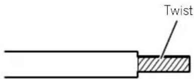
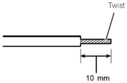
1Usewirecuttersorautilityknifeto stripteendofthespeakerwirestoexposeabout10mmofwireandthentwistthewire.
2Attachlugstowireends.
Usepliers,etc.,tocrimplugstowires.
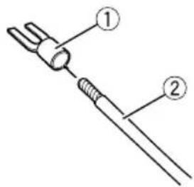
①Lug(soldseparately)
②Speakerwire
3Connectthespeakerwiresthespeakeroutputterminals.
Fixthespeakerwiressecurelywiththeterminalscrews.
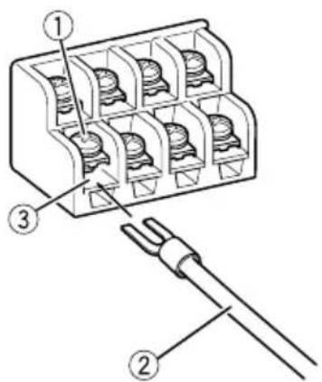
①Terminalscrews
②Speakerwires
③Speakeroutputterminals
Installation
Beforeinstallingtheamplifier

WARNING
Toensureproperinstallation,usethesupplied partsinthemannerspecified.Ifanyparts otherthanthesesuppliedareused,theymay damageinternalpartsoftheamplifier,orbecome loosecausingtheampliftertoshut down.
- Donotinstallin:
—Placeswhereitcould injurethedriveror passengersifthevehiclestopssuddenly.
—Placeswhereitmayinterferewiththedriver,suchasonthefloorinfrontofthedriver'sseat.
Installtappingscrewsinsuchawaythatthe screwtipdoesnn'touchanywire.Thisisimportanttopreventwiresfrombeingcutbyvibrationofthecar,whichcanresultinfire.
- Makesurethatwiresdonotgetcaughtinthe slidingmechanismoftheseseatsortouchthe legsofapersoninthevehicleassshort-circuit mayresult.
- Whendrillingtoinstalltheamplifier,always confirmnopartsarebehindthepaneland protectallcablesandimportantequipment (e.g.fuel/brakelines,wiring)fromdamage.

CAUTION
Toensureproperheatdissipationoftheamplifier,ensurethefollowingduringinstallation:Allowadequatespaceabovethemsplifierforproperventilation.Donotcoverthemplifierwithafloormat orcarpet.
- Protectionfunctionmayactivatetoprotectthe amplifieragainstoverheatingduetoinstantioninlocationswheresufficienttheatcannot bedissipated,continuoususeunderhigh-volumeconditions,etc.Insuchcases,theamplifierreducesthepoweroutputshuts downuntilithascooledtoacertaindesignatedtemperature.
- Placeallcablesawayfromhotplaces,such asneartheheateroutlet.
- Theoptimalinstallationlocationdiffersdependingonthecarmodel.Securethempliferatasufficientlyrigidlocation.
- Checkallconnectionsandsystemsbefore finalinstallation.
Afterinstallingtheamplifier, confirmthat the spare tire, jack and tools can beeasily removed.
Exampleofinstallationon thefloormatorchassis
1Placethemplifierinthedesiredinstallationlocation.
Insertthesuppliedtappingscrews(4mm× 18mm)intothescrewwholesandpushonthe screwswithascrewdriversotheymakeanimprintwhereetheinstallationholesaretobelocated.
2Drill2.5mm diameter holesattheim-printseitheronthecarpetordirectlyon the chassis.
3Installtheamplifierwiththeuseof suppliedtappingscrews(4mm×18mm).
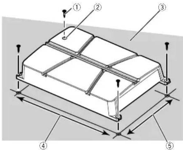
①Tapping-screws(4mm×18mm)
②Drill2.5mm diameterhole
③Floormatorchassis
④Hole-to-holedistance:343mm(GM-A6704)/313mm(GM-A4704)
⑤Hole-to-holedistance:195mm
Additionalinformation
Specifications
GM-A6704
Powersource.14.4VDC(10.8Vto15.1V allowable)
Groundingsystem.Negativetype
Currentconsumption.31A(atcontinuouspower, 4Ω)
Averagecurrentconsumption 8.5A(4Ωfor four channels) 14A(4Ωfortwochannels)
Fuse. 25Ax2
Dimensions(W×H×D)...356mm×60mm×215mm
Weight. 2.2kg(Leadsforwiringnot included)
Maximumpoweroutput.....170Wx4(4Ω)/250Wx4 (2Ω)/1000WTOTAL (BRIDGE)
Continuouspoweroutput...60W×4(at14.4V,4Ω, 20Hzto20kHz≤1%T +N)
190W×2(at14.4V,4Ω BRIDGE1kHz,≤1%THD +N) 95W×4(at14.4V,2Ω, 1kHz,≤1%THD+N)
Load impedance 4Ω (2Ω to 8Ω allowable)
Frequencyresponse.10Hzto70kHz(+0dB, -3dB)
Signal-to-noiseratio. 95dB(IEC-Anetwork)
Distortion.0.05%10W,1kHz
Lowpassfilter:
(Ach) Cutofffrequency.80Hz Cutoffslope-12dB/oc
(Bch) Cutofffrequency.80Hz Cutoffslope-12dB/oc
Highpassfilter:
(Ach) Cutofffrequency.40Hzto500Hz Cutoffslope-12dB/oc
(Bch) Cutofffrequency.80Hz Cutoffslope-12dB/oc
Bassboost: Frequency. .50Hz Level. 0dB/6dB/12dB
Gaincontrol: RCA. .0.3Mo6.5V Speaker. 3.0Mto26V
Maximuminputlevel/impedance: RCA. 6.5V/22kΩ Speaker. 26V/16kΩ
GM-A4704
Powersource.14.4VDC(10.8Vto15.1V allowable)
Groundingsystem.. Negativetype
Currentconsumption.20.5A(atcontinuouspower, 4Ω)
Averagecurrentconsumption 5.5A(4Ωfor four channels) 8.5A(4Ωfortwochannels)
Fuse. 30A×1
Dimensions(W×H×D)...326mm×60mm× 215mm Weight. .20kg(Leadsforwiringnot included)
Maximumpoweroutput.....80Wx4(4Ω)/130Wx4 (2Ω)/520WTOTAL (BRIDGE)
Continuouspoweroutput...40W×4(at14,4V,4Ω, 20Hzto20kHz≤1%THD
+N) 130W×2(at14.4V,4Ω BRIDGE1kHz,≤1%THD +N) 65W×4(at14.4V,2Ω, 1kHz,≤1%THD+N)
Load impedance 4Ω (2Ω to 8Ω allowable)
Frequencyresponse.10Hzto70Hz(+0dB, -3dB)
Signal-to-noiseratio.94dB(IEC-Anetwork) Distortion.0.05%(10W,1kHz)
Lowpassfilter:
(Ach) Cutofffrequency.80Hz Cutoffslope-12dB/oc
(Bch) Cutofffrequency.80Hz Cutoffslope-12dB/oc
Highpassfilter: (Ach) Cutofffrequency.40Hzto500Hz Cutoffslope-12dB/oc
(Bch) Cutofffrequency.80Hz Cutoffslope-12dB/oc
Gaincontrol:
RCA. 0.3Vto6.5V
Speaker. 3.0Vto26V
Maximuminputlevel/impedance: RCA. 6.5V/22kΩ Speaker. 26V/16kΩ
Notes
- Specificationsandthedesignaresubjectto modificationswithoutnotice.
Theaveragecurrentconsumptionisnearly themaximumcurrentconsumptionbythis unitwhenanaudiosignalinput.Usethis valuewhenworkingouttotalcurrentconsumptionbymultiplepoweramplifiers.
Avantdecommencer
Pentedecoupure.....12dB/octave
(CanalB)
Frequencedecoupure 80Hz
Pentedecoupure.....12dB/octave
Filtrepasse-haut:
(CanalA)
Frequencedecoupure 40Hzà500Hz
Pentedecoupure.....12dB/octave
(CanalB)
Frequencedecoupure 80Hz
Pentedecoupure.....12dB/octave
Accentuationdesgraves:
Fréquence. 50Hz
Niveau. 0dB/6dB/12dB
Commandedegain:
RCA. 0,3V6,5V
Pentedecoupure.....12dB/octave
(CanalB)
Frequencedecoupure 80Hz
Pentedecoupure.....-12dB/octave
Filtrepasse-haut:
(CanalA)
Fréquencedecoupure
40Hzà500Hz
Pentedecoupure.....-12dB/octave
(CanalB)
Fréquencedecoupure
80Hz
Pentedecoupure.....-12dB/octave
Commandedegain:
RCA. 0,3V6,5V


- PIONEERELECTRONICSAUSTRALIAPTY.LTD.
- PIONEERELECTRONICSOCANADA,INC.
- PIONEERELECTRONICSDEMEXICOS.A.deC.V.
- 先锋股份有限公司
- ThankyouforpurchasingthisPIONEER product
- Visitourwebsite
- Ifyouexperienceproblems
- Beforeconnecting/ installingtheamplifier
- WARNING
- CAUTION
- Abouttheprotectionfunction
- BeforeyoustartSettingtheunit
- What'swhat
- Settingtheunit
- ③ GAIN(gain)control
- ④INPUTSELECT(inputselect)switch
- ⑤ BASSBOOST(bassboostlevelcontrol) switch
- 6Powerindicator
- Settinggainproperly
- Connectingtheunits
- Connectiondiagram
- Note
- Beforeconnectingthe amplifier
- Aboutbridgedmode
- Aboutsuitable specificationofspeaker
- Connectingthespeakers
- Connectionswhenusing theRCAinputjack
- Four-channel/Three-channeloutput
- Two-channeloutput(Stereo)/(Mono)
- Connectionswhenusing thespeakerinputwire
- Connectingthepowerterminal
- 1Routebatterywirefromenginecompartmenttothevehicleinterior.
- 2Twistthebatterywire,groundwire andsystemremotecontrolwire.
- 3Attachlugstowireends.
- 4Connectthewirestotheterminal.
- Connectingthespeaker outputterminals
- 2Attachlugstowireends.
- 3Connectthespeakerwiresthespeakeroutputterminals.
- Installation
- Beforeinstallingtheamplifier
- Exampleofinstallationon thefloormatorchassis
- 1Placethemplifierinthedesiredinstallationlocation.
- 2Drill2.5mm diameter holesattheim-printseitheronthecarpetordirectlyon the chassis.
- Additionalinformation
- Specifications
- GM-A6704
- GM-A4704
- Notes
- Avantdecommencer
Brand : PIONEER
Model : GMA6704
Category : AV receiver