AKGD3050SS - Cooker AMANA - Free user manual and instructions
Find the device manual for free AKGD3050SS AMANA in PDF.

User questions about AKGD3050SS AMANA
0 question about this device. Answer the ones you know or ask your own.
Ask a new question about this device
Download the instructions for your Cooker in PDF format for free! Find your manual AKGD3050SS - AMANA and take your electronic device back in hand. On this page are published all the documents necessary for the use of your device. AKGD3050SS by AMANA.
USER MANUAL AKGD3050SS AMANA
- Additional alphanumeric characters representing other models in series may follow each model number.
(Natural Gas Only)
Please Read Manual Before Operating Cooktop
Installer
Leave this manual and other literature with consumer for future use.
Customer
Keep these instructions for future reference. If ownership changes, manual must accompany cooktop.
English 1
Francais 23
Contents 2
Model Identification 2
Parts and Accessories. 2
Service 2
Asure™ Extended Service Plan. 2
Important Safety Information 3
All Appliances 3
Surface Cooking Units 3
Delayed Ignition 4
Ventilation hoods. 4
In Case of Fire 4
Precautions 4
Installation. 4
Unpacking Cooktop 4
Countertop Cutout and Clearances 4
Minimum Requirements Below Cooktop 6
Duct Locations 6
Vent Locations for Downdraft Cooktop above
Undercounter Wall Oven 7
Duct Connections 8
Duct Length. 9
Duct Length Piece Equivalents 9
Gas and Electrical Entry Points 10
Gas and Electrical Installation Requirements 10
Gas Supply Location 11
Junction Box Location. 11
Gas Supply Pressure 12
Gas Connection 12
Testing for Gas Leaks 13
Cartridges. 14
Cooktop Features. 14
Installing Cartridges 14
Removing Cartridges 16
Adjusting Surface Burner Low Flame Size 16
Adjusting Burner Flame Characteristics. 17
Igniting Surface Burner without Electricity 17
Operation 18
Burner Cartridges 18
Smoke Control GrillTM 19
Griddle 19
Exhaust Fan 20
Care and Cleaning 20
Removing Control Panel and Gasket. 20
Cleaning 21
Warranty. 22
Model Identification
Complete enclosed registration card and promptly return. If registration card is missing, call Consumer Affairs Department at 1-800-843-0304 inside U.S.A. 319-622-5511 outside U.S.A. When contacting Amana, provide product information. Find product information on rating label located on bottom of cooktop. Record the following:
Model Number:
Manufacturing Number:
Serial or S/N Number:
Date of purchase:
Dealer's name and address:
Parts and Accessories
Purchase replacement parts and additional accessories (e.g. refrigerator shelves, dryer racks, or cooktop cartridges) over the phone. To order accessories for your Amana product, call 1-800-843-0304 inside U.S.A. or 319-622-5511 outside U.S.A.
Service
Keep a copy of sales receipt for future reference or in case warranty service is required. Any questions or to locate an authorized servicer, call 1-800-NAT-LSVC (1-800-628-5782) inside U.S.A. 319-622-5511 outside U.S.A. Warranty service must be performed by an authorized servicer. Amana also recommends contacting an authorized servicer if service is required after warranty expires.
Before Calling for Service
Review Owner's Manual before calling for service. If problems are not caused by defective workmanship or materials, or if part is customer replaceable, you could be charged for a service call though product is under warranty.
-
If you hear gas hissing but burner does not click, check electrical supply.
-
If burner flame is large and yellow, See, "Adjusting Surface Burner Flame Characteristics" section.
-
If burner flame is weak or noisy, see "Adjusting Burner Flame" section of manual.
Asure™ Extended Service Plan
Amana offers long-term service protection for this new cooktop. Asure™ Extended Service Plan is specially designed to supplement Amana's strong warranty. This plan covers parts, labor, and travel charges.
Call 1-800-528-2682 for information.

WARNING
This gas appliance contains or produces a chemical or chemicals which can cause death or serious illness and which are known to the state of California to cause cancer, birth defects or other reproductive harm. To reduce the risk from substances in the fuel or from fuel combustion make sure this appliance is installed, operated, and maintained according to the instructions in this booklet.

WARNING
To avoid risk of electrical shock, personal injury, or death, make sure your cooktop has been properly grounded and always disconnect from main power supply before any servicing.

WARNING
To avoid death, personal injury or property damage, information in this manual must be followed exactly.
Do not store or use gasoline or other flammable vapors and liquids in the vicinity of this or any other appliance.
WHAT TO DO IF YOU SMELL GAS
- Do not try to light any appliance.
- Do not touch any electrical switch; do not use any phone in your building.
- Immediately call your gas supplier from a neighbor's phone. Follow the gas supplier's instructions.
- If you cannot reach your gas supplier, call the fire department.
Installation and service must be performed by a qualified installer, service agency or the gas supplier.

CAUTION
Do not obstruct the flow of combustion or ventilation air.
All Appliances
- Proper Installation. Be sure your appliance is properly installed and grounded by a qualified technician.
- Never Use Your Appliance for Warming or Heating the Room.
- Do Not Leave Children Alone. Children should not be alone or unattended in the area where the appliance is in use. They should never be allowed to sit or stand on any part of the appliance.
- Wear Appropriate Apparel. Loose fitting or hanging garments should never be worn while using appliance.
- User Servicing. Do not repair or replace any part of the appliance unless specifically recommended in the manual. All other servicing should be referred to a qualified technician.
- Storage in or on Appliance. Flammable materials should not be stored on surface units.
- Do Not Use Water on Grease Fires. Smother fire or flame, or use dry chemical or foam-type extinguisher.
- Use Only Dry Potholders. Moist or damp potholders on hot surfaces may result in burns from steam. Do not let potholder touch elements. Do not use a towel or other bulky cloth.
Surface Cooking Units
- Use Proper Pan Size. This appliance is equipped with one or more surface units of different size. Select utensils having flat bottoms large enough to cover the surface burner. The use of undersized utensils will expose a portion of the flame to direct contact and may result in ignition of clothing. Proper relationship of utensil to burner will also improve efficiency.
- Never Leave Surface Units Unattended. Boilover causes smoking and greasy spillovers that may ignite.
- Protective Liners. Do not use aluminum foil to line drip bowls. Improper installation of these liners may result in a risk of electrical shock, or fire.
- Glazed Cooking Utensils. Only certain types of glass, ceramic, earthware, or other glazed utensils are suitable for cooktop service without breaking due to sudden change in temperature.
- Utensil Handles Should be Turned Inward and Not Extend Over Adjacent Surface Units. Reduce the risk of burns, ignition of flammable materials, and spillage due to unintentional contact with the utensil. Position utensil handle so that it is turned inward, and does not extend over adjacent surface units.
Delayed Ignition
Surface Burners
Burner should ignite within 4 seconds. If burner does not ignite within 4 seconds turn control knob to OFF position and follow directions in "Placing Grates and Burner Caps" and "Before Calling for Service" section. Try burner again. If burner still does not ignite in 4 seconds, contact an authorized servicer.
VENTILATION HOODS
- Clean Vents Frequently. Grease should not be allowed to accumulate on vent or filter.
- When flaming foods, turn fan on.
IN CASE OF FIRE
Fires can occur as a result of overcooking or excessive grease. Though a fire is unlikely, if one occurs, proceed as follows:
Surface Burner Fire
- Smother the fire with a nonflammable lid or baking soda, or use a Class ABC or BC extinguisher. Not water. Not salt. Not flour.
- As soon as it is safe to do so, turn the surface controls to OFF.
PRECAUTIONS
- Do not mix household cleaning products. Chemical mixtures may interact with objectionable or even hazardous results.
- Do not put plastic items on warm cooking areas. They may stick and melt.
- Do not allow pots to boil dry as this can cause damage to cooking surface and pan.
- Do not use cooktop surface as a cutting board.
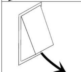
Unpacking Cooktop
- Remove all packing and printed material packed with cooktop.
- Slide cooktop out of box.
- To avoid damage, do not slide cooktop across countertop.
- Remove burner grates, burner caps, grill, vent cover, and pressure regulator from packing material.
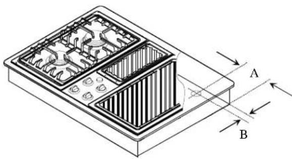
Countertop Cutout and Clearances
Prepare countertop opening according to dimensions shown in diagrams.

WARNING
To avoid serious burns or other personal injury caused by reaching over heated surface element, avoid locating storage cabinets above surface elements.

WARNING
To avoid serious burns or other personal injury, do not store items of interest to children above or behind cooktop. Children climbing on cooktop to reach items could be seriously injured.
IMPORTANT
To avoid property damage or personal injury, observe the following specifications.
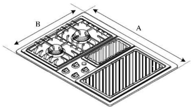
A-29½ inches
B-21½ inches
Cooktop Dimensions
Cabinet Requirements
Single cabinet installation requires a 36-inch width base cabinet.
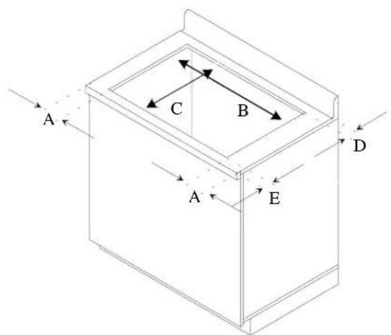
A-6/8 inches minimum
B-287/8 inches
C-20 5/8 inches
D-2½ inches minimum
E-17/s inches minimum
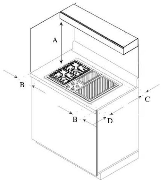
A-30 inches between cooking surface and unprotected wood or metal cabinet above cooktop. 24 inches between cooking surface and protected wood or metal cabinet above cooktop. Cabinet bottom must be protected by at least 14 inch thick millboard with not less than No. 28 MSG sheet steel, .015 inch thick stainless steel, .024 inch thick aluminum, or .020 inch thick copper.
B-5/8 inches minimum
C—2 inches minimum
D—1½ inches minimum
Minimum Clearances to Combustible Material
Countertop Cutout
Minimum Requirements Below Cooktop
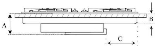
A-7½ inches
B-4 inches
C-8/16 inches
Front View of Cooktop
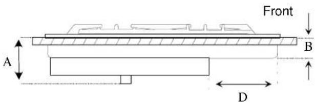
A-7½ inches
B-4 inches
D-6/16 inches
Duct Locations
Cooktop can be vented vertically or horizontally. If vented horizontally, vent air through exterior to left or rear wall if possible. If vented vertically, locate hole between floor joists.
Side View of Cooktop
A-6 inches
B-216 inches
C-3/8 inches
D-81/4 inches
E—12½ inches
Center Line of Cooktop Cutout
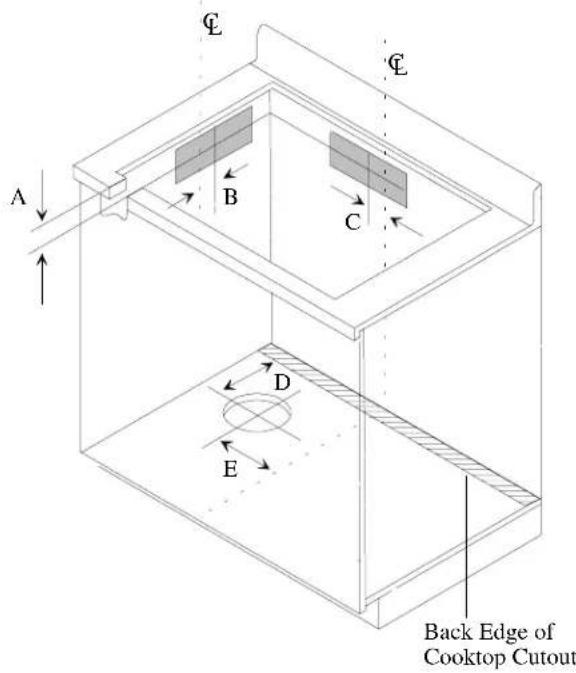
Square Blower Housing Duct Locations
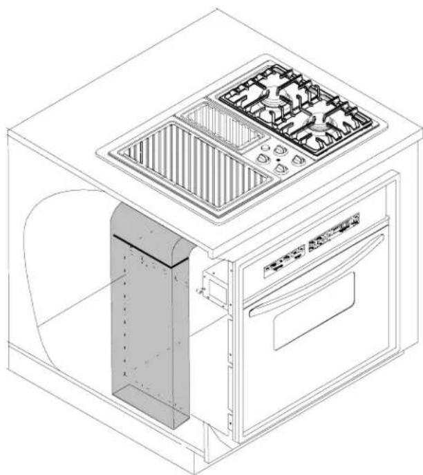
Vent Locations for Downdraft Cooktop above Undercounter Wall Oven
Downdraft Cooktop over Wall Oven in Standard Cabinet Locate cooktop exhaust ducts in grey areas.
A—6 inches
B-216 inches
C-3/8 inches
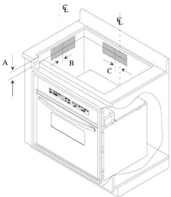
Downdraft Cooktop over Wall Oven in Standard Cabinet
Downdraft Cooktop over Wall Oven in Island
Locate cooktop exhaust ducts in grey areas.
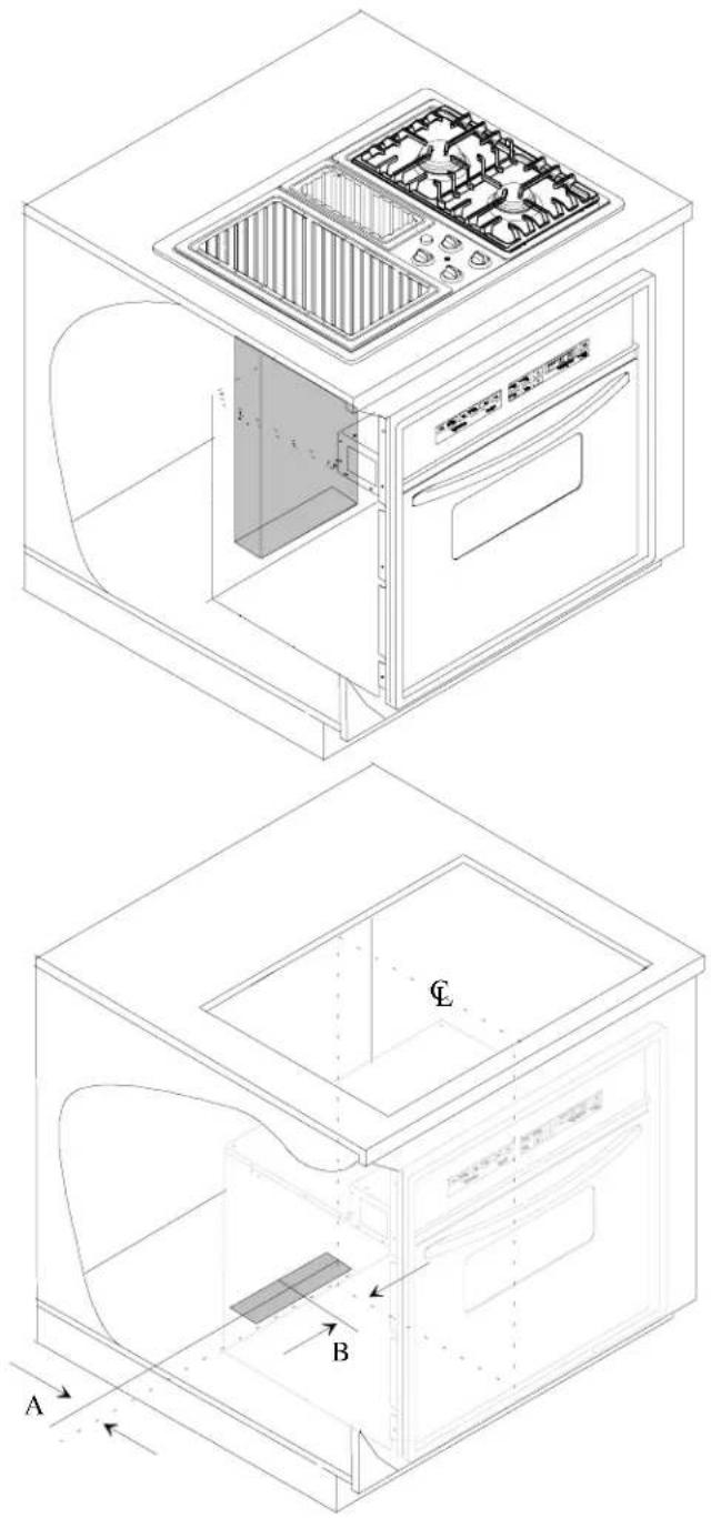
A-3/4 minimum
B- 3^1 / 8 inches
Rear Floor Exhaust
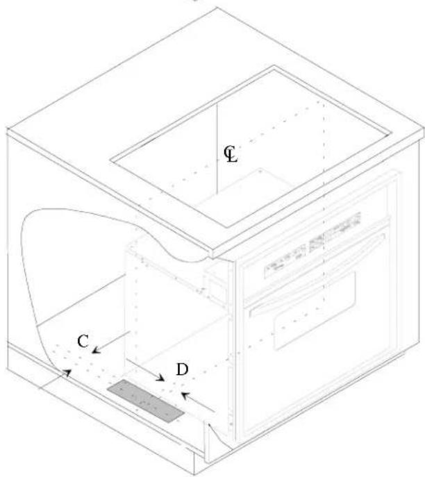
A-3/4 minimum
B-11/16 inch
Center Line
Duct Connections
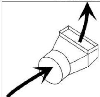
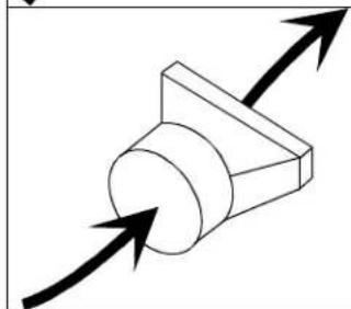
- Blower exhaust faces towards rear wall from factory. Blower can be changed to exhaust to left. Connect blower exhaust to ducting with 314 × 10 -inch piece.
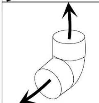
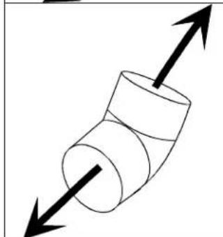
- Do not install 2 elbow fittings next to each other. Two elbow fittings joined together create unusual air patterns and can result in poor ventilation.
- Do not vent into an attic or crawl space. Always vent outside.
- Seal all joints in venting system with duct tape to avoid smoke or odor in home.
- Do not use laundry wall caps. Wall cap must have minimum of 28 square inches free air space. Use Amana wall cap model CC30.
Vertical and Left Duct Connection
To vent out left wall or vertically, remove vent filler piece and move to rear of blower.
- Remove 4 screws that attach vent filler.
See illustration. - Place vent filler on left side of blower housing.
- Attach vent filler with 4 screws.
Horizontal Rear Duct Connection
To vent out rear wall, do not move vent filler piece.
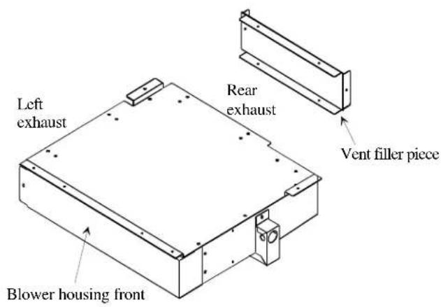
Blower Housing
Duct Length
Ducting design is in terms of maximum length of straight metal duct. To ensure proper air movement, limit fittings, other than straight, to 50% of total duct length. Maximum allowable calculated duct length is 60 equivalent feet.
- Use "Duct Length Piece Equivalents" section to calculate duct length.
- Flexible duct is not recommended because it can create a fire hazard. However, if it is used, one foot of flexible duct is equal to two feet of smooth metal duct.

Typical Duct System
Duct Length Piece Equivalents
| 3¼ x 10 inch ducting pieces | |
| 3¼ x 10-inch to 6 inch transition = 5 equivalent foot | |
| 3¼ x 10-inch to 6 inch transition = 4½ equivalent feet | |
| 3¼ x 10-inch flat elbow = 12 equivalent feet | |
| 3¼ x 10-inch 90° elbow = 5 equivalent feet | |
| 3¼ x 10-inch wall cap (Unrestricted) = 0 equivalent feet | |
6 inch ducting pieces
6-inch to 314 × 10 -inch transition = 5 equivalent feet
6-inch to 314 × 10 -inch transition = 1 equivalent foot
6-inch 90^ elbow = 5 equivalent feet
6-inch 45^ elbow = 2½ equivalent feet
6-inch wall cap (Unrestricted) = 0 equivalent feet (Amana wall cap model CC30)
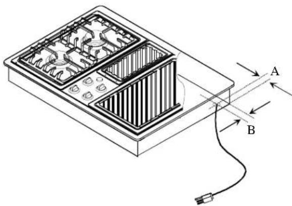
Gas and Electrical Entry Points
Gas and electric entry points are located in right rear corner of cooktop bottom. Dimensions are to center of connection.
A 43 / 4 inches B 3 / 4 inch
Gas Location
A—1 inch B—½ inch
Electrical Location
Gas and Electrical Installation Requirements
If an external electrical source is used when appliance is installed, it must be electrically grounded in accordance with local codes or, in absence of local codes, with current National Electrical Code ANSI NFPA 70, or CSA Standard C22.1, Canadian Electrical Code, Part 1.
When installed in mobile housing, installation is to be in accordance with CSA standard Z241.1 gas equipped mobile housing. All electrical connections are to be made in accordance with CSA standards Z240.6.1 electrical requirements for mobile homes.
The installation of appliances designed for manufactured (mobile) home installation must conform with Manufactured Home Construction and Safety Standard, Title 24 CFR, Part 3280, or when such standard is not applicable, the Standard for Manufactured Home Installation, ANSI225.1/NFPA 501A-Latest Edition, or with local codes or the standard CAN/CSA-z240MH, "Mobile Homes", and with local codes where applicable.
Installation of this product must conform with local codes or in absence of local codes, with current Canadian Gas Installation Code CAN/CGA-B149.2.
Use a dedicated 120 volt, 60 hertz, 3-prong receptacle protected by a 15-amp circuit breaker or time delay fuse. A qualified electrician should confirm the outlet is properly grounded. Cooktop includes 4-foot power cord attached to bottom of cooktop at back, right corner.
If a 2-prong outlet is encountered, cooktop owner must replace outlet before using cooktop. Do not cut off cord or remove grounding prong.
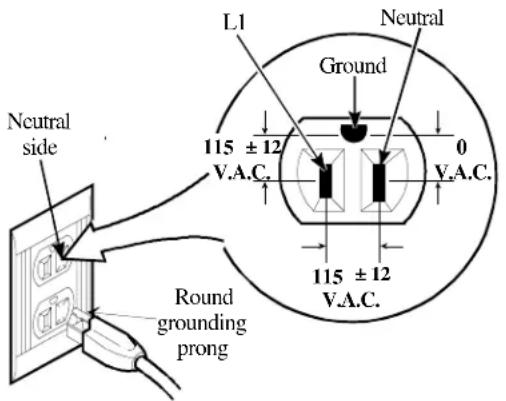
Standard 120 Volt, 60 Hertz
Junction Box Location
Power supply enters cooktop in right, rear corner. Junction box must be located within 30 inches of power supply entry point. Locate junction box within shaded area.
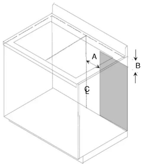
A—12 inches
B- 4% inches (From top of countertop)
C—24 inches
Center line
Junction Box Location
Gas Supply Location
Locate gas supply so manual shutoff valve is accessible after installation. Gas supply can be installed in adjacent cabinet or behind access panel.
Gas Supply Pressure

CAUTION
To avoid property damage, maximum gas supply pressure must not exceed 14" WCP.
- Appliance and individual shutoff valve must be disconnected from the gas supply piping system during any pressure testing of that system at test pressures higher than 1/2 psig (3.5kPa)(14" WCP).
- Appliance must be isolated from gas supply piping system by closing manual shutoff valve during any pressure testing of the gas supply piping system at test pressures equal to or less than 1/2 psig (3.5kPa) (14" WCP).
Gas supply pressure for checking regulator setting must be at least 1" WCP above manifold pressure shown on rating label. - Must use pressure regulator supplied with cooktop.
Gas Connection

WARNING
To avoid property damage or personal injury, only use a new flexible connector that is AGA/CGA design certified.
- Do not use an old connector.
- Do not reuse a connector after moving appliance.

WARNING
To avoid property damage or personal injury, do not use LP/propane gas to fuel this cooktop. Cooktop is not convertible to LP/propane gas.
Connect gas supply to regulator using hard pipe or a flexible connector. Pressure regulator supplied with this appliance has a 1/2 -inch NPT female connection.
- A manual shutoff, not supplied with cooktop, must be installed in an accessible location outside of cooktop.
- Use joint compound that is resistant to action of propane gas on all male pipe threads.
- Use supplied pressure regulator only.
- Do not overtighten gas fitting when attaching to pressure regulator. Overtightening may crack regulator.
- Support pressure regulator with wrench when installing gas fitting.
Refer to National Fuel Gas Code or local codes for supply pipe size requirements to assure sufficient gas supply to unit.
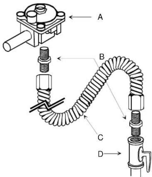
A—Regulator
B-Adaptor
C-Flexible Connector
D-Manual Shut Off Valve
Typical Flexible Connection
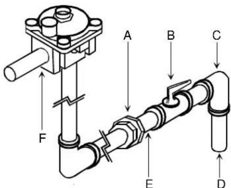
A—Union
B-Manual Shut Off Valve
C—Reducing Elbow (3/4-inch to 1/2-inch)
D-3/4-inch Stub
E-1/2-inch Nipple
F—Regulator
Typical Hardpipe Connection
Testing for Gas Leaks

WARNING
To avoid property damage or serious personal injury, never use a lighted match to test for gas leaks.
After final gas connection is made, test all connections in gas supply piping and cooktop for gas leaks.
- Place soap suds on connection.
- Bubbles appear if leak is present.
- Tighten joint if leak is at factory fitting.
If leak is not at factory fitting, unscrew, apply more joint compound, and tighten to correct leak. - Retest connection for leak after tightening.
- Retest any connections that were disturbed.
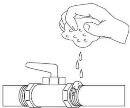
Test for Gas Leaks
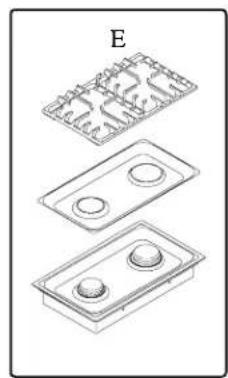
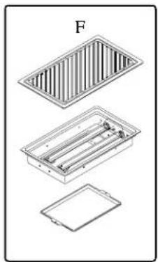
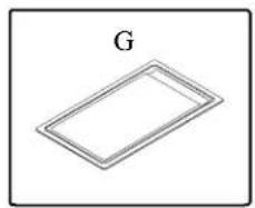
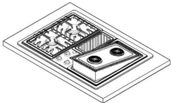
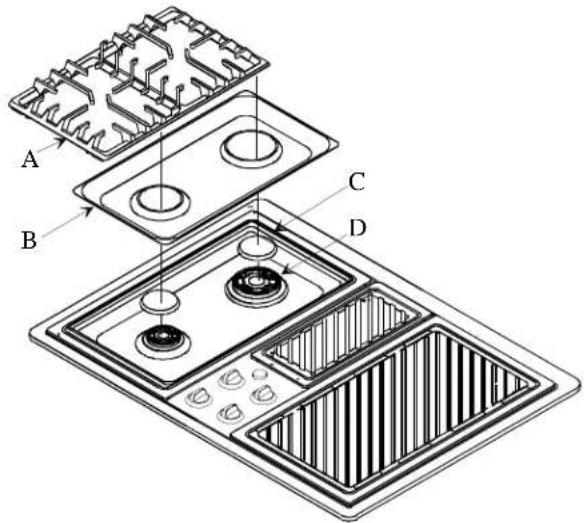
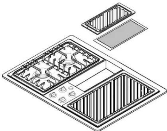
Cooktop Features
This cooktop features a choice of different cartridges, shown below. Cooktop is shipped with 1 sealed burner cartridge. Call your local authorized dealer or Amana at 1-800-843-0304 inside U.S.A. or 319-622-5511 outside U.S.A. to purchase additional accessories.
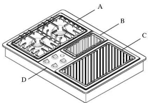
A—Sealed Burner Cartridge. Installs on either side.
B—Vent Cover with Removable Filter
C—Smoke Control Grill™ Cartridge. Installs on right side only.
D-Cooktop Control Panel
E—Sealed Burner Cartridge; Burner cartridge come from factory with cooktop.
F-Grill Cartridge.
G—Griddle Accessory. Griddle accessory installs on right side only.
Cooktop Features
Installing Cartridges

WARNING
To avoid risk of personal injury, all controls must be in OFF position before removing or installing.
Burner Cartridge
Burner cartridge installs on either side.
- Turn controls to OFF position.
-
Remove grate and burner caps from cartridge.
-
Place end of cartridge into cooktop well with air shutters facing rear of well.
-
If drip pan from grill or griddle cartridge is in well, remove before installing burner cartridge.
Installing Burner Cartridge
- Slide cartridge towards rear of cooktop until cartridge engages cooktop. Lower front of cartridge into well.
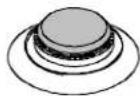
- Place burner caps on burner base.
A-Burner Grate
B-Burner Bowl
C-Burner Cap
D-Burner Base
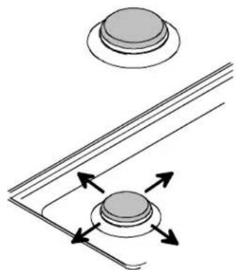
Place Burner Caps and Grate
To make sure cap is properly aligned and leveled, move burner cap around on burner base. Pegs in the burner base fit into recess in underside of burner cap. Burner cap must be correctly seated on burner base for proper operation of burner.
Make sure proper cap size is on each burner base. Burner does not burn properly if wrong size burner cap is placed on burner base.
Correct
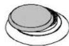
Not centered
Too small
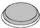
Too large
Position Burner Caps
- Ignite burner. Properly adjusted burner flames are clean and blue with a distinct inner cone approximately 1/2 inch long.
- If burner flame is blowing or noisy, or if burner flame is yellow and does not hold its shape, see "Adjusting Burner Flame Characteristics" section.
- Replace burner grate when flame is properly adjusted.
Smoke Control GrillTM
Install on right side only.
- Turn controls to OFF position.
- Remove grill from cartridge.
- Place drip pan in well.
- Place end of cartridge into cooktop well with air shutters facing rear of well. Lower front of cartridge into well.
- Place grill grate on cartridge.
Installing Smoke Control GrillTM
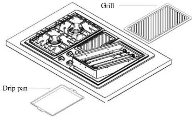
Installing Griddle
- Turn controls to OFF position.
- Install cartridge according to "Installing Smoke Control Grill™ Cartridge" section.
-
With grease trap toward rear of cooktop, place griddle pan over of burner.
-
To remove griddle cartridge turn all controls to OFF and reverse steps above.
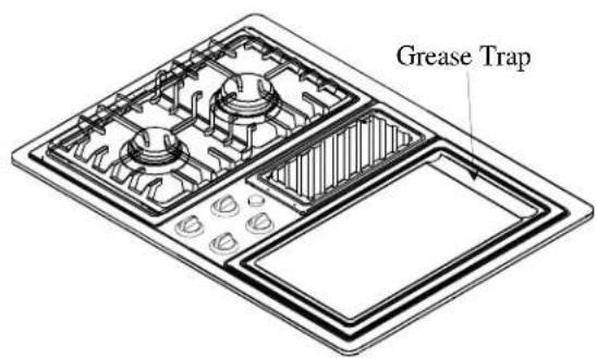
Installing Griddle
Removing Cartridges
- Turn all controls to OFF. Make sure cartridge is cool.
- Using tab on front of cartridge, lift up cartridge until the bottom clears the cooktop.
- Do not lift cartridge too high. Lifting cartridge too high can cause damage to orifices.
- Pull cartridge toward the front of cooktop and carefully lift it out.
Adjusting Surface Burner Low Flame Size
- Push and turn burner control knob to LITE position.
- Burner sparks until turned from LITE.
- Set burner control knob to low setting.
- Remove burner control knob.
- While holding valve stem stationary, turn screw in center of burner control stem until flame is adjusted.
- Use small blade screwdriver.
- Replace burner control knob.
- Turn surface burner control on and off to test burner flame.
- If flame is adjusted too low, flame may be easily extinguished. Flame may be extinguished by drafts, door opening or closing, heating and cooling vents, ceiling fans, etc.
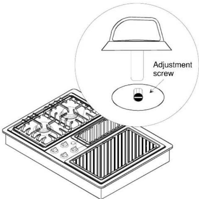
Adjusting Surface Burner Low Flame Size
Adjusting Burner Flame Characteristics
Surface burner should ignite within 4 seconds. Properly adjusted surface burner flames are clean and blue with a distinct inner cone approximately 1/4 inch to 1/2 inch long. Some yellow flame is normal when burning LP/Propane.
- If burner flame is blowing or noisy, reduce airflow to burner.
- If burner flame does not hold its shape, increase airflow to burner.
Adjusting Surface Burner Flame
- Turn controls to OFF position.
- Remove grate and burner caps from cartridge.
- Remove cartridge according to "Removing Cartridge" section.
- Locate air shutters on rear of cartridge.
- Adjust each air shutter using small screw driver. Slide air shutter until shutter is approximately 1/8 inch open.
- Replace cartridge according to "Installing Burner Cartridge" section and check for proper flame.
- Replace burner grate when flame is properly adjusted.
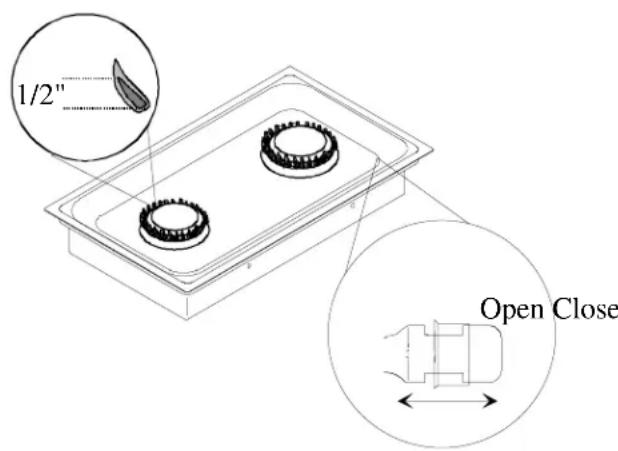
Adjusting Air Shutter
Adjusting Grill Cartridge Burner Flame
- Turn controls to OFF position.
- Remove grill or griddle from cartridge if necessary.
- Remove cartridge according to "Removing Cartridge" section.
- Locate air shutters on rear of cartridge, loosen air shutter lock screw, and open or close air shutter. Tighten air shutter lock screw after adjusting.
- Replace cartridge according to "Installing Burner Cartridge" section and check for proper flame.
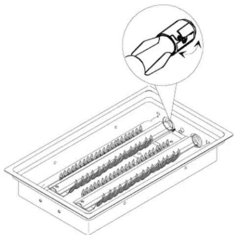
Adjust Grill Cartridge Burner Flame
Igniting Surface Burner without Electricity
If power is not available, ignite surface burner with a match. Do not ignite grill or griddle when power is not available.

WARNING
To avoid risk of personal injury, property damage, due to excessive smoke or fire, do not attempt to use grill or griddle, when power is not available. Fan must be running to exhaust smoke and fumes.
- Hold burning match 12 inch from burner head.
- Push and turn burner control knob to LITE position. Remove hand when burner ignites.
- Turn burner control knob to OFF position when finished.
Burner Cartridges

WARNING
To avoid risk of serious personal injury, property damage, or fire, do not leave surface burners unattended while in operation. Grease and spillovers can ignite causing a fire.
-
Push and turn burner control knob to LITE position.
-
Burner ignites.
- Burner sparks until turned from LITE.
-
Surface burner control does not stop at each setting.
-
Set burner control knob to desired setting.
- When finished cooking, turn control to OFF.
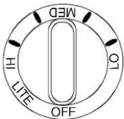
Surface Burner Control Knob
Delayed Ignition
Burner should ignite within 4 seconds. If burner does not ignite within 4 seconds turn control knob to OFF position and follow directions in "Installing Cartridges" section. Try burner again. If burner still does not ignite in 4 seconds, contact an authorized servicer.
Adjusting Burner Flame Size
- While turning the burner control knob, watch the burner flame.
- Flame size should match the size of the pan. Do not allow the flame to extend up the sides of the pan. Flames that extend up the sides of the pan can ignite clothing, make handle hot, or burn.
Cooking Utensils
For best cooking results, use a pan with proper characteristics.
Utensils Material Characteristics
| Type | Temperature Response | Uses |
| Aluminum | Heats and cools quickly | Frying, Braising, Roasting |
| Cast Iron | Heats and cools slowly | Low heat cooking, frying |
| Copper Tin Lined | Heats and cools quickly | Gourmet cooking, wine sauces, egg dishes |
| Enamelware | Depends on base metal | Low heat cooking |
| Ceramic (glass) | Heats and cools quickly | Low heat cooking |
| Stainless Steel | Heats and cools at moderate rate | Soups, sauscs, vegetables, general cooking |
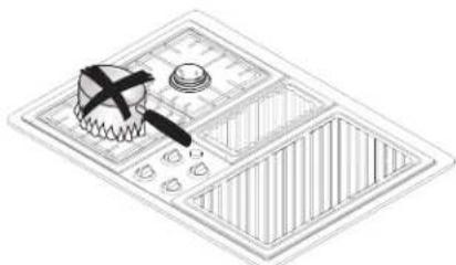
- Use proper pan size. Do not use utensils that overhang grate by more than 1 inch.
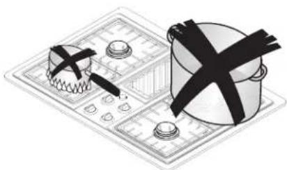
Incorrect Pan Sizes
- Use care when using glazed cooking utensils. Some glass, earthenware, or other glazed utensils break due to sudden temperature changes.
- Select utensils without broken or loose handles. Handles should not be heavy enough to tilt pan.
- Do not use a wok with a ring stand.
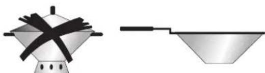
Woks
Adjusting Burner Flame Size
For best cooking results, use a pan with a flat bottom. Determine if pan has a flat bottom.
- Rotate a ruler along bottom of pan. If pan is not flat, gaps between bottom of pan and edge of ruler occur.
- A small groove or mark on a pan does not affect cooking times. However, if a pan has a gap, formed rings, or an uneven bottom, it does not cook efficiently and in some cases may not boil liquid.
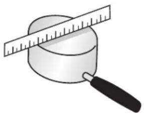
Use a Flat Pan
Smoke Control GrillTM
WARNING
To avoid risk of serious personal injury, property damage, or fire, do not leave surface burners unattended while in operation. Grease and spillovers can ignite causing a fire.
Important
To avoid damaging or removing nonstick surface, do not use metal cooking utensils on the grill.
- Before using grill for first time wash it with warm soapy water. Rinse and dry thoroughly. Lightly wipe top of grill surface with cooking oil to prevent food from sticking (do not use shortening or butter). Let cooking oil remain on grill surface.
- Trim excess fat from around meats to prevent smoking and flare-ups.
-
Push and turn back and front right burner control knobs to LITE position.
-
Burner sparks until burner control knob is turned from LITE.
-
Surface burner control does not stop at each setting.
Fan turns on at low speed. Adjust if necessary. -
Set burner control knob to desired setting and preheat for approximately 10 minutes.
-
Do not heat grill for extended periods on HI setting without food. Extreme temperatures may separate nonstick finish from metal.
-
Do not precook food before grilling unless it is immediately placed on grill.
-
Place food on grill.
-
Check that meats are done before removing them from grill. Meats often brown quickly on outside, but are not done in middle.
-
If meat begins to cook too quickly on outside, reduce grill heat.
-
When finished cooking, turn control to OFF.
-
Clean grill pan and smoke control grill.
-
Clean grill pan with soap and water.
- Clean smoke control grill in dishwasher or with soap and water.
- Always use nylon, hard rubber, or wooden kitchen tools on conventional nonstick finish.
- Do not clean griddle burner. Soil on burner burns off during subsequent use.
Griddle
WARNING
To avoid risk of serious personal injury, property damage, or fire, do not leave surface burners unattended while in operation. Grease and spillovers can ignite causing a fire.
Important
To avoid damaging or removing nonstick surface, do not use metal cooking utensils on the griddle.
-
Before using griddle for first time, wash with warm soapy water. Rinse and dry thoroughly. Lightly wipe top of griddle surface with cooking oil to prevent food from sticking (do not use shortening or butter). Let cooking oil remain on the surface.
-
Push and turn back and front right burner control knobs to LITE position.
-
Burner sparks until burner control knob is turned from LITE.
-
Surface burner control does not stop at each setting.
Fan turns on at low speed. Adjust if necessary. -
Set burner control knob to desired setting and preheat for approximately 10 minutes. Place food on griddle.
-
Do not allow the griddle pan to become full of grease. Clean after each use.
-
When finished cooking, turn control to OFF.
-
Clean grill pan and griddle.
-
Do not clean griddle burner. Soil on burner burns off during subsequent use.
- Always use nylon, hard rubber, or wooden kitchen tools on conventional no-stick finish.
Exhaust Fan
Variable speed fan is built into center of cooktop. Fan is located beneath vent area. Fan operation is necessary to remove cooking vapors, odors, and smoke.
-
Turn fan knob to desired setting.
-
Fan automatically turns on at low speed when using grill or griddle. Fan can be manually turned to high speed. Fan cannot be turned off while grill or griddle.
Fan can be used during any cooking operation or to ventilate cooking area. -
Clean vents frequently. Grease should not be allowed to accumulate on vent or filter.
-
Turn fan control knob to OFF when you are finished using it.

Exhaust Fan Control Knob
Removing Vent Filter
- Lift filter cover to remove vent filter.
- Duct filter lifts out of vent.
- Clean and reinstall filter and vent cover.
- Clean in the dishwasher or with damp cloth and soapy water.

WARNING
To avoid risk of smoke damage or fire, do not operate cooktop without filter.
Removing Vent Filter

WARNING
To avoid risk of electrical shock, personal injury, or death, make sure cooktop has been properly grounded and always disconnect it from main power supply before cleaning.
Removing Control Panel and Gasket
- Pull knobs off stems to remove glass panel.
- Lift glass out of control panel.
- Lift gasket out of control panel.
-
Replace gasket and knobs after cleaning.
-
Clean according to "Cooktop Surfaces" instructions in "Cleaning Cooktop" section.
- Dry gasket thoroughly before replacing.
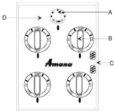
A—Fan control knob
B-Burner control knob
C—Gasket
D-Control panel
Control Panel
Cleaning
| Part Materials | to Use General Directions | |
| Burner caps and grates | Soap and Water Cool before cleaning. Frequent cleaning with soap and water, and non-abrasive pad prolongs time between deep cleanings. Be sure to dry thoroughly. | |
| Hard to clean burner caps and grates | 1/2 Cup Ammonia Place burner caps and grates in plastic bag with 1/2 cup ammonia. Do not pour ammonia into bag. Ammonia must remain in cup. To avoid rust, do not soak grates in ammonia. Close bag tightly and leave grate and caps overnight. Before bag is opened turn face away to avoid breathing or eye contact with fumes. Remove burner caps and grates from bag and rinse. Clean according to instructions above. | |
| Grill and griddle | Dishwasher or Soap and a Non-abrasive Plastic Scouring Pad | Clean in the dishwasher or with damp cloth and soapy water. If necessary, clean with nonabrasive cleaners or pads. Rinse and dry. |
| Drip pan Soap and water | Allow cooktop to cool before cleaning. Clean with damp cloth and soapy water. If necessary, clean with nonabrasive cleaners or pads. Rinse and dry. | |
| Burner cartridge | Soap and water | Allow cooktop to cool before cleaning. Food spilled on cartridge will burn off while cooking. Wipe with damp cloth and soapy water to clean around burner. Be sure to dry thoroughly. |
| Control knobs | Soap and Water | Pull off knobs. Wash gently but do not soak. Dry and return controls to oven, making sure to match flat area on the knob to the flat area on shaft. |
| Cooktop surfaces | Soap and water | Clean cooktop, knobs, control panel, and gasket under control knobs with damp cloth and soapy water. If necessary, clean with nonabrasive cleaners or pads. Dry thoroughly when finished to avoid rusting. Do not use harsh powders, oven cleaners, scouring pads, or steel wool. Gasket under control knobs can be removed for cleaning. |
| Fan cover and vent filter | Soap and water, or dishwasher | Fan must be off before removing filter cover. Clean filter and cover with damp cloth and soapy water. To remove grease and dried on soil, soak before cleaning. Rinse and dry after cleaning. Filter and filter cover can be cleaned in dishwasher. Always replace filter and cover before operating cooktop. |

COOKINGPRODUCTS(excludingwallovens)
FULL ONE YEAR WARRANTY
LIMITED SECOND YEAR WARRANTY ON ALL PARTS
LIMITED THIRD THRU FIFTH YEAR WARRANTY ON GLASS/CERAMIC TOP, ELECTRIC SURFACE ELEMENTS, OR GAS SURFACE BURNERS
FIRST YEAR
Amana Appliances will repair or replace, including related labor and travel, any part (f.o.b. Amana, Iowa) which proves to be defective as to workmanship or materials.
SECOND YEAR
Amana Appliances will provide replacement part, part only (f.o.b. Amana, Iowa), which proves defective as to workmanship or materials.
THIRD THRU FIFTH YEAR
Amana Appliances will provide replacement glass/ceramic cooktop, part only (f.o.b. Amana, Iowa), which proves defective as to workmanship or materials.
THIRD THRU FIFTH YEAR
Amana Appliances will provide replacement electric surface elements or gas surface burners, part only (f.o.b. Amana, Iowa), which proves defective as to workmanship or materials.
OWNER'S RESPONSIBILITIES:
- Provide any defective part to an authorized Amana servicer.
- Provide proof of purchase.
- Provide normal care and maintenance, including cleaning as instructed in owner's manual.
- Replace owner replaceable items where directions appear in the owner's manual.
Make product accessible for service. - Pay for premium service costs for service outside servicer's normal business hours.
- Pay for service calls related to product installation and customer education.
- Pay for servicer's labor and travel expenses under limited warranty provisions.
ITEMS NOT COVERED:
- Normal product maintenance and cleaning.
Light bulbs. - Damages which occur in shipment.
- General rebuilding or refurbishing that is not a legitimate warranty repair.
-
Failures caused by:
-
Unauthorized service.
- Grease or other material buildup due to improper cleaning or maintenance.
- Accidental or intentional damage.
- Connection to an improper gas or power supply.
- Acts of God.
- Use of improper pans, containers, or accessories that cause damage to the product.
WARRANTY LIMITATIONS:
- Begins at date of original purchase.
- Product used on a commercial, rental, or leased basis are not covered by this warranty.
- Applies to product used within the United States or in Canada if product has appropriate agency listing when shipped from the factory.
Service must be performed by an authorized Amana servicer.
Adjustments covered during first year only.
WARRANTY IS Void If:
- Serial plate is defaced
Product is altered by user. - Product is not installed or used according to manufacturer's instructions.
IN NO EVENT SHALL AMANA APPLIANCES BE LIABLE FOR INCIDENTAL OR CONSEQUENTIAL DAMAGES*
*This warranty gives you specific legal rights and you may have others which vary from state to state. For example, some states do not allow the exclusion or limitation of incidental or consequential damages so this exclusion may not apply to you.
For answers to questions regarding the above or to locate an authorized Amana® servicer, contact:
Amana Appliances
2800 220th Trail
USA
1-800-843-0304 inside U.S.A.
1-319-622-5511 outside U.S.A.
Identification du modele. 23