AKS3020L - Cooker AMANA - Free user manual and instructions
Find the device manual for free AKS3020L AMANA in PDF.

User questions about AKS3020L AMANA
0 question about this device. Answer the ones you know or ask your own.
Ask a new question about this device
Download the instructions for your Cooker in PDF format for free! Find your manual AKS3020L - AMANA and take your electronic device back in hand. On this page are published all the documents necessary for the use of your device. AKS3020L by AMANA.
USER MANUAL AKS3020L AMANA
Gas Cooktop Owner's Manual
AKS3020\* AKS3040\*
* Additional letters or numbers representing specific models or colors may follow each model number.
Please Read Manual Before Operating Cooktop
Important
Save for local electrical inspector's use.
Installer
Leave this manual and other literature with consumer for future use.
Customer
Keep these instructions for future reference. If appliance changes ownership, be sure this manual accompanies cooktop.
English....2 Français....14
Consumer Communications/Spanish Manual
2800 220th Trail
PO Box 8901
Amana, Iowa 52204-0001
USA
Model Identification 2
Parts and Accessories.... 2
Service 2
Asure™ Extended Service Plan 2
Important Safety Information ....3
ALL APPLIANCES....3
SURFACE COOKING UNITS 3
Delayed Ignition 4
VENTILATION HOOD 4
In Case of Fire 4
Precautions 4
Installation....5
Unpacking Cooktop....5
Countertop Cutout Dimensions.... 5
Securing Cooktop to Countertop 6
Converting Type 1 Pressure Regulator for Use with LP/Propane 7
Converting Type 2 Pressure Regulator for Use with LP/Propane 7
Converting Burners for Use with LP/Propane ...... 7
Converting Type 1 Pressure Regulator for Use with Natural Gas 7
Converting Type 2 Pressure Regulator for Use with Natural Gas 7
Converting Burners for Use with Natural Gas 8
Gas Supply Pressure....8
Gas Connection 8
Testing for Gas Leaks 9
Place Grates and Burner Caps....9
Electrical Installation Requirements 9
Operation 10
Operating Burners 10
Cooking Utensils.... 11
Adjusting Surface Burner Flame.... 12
Adjusting Air Shutter 12
Adjusting Surface Burner Low Flame Size 12
Operating Surface Burner during a Power Failure .... 12
Cleaning Cooktop, Burners, and Grates 12
Warranty 13
Model Identification
Complete enclosed registration card and promptly return. If registration card is missing, call Consumer Affairs Department at 1-800-843-0304 inside U.S.A. 319-622-5511 outside U.S.A. When contacting Amana, provide product information located on rating plate. Rating plate is located on bottom of cooktop. Record the following:
Model Number:
Manufacturing Number: ____
Serial or S/N Number: ____
Date of purchase: ____
Dealer's name and address: ____ ____
Parts and Accessories
Purchase replacement parts and additional accessories (e.g., refrigerator shelves, dryer racks, or cooktop modules) over the phone. To order accessories for your Amana product, call 1-800-843-0304 inside U.S.A. or 319-622-5511 outside U.S.A.
Service
Keep a copy of sales receipt for future reference or in case warranty service is required. Any questions or to locate an authorized servicer, call 1-800-NAT-LSVC (1-800-628-5782) inside U.S.A. 319-622-5511 outside U.S.A. Warranty service must be performed by an authorized servicer. Amana Appliances, also recommends contacting an authorized servicer if service is required after warranty expires.
Before Calling for Service
Review Owner's Manual before calling for service. If problems are not caused by defective workmanship or materials, or if part is customer replaceable, you could be charged for a service call though product is under warranty.
- If you hear gas hissing but burner does not click, check electrical supply.
- If burner flame is large and yellow, check if cooktop needs conversion to LP or natural gas.
- If burner flame is weak or noisy, see “Adjusting Surface Burner Flame” section of manual.
Asure™ Extended Service Plan
Amana Appliances offers long-term service protection for this new range. Asure™ Extended Service Plan is specially designed to supplement Amana's strong warranty. This plan covers parts, labor, and travel charges.
Call 1-800-528-2682 for information.

WARNING
This gas appliance contains or produces a chemical or chemicals which can cause death or serious illness and which are known to the state of California to cause cancer, birth defects or other reproductive harm. To reduce the risk from substances in the fuel or from fuel combustion make sure this appliance is installed, operated, and maintained according to the instructions in this booklet.

WARNING
To avoid risk of electrical shock, personal injury, or death, make sure your cooktop has been properly grounded and always disconnect it from main power supply before any servicing.

WARNING
To avoid death, personal injury or property damage, information in this manual must be followed exactly.
Do not store or use gasoline or other flammable vapors and liquids in the vicinity of this or any other appliance.
WHAT TO DO IF YOU SMELL GAS
- Do not try to light any appliance.
- Do not touch any electrical switch; do not use any phone in your building.
- Immediately call your gas supplier from a neighbor's phone. Follow the gas supplier's instructions.
- If you cannot reach your gas supplier, call the fire department.
Installation and service must be performed by a qualified installer, service agency or the gas supplier.

CAUTION
Do not obstruct the flow of combustion or ventilation air.
ALL APPLIANCES
- Proper Installation—Be sure your appliance is properly installed and grounded by a qualified technician.
- Never Use Appliance for Warming or Heating the Room.
- Do Not Leave Children Alone—Children should not be alone or unattended in the area where the appliance is in use. They should never be allowed to sit or stand on any part of the appliance.
- Wear Appropriate Apparel—Loose fitting or hanging garments should never be worn while using appliance.
- User Servicing—Do not repair or replace any part of the appliance unless specifically recommended in the manual. All other servicing should be referred to a qualified technician.
- Storage in or on Appliance—Flammable materials should not be stored in oven or near surface units.
- Do Not Use Water on Grease Fires—Smother fire or flame, or use dry chemical or foam-type extinguisher.
- Use Only Dry Potholders—Moist or damp potholders on hot surfaces may result in burns from steam. Do not let potholder touch elements. Do not use a towel or other bulky cloth.
SURFACE COOKING UNITS
- Use Proper Pan Size—This appliance is equipped with one or more surface burners of different sizes. Select utensils having flat bottoms large enough to cover the surface burner flame. The use of undersized utensils will expose a portion of the burner flame to direct contact and may result in ignition of clothing. Proper relationship of utensil to burner will also improve efficiency.
- Never Leave Surface Burners Unattended—Boilover causes smoking and greasy spillovers that may ignite.
- Protective Liners—Do not use aluminum foil to line around burners. Improper installation of these liners may result in a risk of electrical shock, or fire.
- Glazed Cooking Utensils—Only certain types of glass, ceramic, earthware, or other glazed utensils are suitable for rangetop service without breaking due to sudden change in temperature.
- Utensil Handles Should be Turned Inward and Not Extend Over Adjacent Surface Burners—To reduce the risk of burns, ignition of flammable materials, and spillage due to unintentional contact with the utensil, the handle of a utensil should be positioned so that it is turned inward, and does not extend over adjacent surface units.
Delayed Ignition
Surface Burners
Burner should ignite within 4 seconds. If burner does not ignite within 4 seconds turn control knob to OFF position and follow directions in "Placing Grates and Burner Caps" section. Try burner again. If burner still does not ignite in 4 seconds, contact an authorized servicer.
VENTILATION HOOD
- Clean Ventilation Hood Frequently—Grease should not be allowed to accumulate on hood or filter.
- When flaming foods under hood, turn fan off. The fan, if operating, may spread the flame.
In Case of Fire
Fires can occur as a result of over cooking or excessive grease. Though a fire is unlikely, if one occurs, proceed as follows:
Surface Burner Fire
- Smother the fire with a nonflammable lid or baking soda, or use a Class ABC or BC extinguisher. Not water. Not salt. Not flour.
- As soon as it is safe to do so, turn the surface burner controls to OFF.
- As an added precaution, turn off gas supply and power at main circuit breaker or fuse box.
Precautions
- Do not cook food directly on rangetop surface, always use cookware.
- Do not mix household cleaning products. Chemical mixtures may interact with objectionable or even hazardous results.
- Do not put plastic items on warm cooking areas. They may stick and melt.
- Do not slide rough metal objects across rangetop surface. Scratching or metal marking can result.
- Do not use damp sponge or dishcloth to clean rangetop when range is hot. Steam from sponge or dishcloth can burn.
- Do not leave fat heating unless you remain nearby. Fat can ignite if overheated by spilling onto hot surfaces.
- Do not allow pots to boil dry as this can cause damage to cooking surface and pan.
- Do not use rangetop surface as a cutting board.
Installation
Unpacking Cooktop
- Remove all packing and printed material packed with cooktop.
- Slide cooktop out of box.
- To avoid damage, do not slide cooktop across countertop.
- Remove grates, burner grates, burner bowls, and pressure regulator from box.
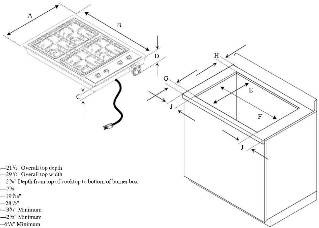
Countertop Cutout Dimensions
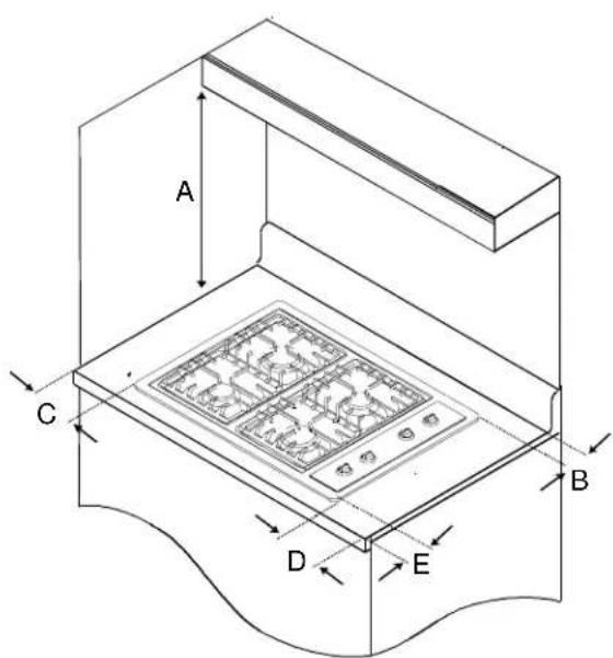
Prepare countertop opening according to dimensions shown in diagram. Given dimensions provide +1/16" to -0 clearance. Area beneath cooktop must be accessible for adjustment of gas pressure regulator.

WARNING
To avoid property damage or personal injury, observe the following specifications.
text_image
A B D C G H E F J -21½" Overall top depth -29½" Overall top width -27/8" Depth from top of cooktop to bottom of burner box -7½" -19¾16" -28½" -3¾4" Minimum -2½" Minimum -6¾8" MinimumCooktop and Countertop Dimensions
text_image
A C B D EA—30 inches between cooking surface and unprotected wood or metal cabinet above cooktop. 24 inches between cooking surface and protected wood or metal cabinet above cooktop. Cabinet bottom must be protected by at least 14 inch thick millboard with not less than No. 28 MSG sheet steel, .015 inch thick stainless steel, .024 inch thick aluminum, or .020 inch thick copper.
B—1 ^3 /8" minimum to rear wall from edge of cooktop.
C—5 ^7 /8" minimum to left side wall from edge of cooktop.
D—5 ^7 /s" minimum to right side wall from edge of cooktop.
E—2 1/2" minimum front dimension to front of countertop.
Minimum Clearances to Combustible Surfaces (All dimensions are for cooktop installed with controls on the right side.)
natural_image
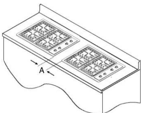
Isometric line drawing of a two-tiered electronic device with labeled component A (no text or symbols beyond label)A—Minimum of 6^1/4" must separate side flanges of cooktops installed side by side.
Cooktops Installed Side by Side
Securing Cooktop to Countertop
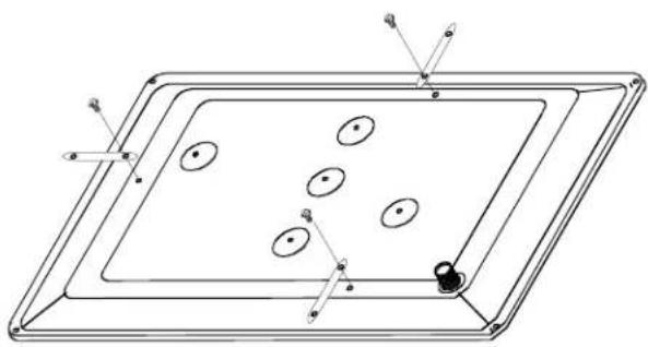
Mounting brackets enclosed in packet are to be attached to bottom of cooktop. Brackets will be used to secure cooktop to countertop.
- Insert cooktop in countertop cutout.
- Locate 3 screw holes for mounting brackets on the bottom of burner box as shown below.
natural_image
Technical line drawing of a rectangular tray with internal oval patterns and small circular features (no text or symbols)Mounting Brackets
-
Secure mounting brackets to burner box with mounting bracket screws provided.
-
Flat side of bracket mounts against bottom of burner box.
• Tinnerman nut extends beyond burner box. -
Do not overtighten mounting bracket screws.
-
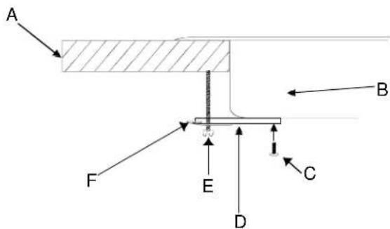
Install 3 adjusting screws into tinnerman nuts. Using blade screwdriver, tighten each adjusting screw so cooktop is secure against the countertop.
text_image
A B F E C DA—Countertop
B—Burner box
C—Mounting bracket screw
D—Mounting bracket
E—Adjusting screw
F—Tinnerman nut
Securing Cooktop to Coutnertop
Converting Type 1 Pressure Regulator for Use with LP/Propane
This cooktop arrives from factory adjusted for use with natural gas. If using LP/propane gas, cooktop must be converted.
- Remove pressure regulator cap using 58 " wrench.
-
Remove plastic insert from pressure regulator cap. • Plastic insert fits tightly in cap.
-
Reverse plastic insert and carefully push plastic insert firmly into hole in pressure regulator cap.
-
Insert must show "LPG10" or "LP10".
-
Place pressure regulator cap on pressure regulator and tighten.
- Insert should not disturb spring in body of regulator.
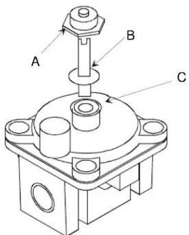
text_image
A B CA—Cap B—Plastic Insert (LP setting) C—Spring Location
Type 1 Pressure Regulator
Converting Type 2 Pressure Regulator for Use with LP/Propane
-
Remove pressure regulator cap using wrench.
-
Reverse pressure regulator cap.
-
Cap must show "LP".
-
Place pressure regulator cap on pressure regulator and tighten.
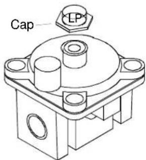
text_image
Cap LPType 2 Pressure Regulator
Converting Burners for Use with LP/Propane
- Remove control knobs, grates, caps, and burner bowls.
- Remove burners by removing burner screw with phillips screwdriver. Unplug burners from burner wires.
- Lift maintop off burner box to expose air shutters. • Orifice hoods will be visible.
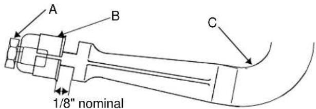
text_image
A B C 1/8" nominalA—Orifice Hood
B—Air Shutter
C—Venturi Tube
Converting Burners for Use with LP/Propane
-
Turn orifice hoods clockwise approximately 1 12 to 2 turns (close) until snug against pin. • Do not overtighten hoods to avoid damaging hoods.
-
Reassemble cooktop.
-
Adjust burner flame if necessary. • See "Adjusting Surface Burner Flame" section.
Converting Type 1 Pressure Regulator for Use with Natural Gas
- Remove pressure regulator cap using a 58 " wrench.
- Remove plastic insert from pressure regulator cap.
- Plastic insert fits tightly in cap.
- Reverse plastic insert and carefully push plastic insert firmly into hole in pressure regulator cap.
- Insert must show "NAT" or be blank.
- Place pressure regulator cap on pressure regulator and tighten.
- Insert should not disturb spring in body of regulator.
Converting Type 2 Pressure Regulator for Use with Natural Gas
-
Remove pressure regulator cap using 58 " wrench.
-
Reverse pressure regulator cap.
- Cap must show "NAT" or be blank.
- Place pressure regulator cap on pressure regulator and tighten.
Converting Burners for Use with Natural Gas
- Remove control knobs, grates, caps, and burner bowls.
- Remove burners by removing burner screw with Phillips screwdriver. Unplug burners from burner wires.
- Lift maintop off burner box to expose air shutters.
- Turn orifice hoods counterclockwise (open) approximately 1^1/2 to 2 turns.
- Reassemble cooktop.
- Adjust burner flame if necessary.
- See "Adjusting Surface Burner Flame" section.
Gas Supply Pressure

CAUTION
To avoid property damage, maximum gas supply pressure must not exceed 14" WCP.
- Appliance and individual shutoff valve must be disconnected from the gas supply piping system during any pressure testing of that system at test pressures in excess of 12 psig (3.5kPa)(14" WCP).
- Appliance must be isolated from gas supply piping system by closing manual shutoff valve during any pressure testing of the gas supply piping system at test pressures equal to or less than 12 psig (3.5kPa) (14" WCP).
- Gas supply pressure for checking regulator setting must be at least 1" WCP above manifold pressure shown on rating label.
- Must use pressure regulator supplied with cooktop.
Gas Connection
Connect gas supply to regulator using hard pipe or a flexible connector. Pressure regulator supplied with this appliance has a 12 " NPT female connection.
- A manual shutoff, not supplied with cooktop, must be installed in an accessible location outside of cooktop.
- Use joint compound that is resistant to action of propane gas on all male pipe threads.
- Use supplied pressure regulator only.
- Do not overtighten gas fitting when attaching to pressure regulator. Overtightening may crack regulator.
- Support pressure regulator with wrench when installing gas fitting.

WARNING
To avoid property damage or personal injury, only use a new flexible connector that is AGA/CGA design certified.
- Do not use an old connector.
- Do not reuse a connector after moving appliance.
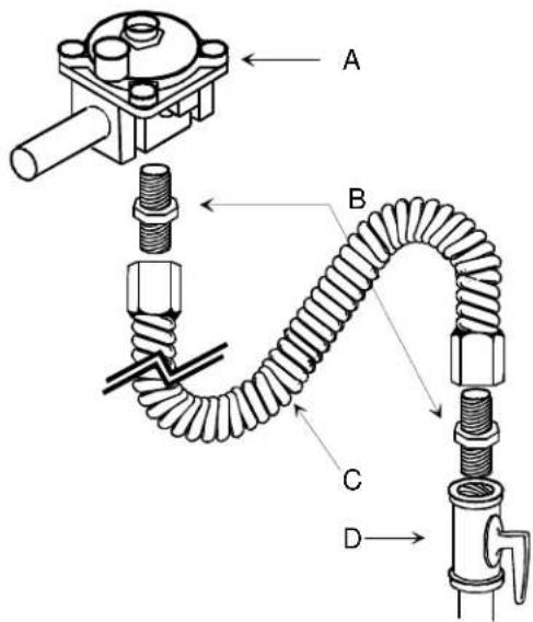
text_image
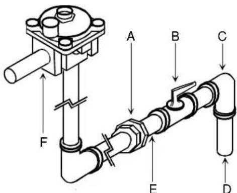
Technical diagram of a mechanical assembly with labeled parts A, B, C, and D showing components like bolts, springs, and tubing.A—Regulator
B—Adaptor
C—Flexible Connector
D—Manual Shut Off Valve
Flexible Connection
text_image
A B C D E FA—Union
B—Manual Shut Off Valve
C—Reducing Elbow (3/4-inch to 1/2-inch)
D—3/4-inch Stub
E—1/2-inch Nipple
F—Regulator
Hardpipe Connection
Testing for Gas Leaks

WARNING
To avoid property damage or serious personal injury, never use a lighted match to test for gas leaks.
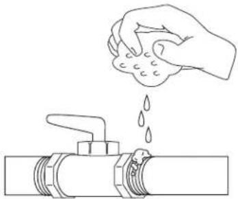
After final gas connection is made, test all connections in gas supply piping and cooktop for gas leaks.
- Place soap suds on connection.
- Bubbles appear if leak is present.
natural_image
Line drawing of a hand pouring liquid into a pipe fitting (no text or symbols)Testing for Gas Leaks
- Tighten joint if leak is at factory fitting.
- If leak is not at factory fitting, unscrew, apply more joint compound, and tighten to correct leak.
- Retest connection for leak after tightening.
- Retest any connections that were disturbed.
Place Grates and Burner Caps
text_image
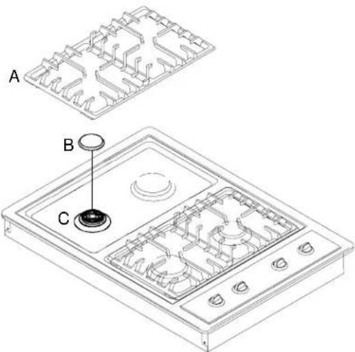
A B CA—Burner grate
B—Burner cap
C—Burner base
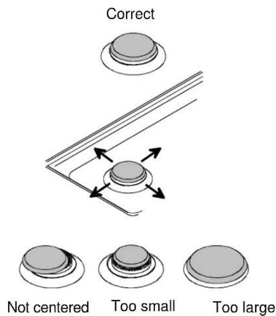
To make sure cap is properly aligned and leveled, move burner cap around on burner base. Pegs in the burner base fit into recess in underside of burner cap. Burner cap must be correctly seated on burner base for proper operation of burner.
Make sure proper cap size is on each burner base. Burner does not burn properly if wrong size burner cap is placed on burner base.
Turn on burners to check for proper operation. See Operating Surface Burners section for burner operating instructions.
text_image
Correct Not centered Too small Too largeBurner Caps
Electrical Installation Requirements
Installation of this product must conform with local codes or in absence of local codes, with current Canadian Gas Installation Code CAN/CGA-B149.2. If an external electrical source is used when appliance is installed, it must be electrically grounded in accordance with local codes or, in absence of local codes, with current National Electrical Code ANSI NFPA 70, or CSA Standard C22.1, Canadian Electrical Code, Part 1.
All electrical connections are to be made in accordance with CSA Standards Z240.6.1 electrical requirements for mobile homes.
Place Grates and Burner Caps
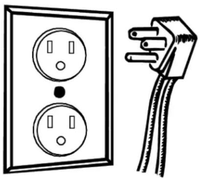
Use a dedicated 120 volt, 60 hertz, 3-prong receptacle protected by a 15 amp circuit breaker or time delay fuse. A qualified electrician should confirm the outlet is properly grounded. Cooktop includes 4-foot power cord attached to bottom of cooktop.
natural_image
Electrical socket and plug diagram (no text or symbols)Grounded Plug and Receptacle
If a 2-prong outlet is encountered, cooktop owner must replace outlet before using cooktop. Do not cut off cord or remove grounding prong.
When installed in mobile housing, installation is to be in accordance with CSA standard Z241.1 gas equipped mobile housing. All electrical connections are to be made in accordance with CSA standards Z240.6.1 electrical requirements for mobile homes.
The installation of appliances designed for manufactured (mobile) home installation must conform with Manufactured Home Construction and Safety Standard, Title 24 CFR, Part 3280, or when such standard is not applicable, the Standard for Manufactured Home Installation, ANSI225.1/NFPA 501A-Latest Edition, or with local codes or the standard CAN/CSA-z240MH, "Mobile Homes", and with local codes where applicable.
The installation of appliances is to be in accordance with CAN1-B149.1 or B149.2 installation code for gas burning appliances and equipment and/or local codes. Part 1 and/or local codes.
All electrical connections are to be made in accordance with CSA C22.1 Canadian Electrical Code.
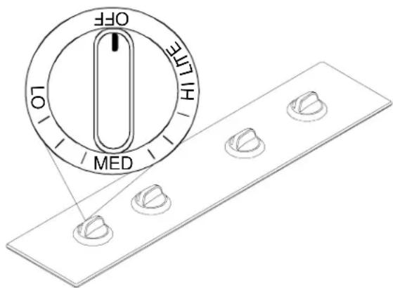
Operating Burners
- Push and turn burner control knob to "LITE" position.
- Burner sparks until turned from "LITE".
-
Turn burner control knob to desired setting.
-
Turn burner control knob to "OFF" position when finished.
- Refer to cooktop rating plate for individual burner ratings.
text_image
OFF LO HI HE MEDSurface Burner Controls
Delayed Ignition
Burner should ignite within 4 seconds. If burner does not ignite within 4 seconds turn control knob to OFF position and follow directions in "Placing Grates and Burner Caps" section. Try burner again. If burner still does not ignite in 4 seconds, contact an authorized servicer.
Burner Flame Size
- While turning the burner control knob, watch the burner flame.
- Flame size should match the size of the pan. Do not allow the flame to extend up the sides of the pan. Flames that extend up the sides of the pan can ignite clothing, make handle hot, or burn.
natural_image
Isometric line drawing of a gas stove with a valve and fan (no text or symbols)Burner Flame Size
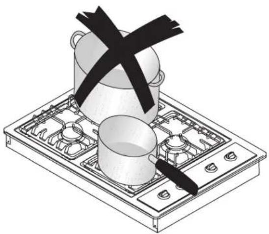
Cooking Utensils
- Use proper pan size. Do not use a pan that has a smaller bottom than surface burner. Do not use utensils that overhang grate by more than 1 inch.
natural_image
Illustration of a cooking pot and a cooking pan on a gas stove (no text or symbols)Proper Pan Size
- Use care when using glazed cooking utensils. Some glass, earthenware, or other glazed utensils break due to sudden temperature changes.
- Select utensils without broken or loose handles.
- Handles should not be heavy enough to tilt pan.
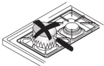
- Do not use stove top grills on your range. Stove top grills cause incomplete combustion and can create levels of carbon monoxide above allowable standards.
- Do not use a wok with a ring stand. Use flat bottom wok.
| Utensil Material Characteristic | ||
| Type Temperature | Response | Uses |
| Aluminum Heats and cools quickly | Frying, braising, roasting | |
| Cast Iron Heats and cools slowly | Low heat cooking, frying | |
| Copper Tin Lined | Heats and cools quickly | Gourmet cooking, wine sauces, egg dishes |
| Enamelware Depends on base metal | Low heat cooking | |
| Ceramic (Glass) Heats and cools slowly | Low heat cooking | |
| Stainless Steel Heats and cools at moderate rate | Soups, sauces, vegetables, general cooking | |
To avoid pan wobbling, use a pan with a flat bottom. Determine if pan has a flat bottom.
- Rotate a ruler along bottom of pan. If pan is not flat, gaps between bottom of pan and edge of ruler occur.
- A small groove or mark on a pan does not effect cooking times. However, if a pan has a gap, formed rings, or an uneven bottom, it does not cook efficiently and in some cases may not boil liquid.
Flat Pan
Wok
Adjusting Surface Burner Flame
Properly adjusted surface burner flames are clean and blue with a distinct inner cone approximately 14 inch to 12 inch long. See "Operating Burners" section for burner operating instructions.
- If burner flame is blowing or noisy, reduce airflow to burner by adjusting air shutter.
- If burner flame is yellow and does not hold its shape, increase airflow to burner by adjusting air shutter.
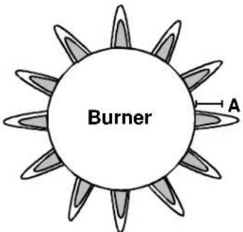
text_image
Burner AA— ^1 /4" to ^1 /2" inner cone length
Surface Burner Flame
Adjusting Air Shutter
- Remove control knobs, grates, caps, and burner bowls.
- Remove burners by removing burner screw with phillips screwdriver. Unplug burners from burner wires.
- Lift top up off burner box to expose air shutters.
- Slide air shutter open or closed depending on appearance of burner flame.
- If flame is yellow and does not hold its shape, open air shutter.
- If flame is blowing or noisy, close air shutter.
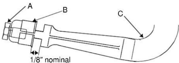
text_image
A B C 1/8" nominalA—Orifice Hood B—Air Shutter C—Venturi Tube
Air Shutter
- Reassemble.
- After adjustment retest burner flame.
Adjusting Surface Burner Low Flame Size
- Push and turn burner control knob to "LITE" position.
- Burner sparks until turned from "LITE".
- Set burner control knob to low setting.
- Remove burner control knob.
- While holding valve stem stationary, turn screw in center of burner control stem until flame is adjusted.
- Use small blade screwdriver.
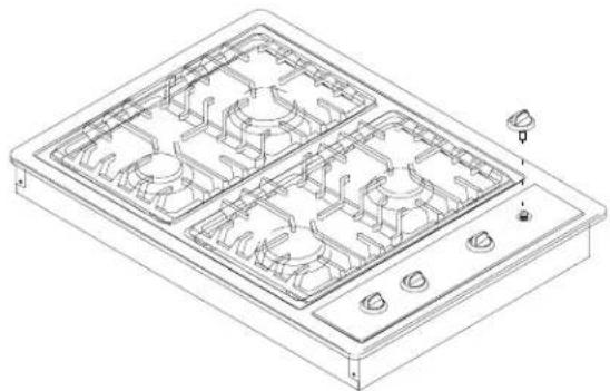
natural_image
Technical line drawing of a four-gas stove with mounting flanges and control knobs (no text or symbols)Adjusting Surface Burner Low Flame Size
- Replace burner control knob.
- Turn surface burner control on and off to test burner flame.
- If flame is adjusted too low, flame may be easily extinguished. Flame may be extinguished by drafts, door opening or closing, heating and cooling vents, ceiling fans, etc.
Operating Surface Burner during a Power Failure
Although the system that lights the burners is electric, surface burners can be ignited during a power failure.
Never attempt to light bake or broil burners during power failure.
- Hold ignited match at base of desired burner.
- Push in burner control knob and turn to LITE position.
- After gas ignites, remove match from burner and turn burner control knob to desired setting.
Cleaning Cooktop, Burners, and Grates
Clean cooktop, caps, and grates using damp cloth and soapy water. If necessary, clean with nonabrasive cleaners or pads. Dry thoroughly when finished to avoid rusting.
- Do not use harsh powders, oven cleaners, scouring pads, or steel wool.
Amana®COOKING PRODUCTS (excluding wall ovens)
FULL ONE YEAR WARRANTY
LIMITED SECOND YEAR WARRANTY ON ALL PARTS
LIMITED THIRD THRU FIFTH YEAR WARRANTY ON GLASS/CERAMIC TOP, ELECTRIC SURFACE ELEMENTS, OR GAS SURFACE BURNERS
FIRST YEAR
Amana Appliances will repair or replace, including related labor and travel, any part (f.o.b. Amana, Iowa) which proves to be defective as to workmanship or materials.
SECOND YEAR
Amana Appliances will provide replacement part, part only (f.o.b. Amana, Iowa), which proves defective as to workmanship or materials.
THIRD THRU FIFTH YEAR
Amana Appliances will provide replacement glass/ceramic cooktop, part only (f.o.b. Amana, Iowa), which proves defective as to workmanship or materials.
THIRD THRU FIFTH YEAR
Amana Appliances will provide replacement electric surface elements or gas surface burners, part only (f.o.b. Amana, Iowa), which proves defective as to workmanship or materials.
OWNER'S RESPONSIBILITIES:
- Provide any defective part to an authorized Amana servicer.
- Provide proof of purchase.
- Provide normal care and maintenance, including cleaning as instructed in owner's manual.
- Replace owner replaceable items where directions appear in the owner's manual.
- Make product accessible for service.
- Pay for premium service costs for service outside servicer's normal business hours.
- Pay for service calls related to product installation and customer education.
- Pay for servicer's labor and travel expenses under limited warranty provisions.
ITEMS NOT COVERED:
• Normal product maintenance and cleaning.
• Light bulbs.
• Damages which occur in shipment.
- General rebuilding or refurbishing that is not a legitimate warranty repair.
- Failures caused by:
- Unauthorized service.
- Grease or other material buildup due to improper cleaning or maintenance.
- Accidental or intentional damage.
- Connection to an improper gas or power supply.
- Acts of God.
- Use of improper pans, containers, or accessories that cause damage to the product.
WARRANTY LIMITATIONS:
- Begins at date of original purchase.
- Product used on a commercial, rental, or leased basis are not covered by this warranty.
- Applies to product used within the United States or in Canada if product has appropriate agency listing when shipped from the factory.
• Service must be performed by an authorized Amana servicer. - Adjustments covered during first year only.
WARRANTY IS VOID IF:
- Serial plate is defaced.
• Product is altered by user. - Product is not installed or used according to manufacturer's instructions.
IN NO EVENT SHALL AMANA APPLIANCES BE LIABLE FOR INCIDENTAL OR CONSEQUENTIAL DAMAGES\*
*This warranty gives you specific legal rights and you may have others which vary from state to state. For example, some states do not allow the exclusion or limitation of incidental or consequential damages so this exclusion may not apply to you.
For answers to questions regarding the above or to locate an authorized Amana® servicer, contact:
Amana Appliances
2800 220th Trail
PO Box 8901
Amana, Iowa 52204-0001
USA
1-800-843-0304 inside U.S.A.
1-319-622-5511 outside U.S.A.
natural_image
Isometric line drawing of a two-tiered electronic device with labeled component A (no text or symbols beyond label)natural_image
Technical line drawing of a rectangular tray with internal oval patterns and labeled points (no text or symbols)text_image
A B C 1/8" nominaltext_image
Technical diagram of a mechanical assembly with labeled parts A, B, C, and D showing components like bolts, springs, and tubing.natural_image
Line drawing of a hand pouring liquid into a pipe with a valve (no text or symbols)natural_image
Electrical socket and plug diagram (no text or symbols)text_image
OFF LIFE LIFE MEDnatural_image
Isometric line drawing of a gas stove with heating elements and a valve (no text or symbols)natural_image
Illustration of a cooking setup with a pot, stove, and double-headed iron (no text or symbols)Plats de cuisson
natural_image
Illustration of a traditional fire extinguisher with a black bandage and a flat pan (no text or symbols)Woks