CPA116W - Projector Accessory Chief - Free user manual and instructions
Find the device manual for free CPA116W Chief in PDF.

| Product Type | Projector mounting plate (ceiling mount accessory) |
| Brand | Chief |
| Model | CPA116W |
| Maximum load capacity | 34.02 kg (combined weight of mounting system) |
| Compatibility | CPA extension columns (not included) and RPEU, RPEUW, RPMEU, RPMEUW, RSEU, RSEUW, RSMEU, RSMEUW projector mounts |
| Mounting types | Wood ceiling (double stud 5x10 cm), concrete ceiling (min. thickness 20.3 cm), suspended ceiling on metal profile |
| Material | Steel |
| Color | White (likely, based on the "W" reference) |
| Plate dimensions | Approximately 20 cm x 20 cm (estimated) |
| Product weight | Approximately 1.5 kg (estimated) |
| Ceiling fixation | 4 fixation points (lag screws, threaded rods, or concrete anchors depending on ceiling type) |
| Required hardware (not included) | Lag screws 8 mm x 7 mm, threaded rods 9.5 mm, nuts, washers, UX10 or AF8 anchors |
| Usage | Indoor only |
| Installation | Requires professional installer; follow safety guidelines |
| Warranty | Standard manufacturer warranty (not specified) |
Frequently Asked Questions - CPA116W Chief
User questions about CPA116W Chief
0 question about this device. Answer the ones you know or ask your own.
Ask a new question about this device
Download the instructions for your Projector Accessory in PDF format for free! Find your manual CPA116W - Chief and take your electronic device back in hand. On this page are published all the documents necessary for the use of your device. CPA116W by Chief.
USER MANUAL CPA116W Chief
INSTALLATION INSTRUCTION INSTRUCTIONS D'INSTALLATION
MONTAGEANLEITUNG
Flat Pin Connect Ceiling Plate
Milestone AV Technologies and its affiliated corporations and subsidiaries (collectively "Milestone"), intend to make this manual accurate and complete. However, Milestone makes no claim that the information contained herein covers all details, conditions or variations, nor does it provide for every possible contingency in connection with the installation or use of this product. The information contained in this document is subject to change without notice or obligation of any kind. Milestone makes no representation of warranty, expressed or implied, regarding the information contained herein. Milestone assumes no responsibility for accuracy, completeness or sufficiency of the information contained in this document.
Chief® is a registered trademark of Milestone AV Technologies. All rights reserved.

IMPORTANT SAFETY INSTRUCTIONS

WARNING: A WARNING alerts you to the possibility of serious injury or death if you do not follow the instructions.

CAUTION: A CAUTION alerts you to the possibility of damage or destruction of equipment if you do not follow the corresponding instructions.

WARNING: Failure to read, thoroughly understand, and follow all instructions can result in serious personal injury, damage to equipment, or voiding of factory warranty! It is the installer's responsibility to make sure all components are properly assembled and installed using the instructions provided.

WARNING: Failure to provide adequate structural strength for this component can result in serious personal injury or damage to equipment! It is the installer's responsibility to make sure the structure to which this component is attached can support five times the combined weight of all equipment. Reinforce the structure as required before installing the component. The ceiling to which the mount is being attached may have a maximum drywall thickness of 5/8 (1.6cm).

WARNING: Exceeding the weight capacity can result in serious personal injury or damage to equipment! It is the installer's responsibility to make sure the combined weight of all components located within the mounting system of the CPA116 does not exceed 75 lbs (34.02 kg).
- The weight capacity of the CPA116 may be LIMITED to the lowest weight capacity of any other component or accessory used within the mounting system.

WARNING: Use this mounting system only for its intended use as described in these instructions. Do not use attachments not recommended by the manufacturer.

WARNING: Never operate this mounting system if it is damaged. Return the mounting system to a service center for examination and repair.

WARNING: Do not use this product outdoors.
NOTE: Accessory is intended to be used with the UL Listed CPA Extension Column Series (not included) and RPEU, RPEUW, RPMEU, RPMEUW, RSEU, RSEUW, RSMEU or RSMEUW projector mounts (not included).
IMPORTANT ! : These CPA mounts are designed to be:
- mounted to a double 2^ × 4^ wood framework ceiling;
- mounted to an 8'' concrete ceiling;
- mounted to a suspended metal framing channel ceiling.

WARNING: Do NOT attach to vertical mounting surfaces such as walls or angled ceilings!
--SAVE THESE INSTRUCTIONS--
DIMENSIONS
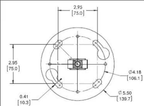
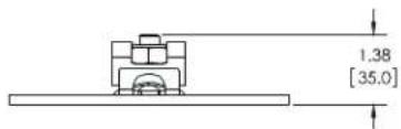
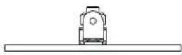
DIMENSIONS: INCHES [MILLIMETERS]
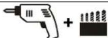
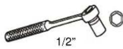
TOOLS REQUIRED FOR INSTALLATION
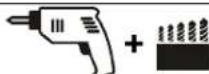
7/32" (wood studs)
3/8" (concrete-UX10 anchors)
5/16" (concrete-AF8 anchors)
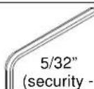
included)
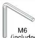
(included)
HARDWARE REQUIRED (NOT INCLUDED)--Dependent on installation method
- Install to wood ceiling joists
5 / 16^ × 2 - 3 / 4^ (minimum length) lag screws (Qty. 4)
-
Install to threaded rod
-
3/8" ASTM A307 threaded rods, 16 threads/square inch (Qty. 4)
- 3/8" channel nuts (Qty. 4)
- 3/8 jam nuts (Qty. 8)
-
3/8 washers (Qty. 8)
-
Install to solid concrete
UX10 or AF8 anchors (Qty. 4)
- 5/16" flat washers (Qty. 4)
- 5/16" x 2-3/4" bolts (Qty. 4)
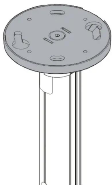
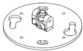
PARTS

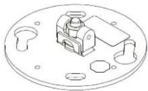
A (1)
(CPA116)
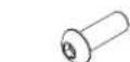
C (2) M6 x14mm

D (2) M6x16mm (security)
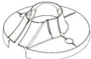
B (1) [Ceiling plate cover]

E (2) M6 x 6mm


LEGEND
| Tighten Fastener Apretar elemento de fijación Befestigungsteil festziehen Apertar fixador Serrare il fissaggio Bevestiging vastdraaien Serrez les fixations | Pencil Mark Marcar con lápiz Stiftmarkierung Marcar com lápis Segno a matita Potloodmerkteken Marquage au crayon |
| Loosen Fastener Aflojar elemento de fijación Befestigungsteil lõsen Desapertar fixador Allentare il fissaggio Bevestiging losdraaien Desserrez les fixations | Drill Hole Perforar Bohrloch Fazer furo Praticare un foro Gat boren Percez un trou |
| By Hand A mano Von Hand Com a mão A mano Met de hand À la main | Socket Wrench Llave de cubo Steckschlüssel Chave de caixa Chiave a brugola Dopsleutel Clé à douilles |
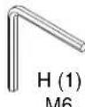
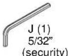
| Hex-Head Wrench Llave de cabeza hexagonal Sechskantschlüssel Chave de cébaça sextavada Chiave esagonale Zeskantsleutel Clé à tête hexagonale | Security Wrench Llave de seguidad Sicherheitschlüssel Chave de segurança Chiave di sicurezza Veiligheidsleutel Clé de sécurité |
INSTALLATION
IMPORTANT ! : The CPA116 must be attached to the extension column prior to attaching ceiling plate to the ceiling!
Attaching to Ceiling Column
- Place extension column (not included) over CPA116 (A) pin connector, lining up holes on pipe with holes in pin. (See Figure 1)
- Use two M6 x 16mm button head cap screws (C) or two M6 x 16mm button head security screws (D), two M6 lock washers (F) and two M6 flat washers (G) to secure extension column to connector pin. (See Figure 1)
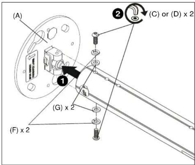
Figure 1
- Tighten screw on top of CPA116 plate to fully secure plate to connector pin. (See Figure 2)
IMPORTANT ! : To ensure a secure connection, make sure metal tabs are clearly visible after tightening bolt. (See Figure 2)
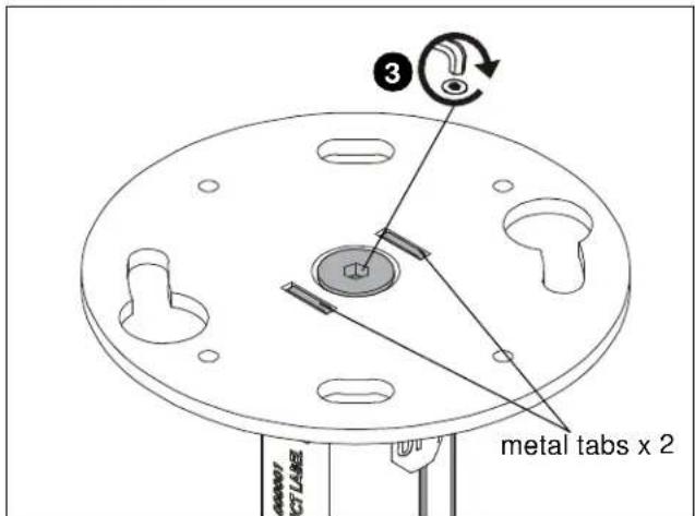
Figure 2
Connecting to Ceiling
These CPA mounts are designed for attachment to a double 2^ x 4" wood framework ceiling, a concrete ceiling or a suspended metal framing channel ceiling.

WARNING: Do NOT attach to vertical mounting surfaces such as walls or angled ceilings!

WARNING: IMPROPER INSTALLATION CAN LEAD TO LIFT FALLING CAUSING SEVERE PERSONAL INJURY OR DAMAGE TO EQUIPMENT! It is the installer's responsibility to make certain the structure to which the mount is being attached is capable of supporting five times the weight of the CPA mount and all attached equipment. Reinforce the structure as required before installing the mount.
NOTE: The following instructions assume a suitable mounting structure and surface exists prior to installation.
Installing to a Wood Framework (Joists)
IMPORTANT ! : The CPA116 is designed to be mounted to double 2^ × 4^ wood stud cross bracing (5" on center) between two ceiling joists with a maximum drywall covering of 5 / 8
- Using ceiling plate (A) as a template, mark locations of four pilot holes (See Figure 3). Ensure the marks are in the center of wood joists.
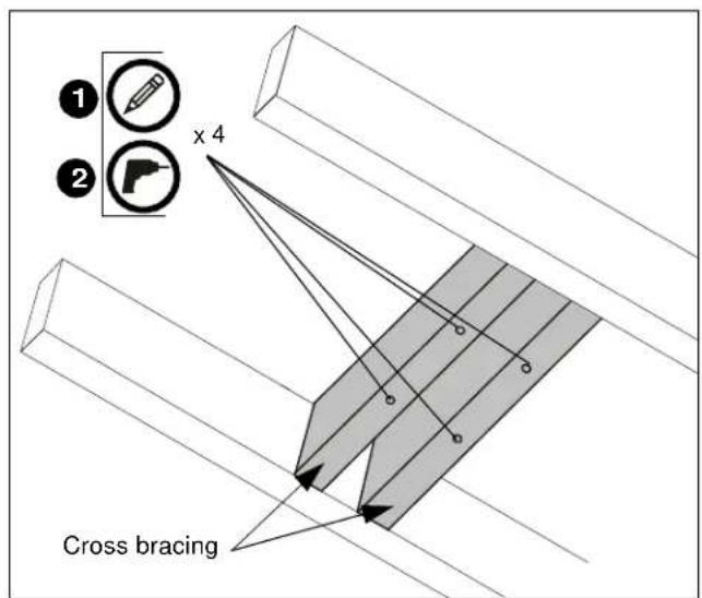
Figure 3
-
Drill 7/32" diameter pilot holes into wood stud cross bracing. (See Figure 3) Ensure pilot holes are straight.
-
Loosely install two 5 / 16'' x 2-3/4" (minimum) lag screws (not included) through two 5 / 16'' washers (not included) into opposite corners of holes drilled in wood stud cross bracing. (See Figure 4)
- Place ceiling plate (A) up to ceiling and turn until lag screws hold plate up in position. (See Figure 4)
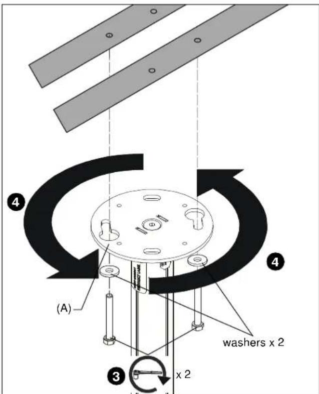
Figure 4
- Install two 5 / 16'' x 2-3/4" (minimum) lag screws (not included) through holes on ceiling plate (A) and into holes drilled in wood stud cross bracing. (See Figure 5)
- Tighten all four lag screws to secure plate to ceiling. (See Figure 5)
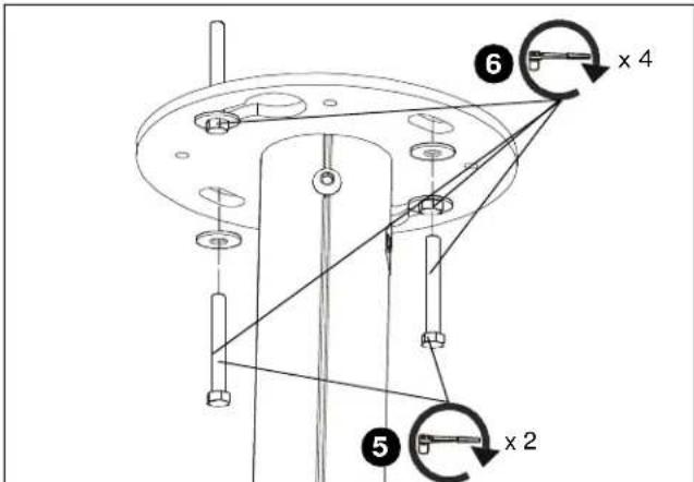
Figure 5
Installing to a Suspended Ceiling
NOTE: The CPA mount may be suspended from four 3/8 in. diameter threaded rods (not included) which are secured to a 1 - 5 / 8'' x 1 - 5 / 8'' 12ga metal framing strut channel (spanning a maximum of 4 feet--not provided) by 3 / 8'' channel nuts (not included). Threaded rods must have 16 threads per square inch.
- Insert the rods into the four bolt holes in the CPA mount.
- Secure the threaded rods to the CPA mount with 3/8 jam nuts (not included) and washers (one of each on inside and one of each on outside-not provided). (See Figure 6)
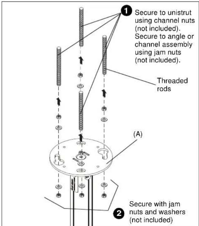
Figure 6
Installing to a Solid Concrete Ceiling Structure

WARNING: The CPA116 is designed to be mounted to a concrete ceiling with a minimum thickness of 8" and a maximum drywall covering of 5/8 (1.6cm).

WARNING: Fischer UX10 or AF8 anchors (not included) must be installed into structurally sound solid concrete. Installation into hollow concrete block, mortar, or concrete that exhibits cracking, spalling, or other defects may result in failure of anchor and serious personal injury or damage to equipment.
- Using ceiling plate (A) as a template, mark locations of four pilot holes on ceiling.
- Drill pilot holes at marked locations. If using UX10 anchors, pilot hole diameter will be 3/8". If using AF8 anchors, pilot hole diameter will be 5/16".
- Install four UX10 or AF8 anchors into four drilled holes. (See Figure 7)
- Loosely install two 5 / 16'' x 2 3/4" bolts (not provided) through two 5 / 16'' flat washers (not provided) into opposite anchors. (See Figure 7)
- Place ceiling plate (A) up to ceiling and turn until bolts hold plate up in position. (See Figure 7)
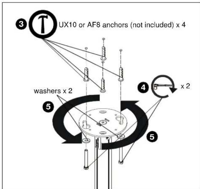
Figure 7
- Install two 5 / 16^ × 23 / 4^ bolts (not included) through two 5 / 16^ flat washers (not included) through holes on ceiling plate A and into anchors. (See Figure 8)
- Tighten all four bolts to secure plate to ceiling. (See Figure 8)
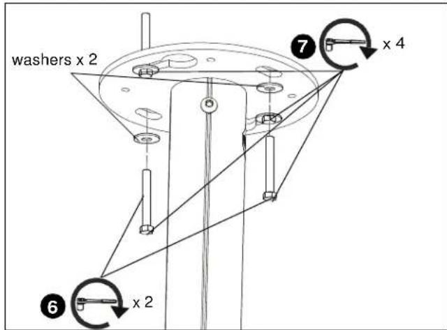
Figure 8
Installing Ceiling Plate Cover
- Maneuver ceiling plate cover (B) so that it is able to wrap around extension column. (See Figure 9)
- Wrap ceiling plate cover (B) around extension column. (See Figure 9)
- Use two M6 x 6mm button head cap screws (E) to secure ceiling plate cover (B) to CPA116 plate (A). (See Figure 9).
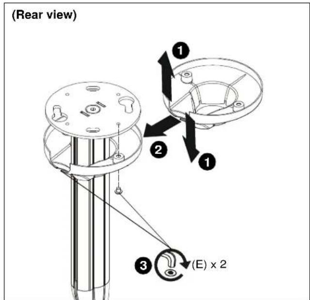
Figure 9
- Complete installation following column extension installation instructions.
CLAUSES DE NON-RESPONSABILITÉ
DIMENSIONS:POUCES [MILLIMETRES]
OUTILS NÉCESSAIRES À L'INSTALLATION