16701 - Drill MILWAUKEE - Free user manual and instructions
Find the device manual for free 16701 MILWAUKEE in PDF.
User questions about 16701 MILWAUKEE
0 question about this device. Answer the ones you know or ask your own.
Ask a new question about this device
Download the instructions for your Drill in PDF format for free! Find your manual 16701 - MILWAUKEE and take your electronic device back in hand. On this page are published all the documents necessary for the use of your device. 16701 by MILWAUKEE.
USER MANUAL 16701 MILWAUKEE
WARNING READ ALL SAFETY WARNINGS AND ALL INSTRUCTIONS. Failure to follow the warnings and instructions may result in electric shock, fire and/or serious injury. Save all warnings and instructions for future reference. The term "power tool" in the warnings refers to your mains-operated (cored) power tool or battery-operated (cordless) power tool.
WORK AREA SAFETY
- Keep work area clean and well lit. Cluttered or dark areas invite accidents.
- Do not operate power tools in explosive atmospheres, such as in the presence of a ammable liquids, gases or dust. Power tools create sparks which may ignite the dust or fumes.
- Keep children and bystanders away while operating a power tool. Distractions can cause you to lose control.
ELECTRICAL SAFETY
- Power tool plugs must match the outlet. Never modify the plug in any way. Do not use any adapter plugs with earthed (grounded) power tools. Unmodified plugs and matching outlets will reduce risk of electric shock.
- Avoid body contact with earthed or grounded surfaces such as pipes, radiators, ranges and refrigerators. There is an increased risk of electric shock if your body is earthed or grounded.
- Do not expose power tools to rain or wet conditions. Water entering a power tool will increase the risk of electric shock.
- Do not abuse the cord. Never use the cord for carrying, pulling or unplugging the power tool. Keep cord away from heat, oil, sharp edges or moving parts. Damaged or entangled cords increase the risk of electric shock.
- When operating a power tool outdoors, use an extension cord suitable for outdoor use. Use of a cord suitable for outdoor use reduces the risk of electric shock.
- If operating a power tool in a damp location is unavoidable, use a ground fault circuit interrupter (GFCI) protected supply. Use of an GFCI reduces the risk of electric shock.
PERSONAL SAFETY
- Stay alert, watch what you are doing and use common sense when operating a power tool. Do not use a power tool while you are tired or under the influence of drugs, alcohol or medication. A moment of inattention while operating power tools may result in serious personal injury.
- Use personal protective equipment. Always wear eye protection. Protective equipment such as dust mask, non-skied safety shoes, hard hat, or hearing protection used for appropriate conditions will reduce personal injuries.
-
Prevent unintentional startling. Ensure the switch is In the off-position before connecting to power source and/or battery pack, picking up or carrying the tool. Carrying power tools with your finger on the switch or energising power tools that have the switch on invites accidents.
-
Remove any adjusting key or wrench before turning the power tool on. A wrench or a key left attached to a rotating part of the power tool may result in personal injury.
- Do not overreach. Keep proper footing and balance at all times. This enables better control of the power tool in unexpected situations.
- Dress properly. Do not wear loose clothing or jewellery. Keep your hair, clothing and gloves away from moving parts. Loose clothes, jewellery or long hair can be caught in moving parts.
- If devices are provided for the connection of dust extraction and collection facilities, ensure these are connected and properly used. Use of dust collection can reduce dust-related hazards.
POWER TOOL USE AND CARE
- Do not force the power tool. Use the correct power tool for your application. The correct power tool will do the job better and safer at the rate for which it was designed.
- Do not use the power tool if the switch does not turn it on and off. Any power tool that cannot be controlled with the switch is dangerous and must be repaired.
- Disconnect the plug from the power source and/or the battery pack from the power tool before making any adjustments, changing accessories, or storing power tools. Such preventive safety measures reduce the risk of starting the power tool accidentally.
- Store idle power tools out of the reach of children and do not allow persons unfamiliar with the power tool or these instructions to operate the power tool. Power tools are dangerous in the hands of untrained users.
- Maintain power tools. Check for misalignment or binding of moving parts, breakage of parts and any other condition that may affect the power tool's operation. If damaged, have the power tool repaired before use. Many accidents are caused by poorly maintained power tools.
- Keep cutting tools sharp and clean. Properly maintained cutting tools with sharp cutting edges are less likely to bind and are easier to control.
- Use the power tool, accessories and tool bits etc. In accordance with these Instructions, taking into account the working conditions and the work to be performed. Use of the power tool for operations different from those intended could result in a hazardous situation.
SERVICE
- Have your power tool serviced by a qualified repair person using only identical replacement parts. This will ensure that the safety of the power tool is maintained.
SPECIFIC SAFETY RULES
- Use auxiliary handle(s), if supplied with the tool. Loss of control can cause personal injury.
- Hold power tool by insulated gripping surfaces, when performing an operation where the cutting accessory may contact hidden wiring or its own cord. Cutting accessory contacting a "live" wire may make exposed metal parts of the power tool "live" and could give the operator an electric shock.
- Maintain labels and nameplates. These carry important information. If unreadable or missing, contact a MILWAUKEE service facility for a free replacement.
WARNING Some dust created by power sanding, sawing, grinding, drilling, and other construction activities contains chemicals known to cause cancer, birth defects or other reproductive harm. Some examples of these chemicals are: - lead from lead-based paint
- crystalline silica from bricks and cement and other masonry products, and
- arsenic and chromium from chemically-treated lumber.
Your risk from these exposures varies, depending on how often you do this type of work. To reduce your exposure to these chemicals: work in a well ventilated area, and work with approved safety equipment, such as those dust masks that are specially designed to fit later out microscopic particles.
SYMBOLOGY
| A | Amps |
| V | Volts |
| ~ | Alternating Current Only |
| n0XXXXmin.1 | No Load Revolutions per Minute (RPM) |
| cULUS | Underwriters Laboratories, Inc. United States and Canada |
| NOM·ANCE | Mexican Approvals Marking |
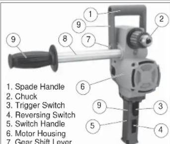
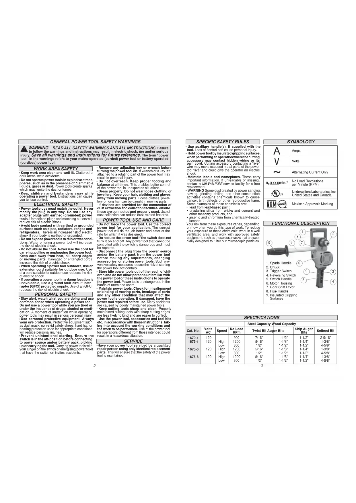
FUNCTIONAL DESCRIPTION
- Pipe Handle
- Insulated Gripping Surfaces
SPECIFICATIONS
| Steel Capacity Wood Capacity | ||||||
| Cat. No. | Volts AC | Speed | No Load RPlm | Twist Bit Auger Bits | Ship Auger Bits | Selfeed Bit |
| 1670-1 | 120 | - | 900 | 7/16" | 1-1/2" | 1-1/2" |
| 1675-1 | 120 | High | 1200 | 5/16" | 1-1/8" | 1-1/4" |
| Low | 300 | 1/2" | 1-1/2" | 1-1/2" | ||
| 1675-6 | 120 | High | 1200 | 5/16" | 1-1/8" | 1-1/4" |
| Low | 300 | 1/2" | 1-1/2" | 1-1/2" | ||
| 1676-6 | 120 | High | 1200 | 5/16" | 1-1/8" | 1-1/4" |
| Low | 300 | 1/2" | 1-1/2" | 1-1/2" | ||
GROUNDING
WARNING Improperly connecting the grounding wire can result in the risk of electric shock. Check with a qualita edlectrician If you are in doubt as to whether the outlet is properly grounded. Do not modify the plug provided with the tool. Never remove the grounding prong from the plug. Do not use the tool if the cord or plug is damaged. If damaged, have it repaired by a MIL WAUKEE service facility before use. If the plug will not fit the outlet, have a proper outlet installed by a qualita edlectrician.
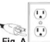
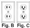
Grounded Tools: Tools with Three Prong Plugs Tools marked "Grounding Required" have a three wire cord and three prong grounding plug. The plug must be connected to a properly grounded outlet (See Figure A). If the tool should electrically malfunction or break down, grounding provides a low resistance path to carry electricity away from the user, reducing the risk of electric shock.
The grounding prong in the plug is connected through the green wire inside the cord to the grounding system in the tool. The green wire in the cord must be the only wire connected to the tool's grounding system and must never be attached to an electrically "live" terminal.
Your tool must be plugged into an appropriate outlet, properly installed and grounded in accordance with all codes and ordinances. The plug and outlet should look like those in Figure A.
Double Insulated Tools: Tools with Two Prong Plugs
Tools marked "Double Insulated" do not require grounding. They have a special double insulation system which salisi es OSHA requirements and complies with the applicable standards of
Underwriters Laboratories, Inc., the Canadian Standard Association and the National Electrical Code. Double Insulated tools may be used in either of the 120 volt outlets shown in Figures B and C.
EXTENSION CORDS
Grounded tools require a three wire extension cord. Double insulated tools can use either a two or three wire extension cord. As the distance from the supply outlet increases, you must use a heavier gauge extension cord. Using extension cords with inadequately sized wire causes a serious drop in voltage, resulting in loss of power and possible tool damage. Refer to the table shown to determine the required minimum wire size.
The smaller the gauge number of the wire, the greater the capacity of the cord. For example, a 14 gauge cord can carry a higher current than a 16 gauge cord. When using more than one extension cord to make up the total length, be sure each cord contains at least the minimum wire size required. If you are using one extension cord for more than one tool, add the nameplate amperes and use the sum to determine the required minimum wire size.
Guidelines for Using Extension Cords
If you are using an extension cord outdoors, be sure it is marked with the suf: × "W-A" ("W" in Canada) to indicate that it is acceptable for outdoor use.
- Be sure your extension cord is properly wired and in good electrical condition. Always replace a damaged extension cord or have it repaired by a qualified person before using it.
- Protect your extension cords from sharp objects, excessive heat and damp or wet areas.
| Recommended Minimum Wire Gauge For Extension Cords* | |||||
| Extension Cord Length | |||||
| Nameplate Amperes | 25' | 75' | 100' | 150' | |
| 0 - 2.0 | 18 | 18 | 18 | 18 | 16 |
| 2.1 - 3.4 | 18 | 18 | 18 | 16 | 14 |
| 3.5 - 5.0 | 18 | 18 | 16 | 14 | 12 |
| 5.1 - 7.0 | 18 | 16 | 14 | 12 | 12 |
| 7.1 - 12.0 | 16 | 14 | 12 | 10 | |
| 12.1 - 16.0 | 14 | 12 | 10 | ||
| 16.1 - 20.0 | 12 | 10 | |||
Based on limiting the line voltage drop to 12 ve volts at 150% of the rated amperes.
READ AND SAVE ALL INSTRUCTIONS FOR FUTURE USE.
ASSEMBLY
WARNING To reduce the risk of Injury, always unplug tool before attaching or removing accessories or making adjustments. Use only specia cally recommended accessories. Others may be hazardous.
Installing Bits into Keyed Chucks 1. Unplug tool.
- Open the chuck jaws wide enough to insert the bit. Be sure the bit shank and chuck jaws are clean. Dirt particles may prevent the bit from lining up properly.
- Insert the bit into the chuck. Center the bit in the chuck jaws and lift it about 1 / 16^ off of the bottom. Tighten the chuck jaws by hand to align the bit.
- Place the chuck key in each of the three holes in the chuck, turning it clockwise. Tighten securely.
- To remove the bit, insert the chuck key into one of the holes in the chuck and turn it counterclockwise.
Bit Selection
- Use sharp bits. Sharp bits are less likely to bind when drilling.
- Use the proper bit for the job. There are many types of bits designed for specific purposes. Check the information on the bit's packaging for proper usage.
- Do not use bits larger than the rated capacity of the drill. Gear damage or motor overload may result.
Pipe Handle
The pipe handle may be used on either side of the tool. Thread pipe handle into one of the threaded holes in the motor housing.
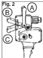
Spade Handle
The spade handle can be attached to the tool in three positions. Remove the hex head screws which secure the handle. Remove the handle and move it to the desired position. To mount the handle in position C, it is necessary to reverse the mounting holes by turning the handle around.
OPERATION
WARNING To reduce the risk of Injury, wear safety goggles or glasses with slide shields.
WARNING To reduce the risk of personal injury when drilling, hold tool by insulated gripping surfaces when performing an operation where the cutting tool may contact hidden wiring or its own cord. Contact with a "live" wire will make exposed metal parts of the tool "live" and shock the operator.
WARNING When drilling with a single speed drill or in HI with a two speed drill, always hold the drill securely using the pipe handle, or brace the drill against a solid xed object in preparation for a sudden reaction. When drilling in LO with a two speed drill, always brace the drill against a solid xed object in preparation for a sudden reaction. When drilling, never use your body to brace drill.
Never put your hands (or other body parts) between the part of the drill being braced and the object it is being braced against. Hands (or other body parts) that are in the path of the reaction can be pinched, crushed and broken.
Bit binding
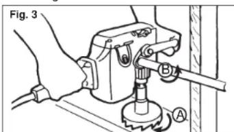
If the bit binds, the drill will suddenly react in the opposite direction of the rotation of the bit. Figure 3 shows the path of reaction (B) if the drill bit binds while being driven in forward (A). The operator should reduce the chances of a sudden reaction by following the instructions listed below.
The operator should also prepare for a sudden reaction by holding securely using the pipe handle or bracing against a solid xed object.
To reduce the chance of blt blinding
-
Use sharp bits. Sharp bits are less likely to bind when drilling.
-
Use the proper bit for the job. There are many types of bits designed for specific purposes.
-
Use the proper speed for the size bit. Larger bits should be run at the lower speed. Driving larger bits at high speeds will increase the chance of the bit binding and increase the chance of reaction.
-
Avoid drilling warped, wet, knotty, and or pitchy material if possible.
-
Avoid drilling in material that you suspect contains hidden nails or other things that may cause the bit to bind.
The direction of reaction is always opposite of the direction of bit rotation.
Reaction is even more likely to occur when enlarging already existing holes and at the point when the bit breaks through the other side of the material.
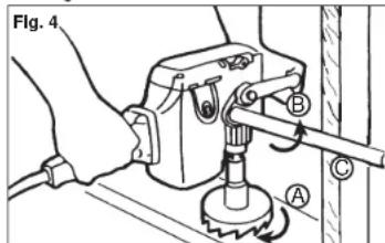
Bracing for forward rotation
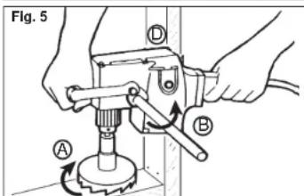
When drilling in forward, the bit will rotate in a clockwise direction. If the bit binds in the hole, the bit will come to a sudden stop and drill will suddenly react in a counterclockwise direction.
Figures 4 and 5 show examples of a Hole Hawg properly braced for forward rotation.
A.Forward (clockwise) rotation
B. Reaction
C. Brace drill with pipe handle here
D. Brace drill with motor housing here
If the bit binds, the pipe handle or the motor housing braced against the stud will hold the drill in position.
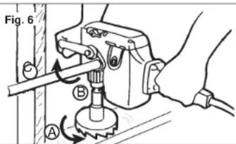
Bracing for reverse rotation
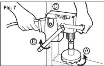
When drilling in reverse, the bit will rotate in a counterclockwise direction. If the bit binds in the hole, the bit will come to a sudden stop and the drill will suddenly react in a clockwise direction. Figures 6 and 7 show examples of the Hole Hawg properly braced for reverse rotation.
A. Reverse (counterclockwise) rotation
B. Reaction
C. Brace drill with pipe handle here
D. Brace drill with motor housing here
If the bit binds, the pipe handle or the motor housing braced against the stud will hold the drill in position.
Reversing
A reversing switch is located below the trigger switch for removal of bits from holes. Permit the motor to come to a complete stop before reversing. Reversing the tool with the gears in motion may cause severe damage. When removing self-fed bits from partially drilled holes, a rick of the trigger switch will free the threaded pilot screw. When the threads are loose, lift the bit from the workpiece with the motor stopped.
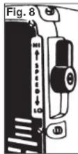
Shifting Speeds
Cat. No. 1675-1 has a gear shift lever on the right side of the gear case.
The high setting (1200 RPM HI) is the low torque setting and is designed for driving Selfeed bits 1 - 3 / 8^ in diameter and smaller. The low setting (300 RPM LO) is the high torque setting and is designed for driving Selfeed bits 1 - 1 / 2^ in diameter and larger.
Always turn off the switch and shift while the tool is coasting to
a stop. Never shift the drill while it is moving at full speed, when it is under load, or when it is stopped.

WARNING To reduce the risk of electric shock, check work area for hidden pipes and pipes before drilling or driving screws.
Drilling
Before drilling, clamp down the material securely. A poorly secured piece of material may result in personal injury or inaccurate drilling. When drilling in light gauge metal or wood, use a wooden block to back up the material to prevent damage to the workpiece.
Mark the center of the hole to be drilled with a center punch to give the bit a start and to prevent it from "walking." Lubricate the drill bit with cutting oil when drilling iron or steel. Use a coolant when drilling nonferrous metals such as copper, brass or aluminum.
To start a selffeed bit, run the threaded feed screw into the work by licking the trigger switch, permitting the bit to coast until the teeth contact the work surface. Align the bit properly before proceeding. This will reduce cocking and jamming when starting. To reduce jamming on breakthrough, decrease the drilling pressure when the feed screw point breaks through the workpiece. Proceed with steady, even pressure.

WARNING To reduce the risk of injury, pays wear eye protection.
Chuck Removal
To remove the chuck from the drill:
- Unplug tool
- Fully open the chuck jaws
- Remove the left-handed thread screw from inside the chuck by turning it clockwise.
- Pull the chuck off of the spindle.
NOTE: If the chuck does not pull off of the spindle easily, tap the side of the chuck with a hammer to loosen it. If this doesn't work, contact a MILWAUKEE service center.
ACCESSIONS

WARNING To reduce the risk of injury, ways unplug the tool before attaching or moving accessories. Use only speciably commended accessories. Others may be hazardous.
For a complete listing of accessories refer to your MILWAUKEE Electric Tool catalog or go on-line to www.milwaukeotool.com. To obtain a catalog, contact your local distributor or a service center.
MAINTENANCE

WARNING To reduce the risk of Injury, it says unplug your tool before performing a maintenance. Never disassemble the tool any to do any rewiring on the tool's electrical system. Contact a MILWAUKEE service facility for ALL repairs.
Maintaining Tools
Keep your tool in good repair by adopting a regular maintenance program. Before use, examine the general condition of your tool. Inspect guards, switches, tool cord set and extension cord for damage. Check for loose screws, misalignment, binding of moving parts, improper mounting, broken parts and any other condition that may affect its safe operation. If abnormal noise or vibration occurs, turn the tool off immediately and have the problem corrected before further use. Do not use a damaged tool. Tag damaged tools "DO NOT USE" until repaired (see "Repairs").
Under normal conditions, reubligation is not necessary until the motor brushes need to be replaced. After six months to one year, depending on use, return your tool to the nearest MIL WALU/KEE service facility for the following:
Lubrication
- Brush inspection and replacement
- Mechanical inspection and cleaning (gears, spindles, bearings, housing, etc.)
- Electrical inspection (switch, cord, armature, etc.)
- Testing to assure proper mechanical and electrical operation

WARNING To reduce the risk of injury, a strict shock and damage to the tool, never interfere your tool In liquid or allow a liquid to blow inside the tool.
Cleaning
Clean dust and debris from vents. Keep the tool handles clean, dry and free of oil or grease. Use only mild soap and a damp cloth to clean your tool since certain cleaning agents and solvents are harmful to plastics and other insulated parts. Some of these include: gasoline, tupentine, lacquer thinner, paint thinner, chlorinated cleaning solvents, ammonia and household detergents containing ammonia. Never use ammable or combustible solvents around tools.
Repairs
If your tool is damaged, return the entire tool to the nearest service center.
LIMITED WARRANTY - USA AND CANADA
Every MILWAUKEE power tool (including cordless product - tool, battery pack(s) - see separate & distinct CORDLESS BATTERY PACK LIMITED WARRANTY statements & battery charger and Work Lights) is warranted to the original purchaser only to be free from defects in material and workmanship. Subject to certain exceptions, MILWAUKEE will repair or replace any part on an electric power tool which, after examination, is determined by MILWAUKEE to be defective in material or workmanship for a period of five (5) years after the date of purchase unless otherwise noted. Return of the power tool to a MILWAUKEE factory Service Center location or MILWAUKEE Authorized Service Station, freight prepaid and Insured, is required. A copy of the proof of purchase should be included with the return product. This warranty does not apply to damage that MILWAUKEE determines to be from repairs made or attempted by anyone other than MILWAUKEE authorized personnel, misuse, alterations, abuse, normal wear and tear, lack of maintenance, or accidents.
The warranty period for, Job Site Radios, M12TM Power Port, M18TM Power Source, and Trade Titan™ Industrial Work Carts is one (1) year from the date of the purchase. The warranty period for a LED Work Light and LED Upgrade Bulb is a limited LIFETIME WARRANTY to the original purchaser only, if during normal use the LED bulb fails the Work Light or Upgrade Bulb will be replaced free of charge.
*This warranty does not cover Air Nails & Stapler, Airless Paint Sprayer, Cordless Battery Pack, Gasoline Driven Portable Power Generators, Hand Tools, Hoist - Electric, Lever & Hand Chain, M12TM Heated Jackets, Reconditioned product and Test & Measurement products. There are separate and distinct warranties available for these products.
Warranty Registration is not necessary to obtain the applicable warranty on a MILWAUKEE power tool product. The manufacturing date of the product will be used to determine the warranty period if no proof of purchase is provided at the time warranty service is requested.
ACCEPTANCE OF THE EXCLUSIVE REPAIR AND REPLACEMENT REMEDIES DESCRIBED HEREIN IS A CONDITION OF THE CONTRACT FOR THE PURCHASE OF EVERY MILWAUKEE PRODUCT. IF YOU DO NOT AGREE TO THIS CONDITION, YOU SHOULD NOT PURCHASE THE PRODUCT. IN NO EVENT SHALL MILWAUKEE BE LIABLE FOR ANY INCIDENTAL SPECIAL CONSEQUENTIALLY OR PUNUTIVE DAMAGES, OR FOR ANY COSTS, ATTORNEY FEES, EXPENSES, LOSSES OR DELAYS ALGEGED TO BE AS A CONSEQUENCE OF ANY DAMAGE TO, FAILURE OF, OR DEFECT IN ANY PRODUCT INCLUDING, BUT NOT LIMITED TO, ANY CLAIMS FOR LOSS OF PROFITS. SOME STATES DO NOT ALLOW THE EXCLUSION OR LIMITATION OF INCIDENTAL OR CONSEQUENTIALL DAMAGES, SO THE ABOVE LIMITATION OR EXCLUSION MAY NOT APPLY TO YOU. THIS WARRANTY IS EXCLUSIVE AND IN LIEUDE OF ALL OTHER EXPRESS WARRANTYMENTS, WRITTEN OR ORAL. TO THE EXTENT PERMITTED BY LAW, MILWAUKEE DISCLAIMS ANY IMPLIED WARRANTYES, INCLUDING WITHOUT LIMITATION ANY IMPLIED WARRANTY OF MERCHANTIBILITY OR FITNESS FOR A PARTICULAR USE OR PURPOSE; TO THE EXTENT SUCH WARRANTYER IS NOT PERMITTED BY LAW, SUCH IMPLIED WARRANTYES ARE LIMITED TO THE DURATION OF THE APPLICABLE EXPRESS WARRANTY AS DESCRIBED ABOVE. SOME STATES DO NOT ALLOW LIMITATIONS ON HOW LONG AN IMPLIED WARRANTY LASTS, SO THE ABOVE LIMITATION MAY NOT APPLY TO YOU, THIS WARRANTY GIVES YOU SPECIFIC LEGAL RIGHTS, AND YOU MAY ALSO HAVE OTHER RIGHTS WHICH VARY FROM STATE TO STATE. This warranty applies to product sold in the U.S.A. and Canada only.
Please consult the 'Service Center Search' in the Parts & Service section of MILWAUKEE's website www.milwaukeetool.com or call 1.800.SAWDUST (1,800.729.3878) to locate your nearest service facility for warranty and non-warranty service on a Milwaukee electric power tool.
LIMITED WARRANTY - MEXICO, CENTRAL AMERICA AND CARIBBEAN
TECHTRONIC INDUSTRIES' warranty is for 5 year since the original purchase date.
This warranty card covers any defect in material and workmanship on this Power Tool.
To make this warranty valid, present this warranty card, sealed/stamped by the distributor or store where you purchased the product, to the Authorized Service Center (ASC). Or, if this card has not been sealed/stamped, present the original card and the product.
Call toll-free 1 800 832 1949 to nd the nearest ASC, for service, parts, accessories or components.
Procedure to make this warranty valid
Take the product to the ASC, along with the warranty card sealed/stamped by the distributor or store where you purchase it. If you want a full set of components or component will be replaced without cost for you. We will cover all freight costs relative with this warranty process.
Exceptions
This warranty is not valid in the following situations:
a) When the product is used in a different manners from the end-user guide or instruction manual.
b) When the conditions of use are not normal.
c) When the product was modified or repaired by people not authorized by TECHTRONIC INDUSTRIES.
Note: If cord set is damaged, it should be replaced by an Authorized Service Center to avoid electric risks.
SERVICE AND ATTENTION CENTER
Model:Presidente Mazarik 29 Piso 7,11570 Chapultenec Morales
Miguel Hidalgo, Distrito Federal, Mexico
Date of Purchase:3547
Prrnreerreeeeeee
H
TECHTRONIC INDUSTRIES MEXICO.,S.A,DE C.V.
Av Presidente Mazarik 29 Piso 7,11570 Chapultepec Morales
Miguel Hidalgo, Distrito Federal, Mexico
REGLES DE SECURITE GENERALES RELATIVES AUX UTILS ELECTRIQUES
UNITED STATES MIL WUAKEE Service
MIL.WALUKEE prides itself in producing a premium quality product that is NOTING BUT HEAVY DUTY. Your satisfaction with our products is very important to usl If you encounter any problems with the operation of this tool, or you would like to locate the factory Service/Sales Support Branch or authorized service station nearest you, please call... Additionally, we have a nationwide network of authorized Distributors ready to assist you with your tool and accessory needs. Check your "Yellow Pages" phone directory under "Tools-Electric" for the names & addresses of those nearest you or see the Where To Buy' section of our website.
1-800-SAWDUST
(1.800.729.3878)
Monday-Friday
7:00AM-6:30
Central Time
or visit our website at www.milwaukeetoole.com
For service information, use the Service Center Search icon found in the 'Parts & Service' section.
Contact: our Corporate After Sales Service Technical Support about
Technical Support about .. Technical Questions
Technical Questions Service/Benign Over
Warranty
call: 1-800-SAWDUST
fax:1.800.638.9582
email:metproductsupport@milwaukeetool.com
Register your tool online at
www.milwaukeeetoole.com and...
- receive important noti i cations regarding
your purchase - ensure that your tool is protected under the warranty
become a HEAVY DUTY club member
MEXICO-Soporte de
CENTRO DE ATENCLON A CLIENTES
Presidente Mazarik 29 Piso
11570 Chapultepec Morales
Miguel Hidalgo, Distrito Federal, Mexico
Telefon 52 55 4160-3547
e-mail: servicio@ttic
MILWAUKEE ELECTRIC TOOL CORPORATION
13135 West Lisbon Road • Brookfield, Wisconsin, U.S.A. 53005
58-14-1782d14
10/13 Printed in China
961075017-05()
CANADA - Service MILWAUKEE
MILWAUKKEE prides itself in producing a premium quality product that is NOTHING BUT HEAVY DUTY. Your satisfaction with our products is very important to us!
If you encounter any problems with the operation of this tool, or you would like to locate the factory Service/Sales Support Branch or authorized service station nearest you, please call...
1,800,268,4015
Monday-Friday 7:00-4:30 CST
fax:866.285.9049
Milwaukee Electric Tool (Canada) Ltd. 2004
140 Persian Court,Unit 418211NYAvenue NW Vaughan, ON L4K 3L8Edmonton, AB T5S 2P2
Additionally, we have a nationwide network of authorized Distributors ready to assist you with your tool and accessory needs. Call 1.800.268.4015 to find the names and addresses of the closest re tailers or consult "Where to buy" on our Web site