ROG STRIX Z790A GAMING WIFI II - Wall socket ASUS - Free user manual and instructions
Find the device manual for free ROG STRIX Z790A GAMING WIFI II ASUS in PDF.
| Product Type | Motherboard |
| Brand | ASUS |
| Model | ROG STRIX Z790-A GAMING WIFI II |
| Form Factor | ATX |
| Processor Socket | LGA1700 |
| Chipset | Intel Z790 |
| Supported Memory | DDR5, 4 slots, max 128 GB |
| PCIe Slots | 1x PCIe 5.0 x16, 1x PCIe 4.0 x16, 2x PCIe 3.0 x1 |
| Storage | 4x SATA 6 Gb/s, 4x M.2 (PCIe 4.0) |
| Network Connectivity | Wi-Fi 6E, Bluetooth 5.3, Ethernet 2.5 Gb/s |
| Audio | Realtek ALC4080, 7.1 channels |
| USB Ports | USB 3.2 Gen2x2 Type-C, USB 3.2 Gen2, USB 2.0 |
| Power Supply | ATX 24-pin, EPS 8+4 pin connectors |
| Dimensions | 30.5 cm x 24.4 cm |
| Weight | Approximately 1.5 kg |
| Care and Cleaning | Clean with a soft dry cloth; avoid liquids |
| Safety | Compliant with CE, FCC standards; indoor use for certain bands |
| Spare Parts and Repairability | Parts available through ASUS service; repairability index not disclosed |
Frequently Asked Questions - ROG STRIX Z790A GAMING WIFI II ASUS
User questions about ROG STRIX Z790A GAMING WIFI II ASUS
0 question about this device. Answer the ones you know or ask your own.
Ask a new question about this device
Download the instructions for your Wall socket in PDF format for free! Find your manual ROG STRIX Z790A GAMING WIFI II - ASUS and take your electronic device back in hand. On this page are published all the documents necessary for the use of your device. ROG STRIX Z790A GAMING WIFI II by ASUS.
USER MANUAL ROG STRIX Z790A GAMING WIFI II ASUS
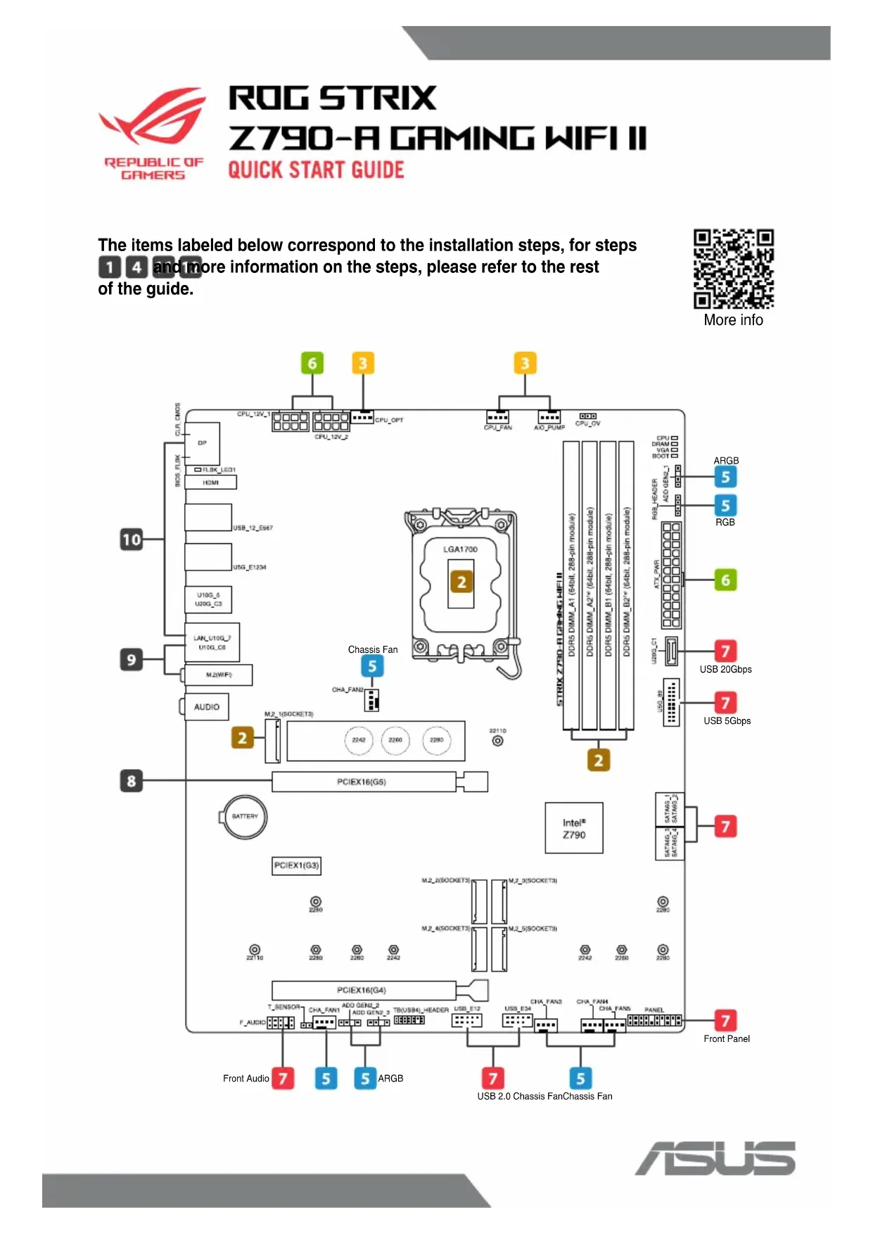
The items labeled below correspond to the installation steps, for steps 1 and more information on the steps, please refer to the rest of the guide.

More info

text_image
CLR CMOS DIP FLBK_LED1 HDMI USB_12_E567 USG_E1234 U10G_5 U20G_C3 LAN_U10G_7 U10G_C6 M.2(WiF) AUDIO 8 10 9 Chassis Fan 5 CHA_FAN2 2 M.2_1(SOCKET3) 2242 2260 2280 22110 PCIEX16(G5) BATTERY PCIEX1(G3) 2290 22110 PCIEX16(G4) T_SENSOR CHA_FAN1 ADD GEN2_3 TB(USB4)HEADER USB_E12 F_AUDIO 6 3 3 CPU_12V_1 CPU_12V_2 CPU_OPT CPU_FAN AIO_PUMP CPU_OV STRIX Z790 - B DRINK HIFI II DDR5 DIMM_A1 (64bit, 288-pin module) DDR5 DIMM_A2" (64bit, 288-pin module) DDR5 DIMM_B1 (64bit, 288-pin module) DDR5 DIMM_B2" (64bit, 288-pin module) CPU C DRAM VGA BOOT RGB_HEADER ADD GEN2_1 ATX_PWR USB_C1 U20G_8 USB_9 USB_10 USB_11 USB_12 USB_13 USB_14 USB_15 USB_16 USB_17 USB_18 USB_19 USB_20 USB_21 USB_22 USB_23 USB_24 USB_25 USB_26 USB_27 USB_28 USB_29 USB_30 USB_31 USB_32 USB_33 USB_34 USB_35 USB_36 USB_37 USB_38 USB_39 USB_40 USB_41 USB_42 USB_43 USB_44 USB_45 USB_46 USB_47 USB_48 USB_49 USB_50 USB_51 USB_52 USB_53 USB_54 USB_55 USB_56 USB_57 USB_58 USB_59 USB_60 USB_61 USB_62 USB_63 USB_64 USB_65 USB_66 USB_67 USB_68 USB_69 USB_70 USB_71 USB_72 USB_73 USB_74 USB_75 USB_76 USB_77 USB_78 USB_79 USB_80 INTel® Z790 SATAW3_SATAW3_D SATAW3_SATAW3_D SATAW3_SATAW3_D SATAW3_SATAW3_D Front Audio 7 5 5 ARGB 7 5 Front PanelUSB 2.0 Chassis FanChassis Fan
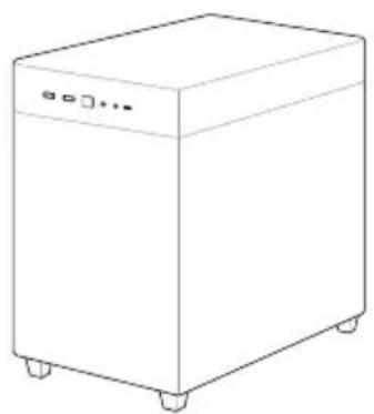
1 Prepare the components
natural_image
Line drawing of a simple rectangular industrial machine with wheels and a control panel (no text or symbols)Chassis

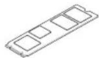
natural_image
Two technical line drawings of rectangular components, one with a rounded square and one with a flat rectangular base (no text or symbols)CPU Memory M.2 SSD

natural_image
Technical line drawings of a mechanical component with two views: top shows a fan-like structure, bottom shows a cylindrical housing with a tool inserted (no text or symbols)CPU Cooler

SATA device

Power supply unit Graphics card
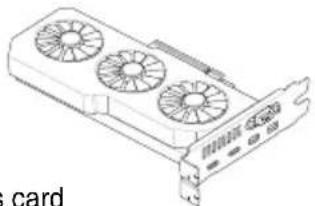
natural_image
Illustration of a card with three fans and a card slot (no text or symbols)NOTE: The components listed above are recommendations, please prepare components according to your needs.
2 Install key components
- Install the CPU
Please scan for more information on CPU installation steps.
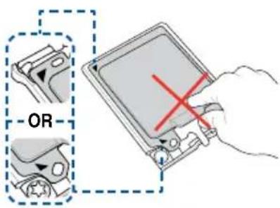
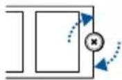
text_image
-OR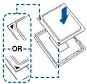
text_image
OR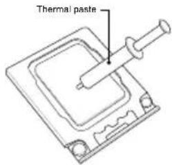
text_image
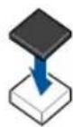
Thermal paste
natural_image
Cartoon astronaut character in red spacesuit with a black face and red earbuds, giving a thumbs-up (no text or symbols)NOTE: Do not remove the PnP cap before the CPU is properly installed.
Please refer to the manual(s) for more information: Motherboard
• Install the Memory
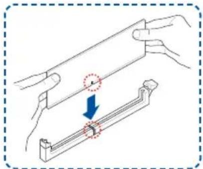
natural_image
Illustration of hands holding a metal rod with a blue arrow indicating compression or dislocation (no text or symbols present)
text_image
DIMM_A2¹⁶ DIMM_A2¹⁸ DIMM_B2¹⁸ DIMM_A1 DIMM_A2¹⁸ DIMM_B1 DIMM_B2¹⁸NOTE: Please refer to the manual(s) for more information: Motherboard
• Install the M.2 SSD

text_image
Remove
Remember to rotate the M.2 Q-latch or secure the screw properly.

OPTIONAL
Install the bundled rubber for M.2 when installing a single sided M.2 module.
NOTE: Please refer to the manual(s) for more information:
Motherboard
3 Install the cooling system
- Air Cooler
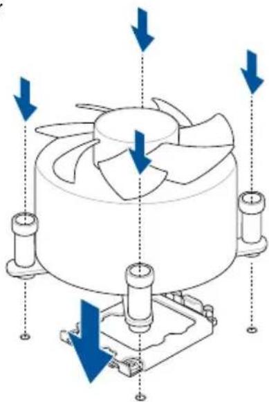
natural_image
Technical diagram of a fan or impeller assembly with directional arrows indicating motion (no text or symbols present)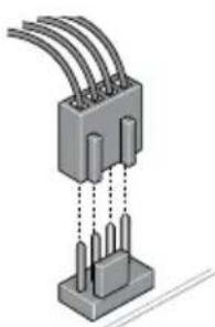
natural_image
Isometric illustration of a 3-pin electrical connector with multiple leads and pins (no text or symbols)CPU_FAN / CPU_OPT
OR
- AIO Cooler
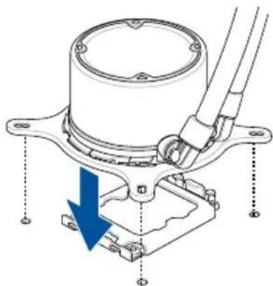
natural_image
Technical diagram of a mechanical assembly with a blue arrow indicating a downward motion (no text or symbols present)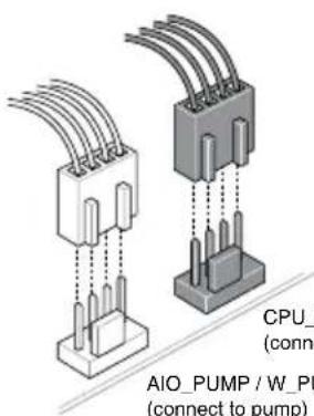
text_image
CPU_ (connect AIO_PUMP / W_PUMP (connect to pump)CPU_FAN / CPU_OPT (connect to radiator)
AIO_PUMP / W_PUMP (connect to pump)
NOTE: Please refer to these manual(s) for more information:
Cooler Chassis
4 Install the motherboard into the chassis
A
For non pre-mounted I/O shield models only.
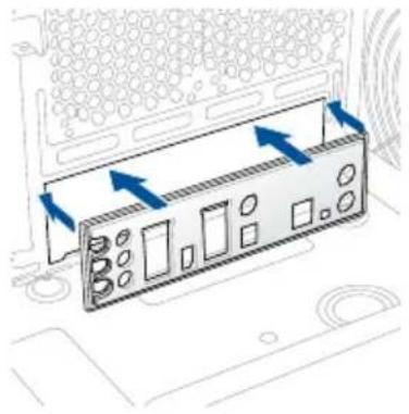
natural_image
Diagram of a computer monitor with directional arrows indicating ports or connections (no text or symbols present)B

natural_image
Diagram of a computer motherboard with a fan and heatsink, showing a blue arrow indicating a process or operation (no text or symbols present)C
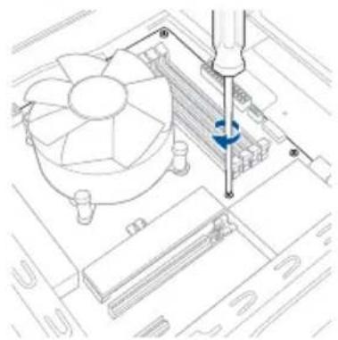
natural_image
Technical line drawing of a computer motherboard with a screwdriver inserted, showing fan and drive components (no text or symbols)NOTE: Please refer to the manual(s) for more information: Motherboard Chassis
Connect cables from Chassis
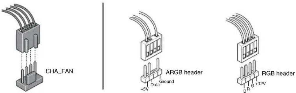
5 Connect to chassis fan and ARGB/RGB headers
text_image
CHA_FAN +5V Data Ground ARGB header RGB header B R G +12VNOTE: Please refer to the manual(s) for more information: Motherboard Chassis Fan
6 Install and connect the power supply unit (PSU)
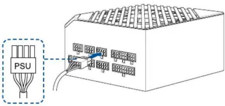
text_image
PSU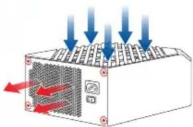
natural_image
Diagram of a computer power supply unit with cooling fan and red arrows indicating airflow or heat transfer (no text or symbols)Make sure the PSU is secured to the chassis using screws, and that the chassis has proper airflow.
NOTE: Please refer to the manual(s) for more information: Chassis PSU
Connect cables from PSU
- Connect the power cables to the motherboard
A

natural_image
Diagram showing a mechanical assembly with a top view and a base, no text or symbols present.B
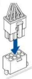


text_image
ORORNOTE: Please refer to the manual(s) for more information: Motherboard PSU
Connect cables from Chassis
7 Connect everything to the motherboard
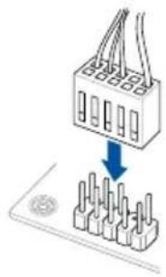
- Front panel header
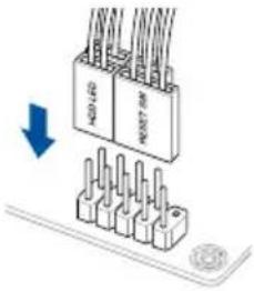
text_image
Diagram showing a connector with labeled pins and a blue downward arrow indicating direction, likely illustrating a process or assembly.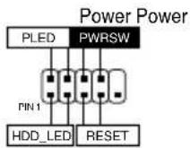
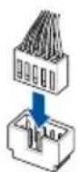
OR

natural_image
Diagram of a connector with pins and wiring, showing a downward arrow (no text or symbols present)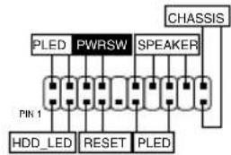
flowchart
graph TD
    A["PLED"] --> B["PWRSW"]
    B --> C["SPEAKER"]
    C --> D["CHASSIS"]
    E["Pin 1"] --> F["HDD_LED"]
    F --> G["RESET"]
    G --> H["PLED"]
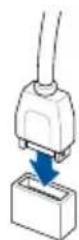
•F_AUDIO
natural_image
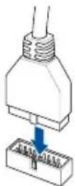
Diagram showing a crane lifting a stack of pins into a base (no text or symbols)- USB connector/header
NOTE: Please refer to the manual(s) for more information:
Motherboard Chassis
Connect cables from PSU
- SATA

natural_image
Diagram of an Ethernet cable connector with port connections (no text or labels)NOTE: Please refer to the manual(s) for more information: Motherboard
Connect cables from PSU
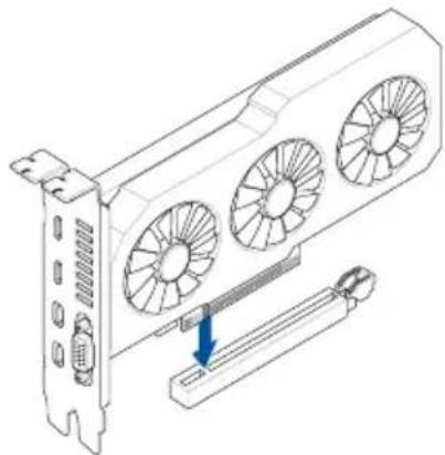
8 Install the graphics card
natural_image
Technical line drawing of a server rack with three fans and a cable inserted into a socket (no text or symbols)Please note that power connection is required for selected models.
NOTE: Please refer to the manual(s) for more information:
Motherboard Chassis Graphi cs Card

natural_image
Cartoon character resembling a mouse wearing a red outfit and waving (no text or symbols)9 Connect to the Internet via Ethernet/Wi-Fi antenna

natural_image
Line drawing of a server rack with an attached cable and a blue arrow pointing to a component (no text or symbols present)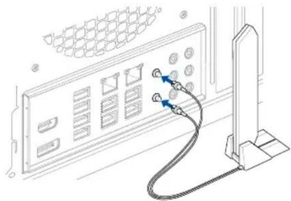
natural_image
Line drawing of a server rack with connected cables and connectors (no text or symbols)NOTE: Please refer to the manual(s) for more information: Motherboard
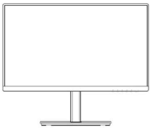
10 Connect peripherals (monitor, keyboard, mouse, etc.)
natural_image
Line drawing of a flat-screen computer monitor with a blank screen and stand (no text or symbols)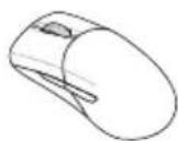

natural_image
Line drawing of a standard computer keyboard layout with no text or symbols11 Turn on the PSU and your PC
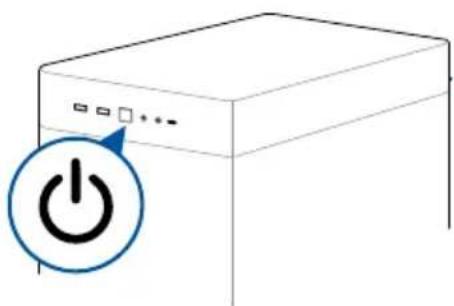
natural_image
Illustration of a server unit with a power button icon (no text or symbols)
natural_image
Diagram showing a device with an attached cable and a blue arrow pointing to it (no text or symbols present)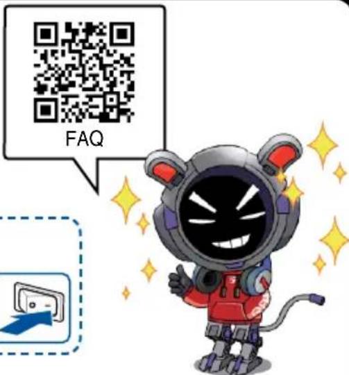
text_image
FAQNOTE: Please check the Q-LEDs or Q-LED core on selected motherboards when powering on your PC for system status. If an error occurs, check if your CPU Fan header is properly connected; you can also scan the code or refer to the manual(s) for more information: Motherboard
12
Install the operating system and drivers

text_image
QR code image containing encoded data, no visible human-readable textDriver and Utilities installation
Стъпки:
• To prevent electrical shock hazard, disconnect the power cable from the electrical outlet before relocating the system.
- When adding or removing devices to or from the system, ensure that the power cables for the devices are unplugged before the signal cables are connected. If possible, disconnect all power cables from the existing system before you add a device.
- Before connecting or removing signal cables from the motherboard, ensure that all power cables are unplugged.
- Seek professional assistance before using an adapter or extension cord. These devices could interrupt the grounding circuit.
- Ensure that your power supply is set to the correct voltage in your area. If you are not sure about the voltage of the electrical outlet you are using, contact your local power company.
• If the power supply is broken, do not try to fix it by yourself. Contact a qualified service technician or your retailer.
Operation safety
- Before installing the motherboard and adding devices on it, carefully read all the manuals that came with the package.
- Before using the product, ensure all cables are correctly connected and the power cables are not damaged. If you detect any damage, contact your dealer immediately.
- To avoid short circuits, keep paper clips, screws, and staples away from connectors, slots, sockets and circuitry.
- Avoid dust, humidity, and temperature extremes. Do not place the product in any area where it may become wet.
- Place the product on a stable surface.
- If you encounter technical problems with the product, contact a qualified service technician or your retailer.
- Your motherboard should only be used in environments with ambient temperatures between 10^ and 35^ .
Button/Coin Batteries Safety Information
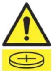
text_image
Warning symbol with exclamation mark and coin icon, indicating caution or hazard
WARNING
KEEP OUT OF REACH OF CHILDREN
Swallowing can lead to chemical burns, perforation of soft tissue, and death. Severe burns can occur within 2 hours of ingestion. Seek medical attention immediately.

General Notices
FCC Compliance Information
Responsible Party: Asus Computer International
Address: 48720 Kato Rd., Fremont, CA 94538, USA
Phone / Fax No: (510)739-3777 / (510)608-4555
This device complies with part 15 of the FCC Rules. Operation is subject to the following two conditions: (1) This device may not cause harmful interference, and (2) this device must accept any interference received, including interference that may cause undesired operation.
This equipment has been tested and found to comply with the limits for a Class B digital device, pursuant to part 15 of the FCC Rules. These limits are designed to provide reasonable protection against harmful interference in a residential installation. This equipment generates, uses and can radiate radio frequency energy and, if not installed and used in accordance with the instructions, may cause harmful interference to radio communications. However, there is no guarantee that interference will not occur in a particular installation. If this equipment does cause harmful interference to radio or television reception, which can be determined by turning the equipment off and on, the user is encouraged to try to correct the interference by one or more of the following measures:
- Reorient or relocate the receiving antenna.
- Increase the separation between the equipment and receiver.
- Connect the equipment into an outlet on a circuit different from that to which the receiver is connected.
- Consult the dealer or an experienced radio/TV technician for help.
HDMI Trademark Notice
The terms HDMI, HDMI High-Definition Multimedia Interface, HDMI Trade dress, and the HDMI Logo are trademarks or registered trademarks of HDMI Licensing Administrator, Inc.

text_image
HDMI™HIGH-DEFINITION MULTIMEDIA INTERFACE
Safety Precautions
Accessories that came with this product have been designed and verified for the use in connection with this product. Never use accessories for other products to prevent the risk of electric shock or fire.
安全上のご注意
Declaration of compliance for product environmental regulation
ASUS follows the green design concept to design and manufacture our products, and makes sure that each stage of the product life cycle of ASUS product is in line with global environmental regulations. In addition, ASUS disclose the relevant information based on regulation requirements.
Please refer to http://csr.asus.com/Compliance.htm for information disclosure based on regulation requirements ASUS is complied with:
EU REACH and Article 33
Complying with the REACH (Registration, Evaluation, Authorisation, and Restriction of Chemicals) regulatory framework, we published the chemical substances in our products at ASUS REACH website at http://csr.asus.com/english/REACH.htm.
EU RoHS
This product complies with the EU RoHS Directive. For more details, see http://csr.asus.com/english/article.aspx?id=35
India RoHS
This product complies with the “India E-Waste (Management) Rules, 2016” and prohibits use of lead, mercury, hexavalent chromium, polybrominated biphenyls (PBBs) and polybrominated diphenyl ethers (PBDEs) in concentrations exceeding 0.1% by weight in homogenous materials and 0.01% by weight in homogenous materials for cadmium, except for the exemptions listed in Schedule II of the Rule.
Vietnam RoHS
ASUS products sold in Vietnam, on or after September 23, 2011, meet the requirements of the Vietnam Circular 30/2011/TT-BCT.
ASUS recycling and takeback programs come from our commitment to the highest standards for protecting our environment. We believe in providing solutions for you to be able to responsibly recycle our products, batteries, other components as well as the packaging materials. Please go to http://csr.asus.com/english/Takeback.htm for detailed recycling information in different regions.
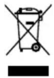
DO NOT throw the motherboard in municipal waste. This product has been designed to enable proper reuse of parts and recycling. This symbol of the crossed out wheeled bin indicates that the product (electrical and electronic equipment) should not be placed in municipal waste. Check local regulations for disposal of electronic products.
DO NOT throw the mercury-containing button cell battery in municipal waste. This symbol of the crossed out wheeled bin indicates that the battery should not be placed in municipal waste.
France sorting and recycling information


Notices for Wi-Fi model
FCC RF Caution Statement
WARNING: Any changes or modifications not expressly approved by the party responsible for compliance could void your authority to operate the equipment.
FCC Wi-Fi Caution Statement
Operation of transmitters in the 5.925-7.125 GHz band is prohibited for control of or communications with unmanned aircraft systems.
RF exposure warning
This equipment must be installed and operated in accordance with provided instructions and the antenna(s) used for this transmitter must be installed to provide a separation distance of at least 20 cm from all persons and must not be co-located or operating in conjunction with any other antenna or transmitter. End-users and installers must be provide with antenna installation instructions and transmitter operating conditions for satisfying RF exposure compliance.
Compliance Statement of Innovation, Science and Economic Development Canada (ISED)
This device complies with Innovation, Science and Economic Development Canada licence exempt RSS standard(s). Operation is subject to the following two conditions: (1) this device may not cause interference, and (2) this device must accept any interference, including interference that may cause undesired operation of the device. Operation in the band 5150–5250 MHz is only for indoor use to reduce the potential for harmful interference to co-channel mobile satellite systems.
CAN ICES-003(B)/NMB-003(B)
ISED Wi-Fi Caution Statement (RLAN devices)
Devices shall not be used for control of or communications with unmanned aircraft systems.
KC: Korea Warning Statement
B급 기기 (가정용 방송통신기자재)
NCC: Wireless Statement
Japan RF Equipment Statement
屋外での使用について
Simplified UKCA Declaration of Conformity
ASUSTek Computer Inc. hereby declares that this device is in compliance with the essential requirements and other relevant provisions of The Radio Equipment Regulations 2017 (S.I. 2017/1206). Full text of UKCA declaration of conformity is available at https://www.asus.com/support/.
The WiFi operating in the band 5150-5350MHz shall be restricted to indoor use for the country listed below:
UK
UKCA RF Output table (The Radio Equipment Regulations 2017)
Model: BE200NGW
a. Low Power Indoor (LPI) Wi-Fi devices:
The device is restricted to indoor use only when operating in the 5925 to 6425 MHz frequency range in UK.
b. Very Low Power (VLP) Wi-Fi devices (portable devices):
The device is not permitted to be used on Unmanned Aircraft Systems (UAS) when operating in the 5925 to 6425 MHz frequency range in UK.
| Function Frequency Maximum Output Power (EIRP) | |
| WiFi | 2412 - 2472 MHz 19 dBm |
| 5150 - 5350 MHz 21 dBm | |
| 5470 - 5725 MHz 21 dBm | |
| 5725 - 5850 MHz 12 dBm | |
| 5945 - 6425 MHz 21 dBm | |
| Bluetooth 2402 - 2480 MHz 17 dBm | |
* Receiver Category 1
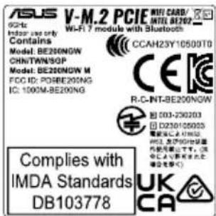
text_image
ASUS V-M.2 PCIE WIFI CARD/INTEL BE200 GC-1c Wi-Fi 7 module with Bluetooth Indoor cap only Contains Model: BE200NGW CCAH23Y10500T0 CHN/TAN/9GP CE Model: BE200NGW M FCC ID: P08BE200NG R-C-INT-BE200NGW IC: 1000M-BE200NG Complies with IMDA Standards DB103778 UK CASimplified EU Declaration of Conformity
Simplified EU Declaration of Conformity
ASUSTek Computer Inc. hereby declares that this device is in compliance with the essential requirements and other relevant provisions of Directive 2014/53/EU. Full text of EU declaration of conformity is available at https://www.asus.com/support/.
The WiFi operating in the band 5150-5350MHz shall be restricted to indoor use for countries listed in the table below:
a. Low Power Indoor (LPI) Wi-Fi devices:
The device is restricted to indoor use only when operating in the 5945 to 6425 MHz frequency range in Belgium (BE), Bulgaria (BG), Cyprus (CY), Czech Republic (CZ), Estonia (EE), France (FR), Iceland (IS), Ireland (IE), Lithuania (LT), Germany (DE), Netherlands (NL), Spain (ES).
b. Very Low Power (VLP) Wi-Fi devices (portable devices):
The device is not permitted to be used on Unmanned Aircraft Systems (UAS) when operating in the 5945 to 6425 MHz frequency range in Belgium (BE), Bulgaria (BG), Cyprus (CY), Czech Republic (CZ), Estonia (EE), France (FR), Iceland (IS), Ireland (IE), Lithuania (LT), Germany (DE), Netherlands (NL), Spain (ES).
https://www.asus.com/support/.
https://www.asus.com/support/
https://www.asus.com/support/
* Receiver Category 1

text_image
ASUS V-M.2 PCIE WIFI CARD: R 8GHz enter use only Contains Model: BE200NGW CHINTWIN5GP Model: BE200NGW M FOC D: PD98E200NG IC: 1000A-BE200NG COMplies with IMDA Standards DB103778 CCAH-23Y10500T0 CEK R-C4NT-BE200NGW □ 093-230203 □ D230105003 电源接口与WBS、 WB、及VCS/USB等 为使用器上です。 (I) 型号: 168(非标称)或 安全带(≤)Warranty
EN: ASUS Guarantee Information
- ASUS offers a voluntary manufacturer's Commercial Guarantee.
• ASUS reserves the right to interpret the provisions of the ASUS Commercial Guarantee.
- This ASUS Commercial Guarantee is provided independently and in addition to the statutory Legal Guarantee and in no way affects or limits the rights under the Legal Guarantee.
For all the guarantee information, please visit https://www.asus.com/support.
F: Garantie ASUS
https://www.asus.com/vn/support

text_image
QR code image containing encoded data, no visible human-readable textASUS contact information
ASUSTeK COMPUTER INC.
Address: 1F., No. 15, Lide Rd., Beitou Dist., Taipei City 112
ASUS COMPUTER INTERNATIONAL (America)
Address: 48720 Kato Rd., Fremont, CA 94538, USA
ASUS COMPUTER GmbH (Germany and Austria)
Address: Harkortstrasse 21-23, 40880 Ratingen, Germany
ASUSTeK (UK) LIMITED
Address: 1st Floor, Sackville House, 143-149 Fenchurch Street, London, EC3M 6BL, England, United Kingdom
Service and Support
Visit our multi-language website at https://www.asus.com/support.

text_image
QR code with embedded logo and text 'ASUS' in centerProduct Register
Log in and register your device for better product support.

text_image
QR code image containing encoded data, no visible human-readable text
natural_image
Abstract red logo design with stylized flame-like shapes (no text or symbols)REPUBLIC OF GAMERS