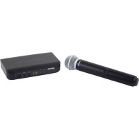
BLX24 - Microphone SHURE - Free user manual and instructions
Find the device manual for free BLX24 SHURE in PDF.



| Product Type | Wireless microphone with receiver (BLX24 system) |
| Brand | Shure |
| Model | BLX24 |
| Category | Microphone |
| Receiver dimensions (BLX4/BLX88) | Approximately 40 x 181 x 103 mm (not exactly specified) |
| Handheld transmitter dimensions (BLX2) | 224 mm x 53 mm diameter |
| Handheld transmitter weight (without batteries) | 218 g |
| Transmitter power supply | 2 AA LR6 1.5 V alkaline batteries (or compatible Shure rechargeables) |
| Battery life (transmitter) | Up to 14 hours (depending on type and manufacturer) |
| Receiver power supply | DC power adapter (included) |
| Operating range | 91 m (300 ft) line-of-sight |
| Audio frequency response | 50 to 15,000 Hz (depending on microphone) |
| Total harmonic distortion | 0.5% typical (at ±33 kHz deviation, 1 kHz) |
| Dynamic range | 100 dB (A-weighted, typical) |
| Operating temperature | -18°C to 57°C (batteries may limit) |
| Output impedance (XLR receiver) | 200 Ω |
| Output impedance (6.35 mm receiver) | 50 Ω |
| Audio output level (XLR) | -27 dBV (at ±33 kHz deviation, 1 kHz, 100 kΩ load) |
| Audio output level (6.35 mm) | -13 dBV (same conditions) |
| RF sensitivity | -105 dBm for 12 dB SINAD (typical) |
| Image frequency rejection | 50 dB (typical) |
| Main features | Automatic group/channel scanning, gain adjustment, control lock, LED indicators |
| Maintenance and cleaning | Clean with a dry cloth, do not use near water |
| Safety | Do not expose to rain or moisture, use only specified accessories, refer servicing to qualified personnel |
| Spare parts and repairability | Standard AA batteries, optional identification caps, repair by authorized service |
| Certifications | FCC Part 74, IC RSS-123/RSS-102, CE, ICES-003 Class B standard |
Frequently Asked Questions - BLX24 SHURE
User questions about BLX24 SHURE
0 question about this device. Answer the ones you know or ask your own.
Ask a new question about this device
Download the instructions for your Microphone in PDF format for free! Find your manual BLX24 - SHURE and take your electronic device back in hand. On this page are published all the documents necessary for the use of your device. BLX24 by SHURE.
USER MANUAL BLX24 SHURE

natural_image
Line drawing of a vintage microphone with control panel and speaker (no text or symbols)IMPORTANT SAFETY INSTRUCTIONS
-
READ these instructions.
-
KEEP these instructions.
-
HEED all warnings.
-
FOLLOW all instructions.
-
DO NOT use this apparatus near water.
-
CLEAN ONLY with dry cloth
-
DO NOT block any ventilation openings. Allow sufficient distances for adequate ventilation and install in accordance with the manufacturer's instructions.
-
DO NOT install near any heat sources such as open flames, radiators, heat registers, stoves, or other apparatus (including amplifiers) that produce heat. Do not place any open flame sources on the product.
-
DO NOT defeat the safety purpose of the polarized or groundingtype plug. A polarized plug has two blades with one wider than the other. A grounding type plug has two blades and a third grounding prong. The wider blade or the third prong are provided for your safety. If the provided plug does not fit into your outlet, consult an electrician for replacement of the obsolete outlet.
-
PROTECT the power cord from being walked on or pinched, particularly at plugs, convenience receptacles, and the point where they exit from the apparatus.
-
ONLY USE attachments/accessories specified by the manufacturer.
-
USE only with a cart, stand, tripod, bracket, or table specified by the manufacturer, or sold with the apparatus. When a cart is used, use caution when moving the cart/apparatus combination to avoid injury from tip-over.
-
UNPLUG this apparatus during lightning storms or when unused for long periods of time.

-
REFER all servicing to qualified service personnel. Servicing is required when the apparatus has been damaged in any way, such as power supply cord or plug is damaged, liquid has been spilled or objects have fallen into the apparatus, the apparatus has been exposed to rain or moisture, does not operate normally, or has been dropped.
-
DO NOT expose the apparatus to dripping and splashing. DO NOT put objects filled with liquids, such as vases, on the apparatus.
-
The MAINS plug or an appliance coupler shall remain readily operable.
-
The airborne noise of the Apparatus does not exceed 70dB (A).
-
Apparatus with CLASS I construction shall be connected to a MAINS socket outlet with a protective earthing connection.
-
To reduce the risk of fire or electric shock, do not expose this apparatus to rain or moisture.
-
Do not attempt to modify this product. Doing so could result in personal injury and/or product failure.
-
Operate this product within its specified operating temperature range.

This symbol indicates that dangerous voltage constituting a risk of electric shock is present within this unit.

This symbol indicates that there are important operating and maintenance instructions in the literature accompanying this unit.
WARNING: This product contains a chemical known to the State of California to cause cancer and birth defects or other reproductive harm.
CONSIGNES DE SÉCURITÉ IMPORTANTES
For proper operation, set each transmitter to a different channel on the BLX88 receiver.
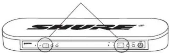
Consult your BLX Channel guide to select compatible channel sets.
Attention
Connect receiver to power source.
natural_image
Line drawing of a device with connected cables and ports (no text or symbols)b)
Connect receiver to mixer or amplifier. Hold power button to turn on.
natural_image
Illustration of a person speaking at a podium with an abacus and a device, no text or symbols present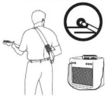
natural_image
Illustration of a person holding a device, a circular dial indicator, and an electric vehicle (no text or symbols)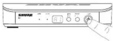

Press group button on receiver to perform a group scan.
Install batteries and turn on transmitter.
Instale as pilhas e ligue o transmissor.
natural_image
Technical line drawing of a mechanical device with no visible text or symbolsb)
On the transmitter, set the group and channel to match the receiver. The audio LED on the receiver should illuminate.

If setting up additional systems, leave the first transmitter and receiver on. For each additional receiver, manually set the group to match the first receiver.
Note: The receiver will automatically perform a channel scan to find an available frequency after the group has been selected. Set the transmitter frequency to match the receiver.
If sound is too faint or distorted, adjust the gain accordingly.
BLX
Features
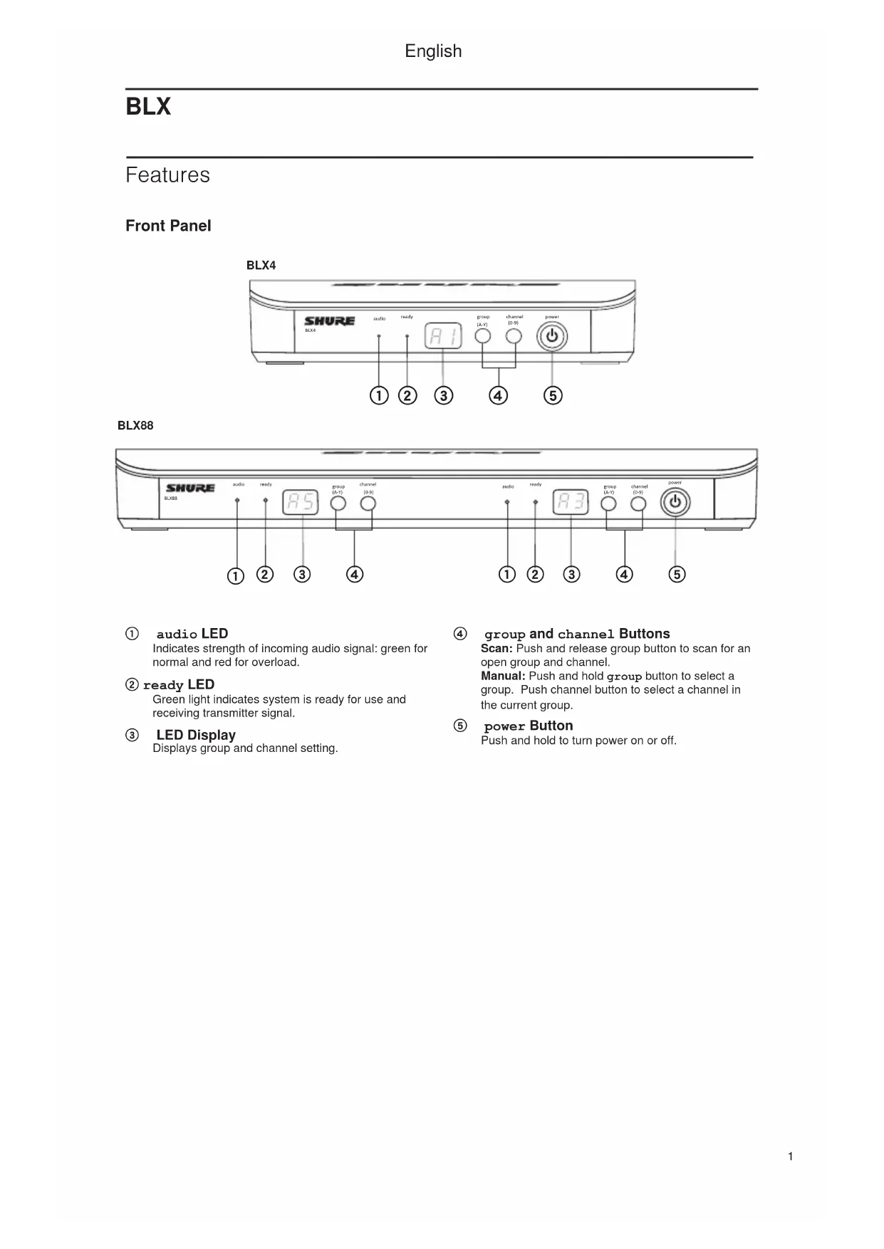
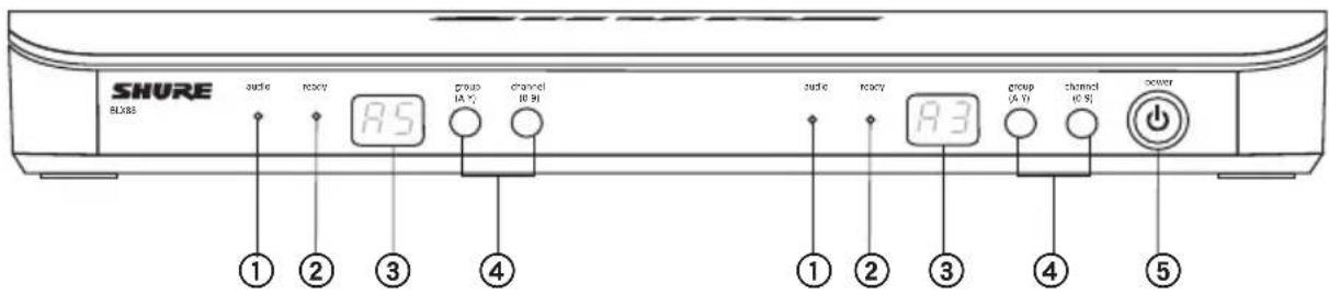
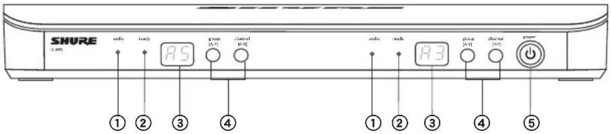
Front Panel
BLX4
BLX88
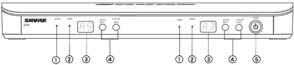
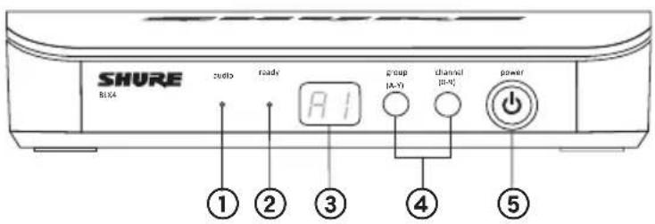
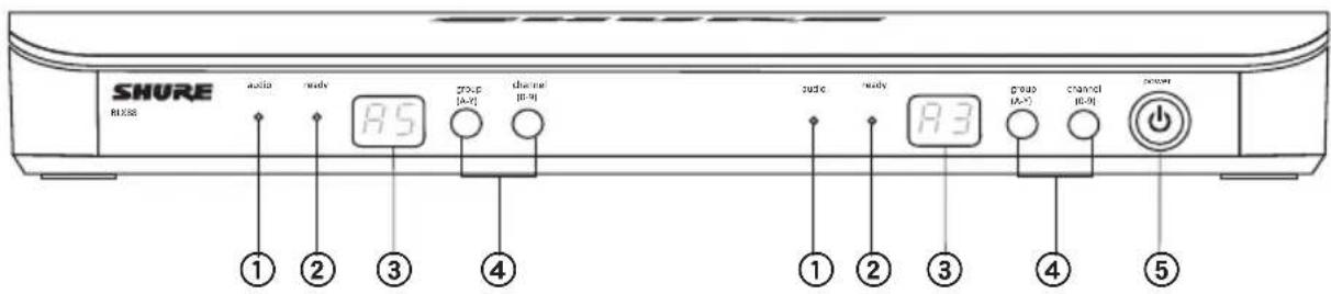
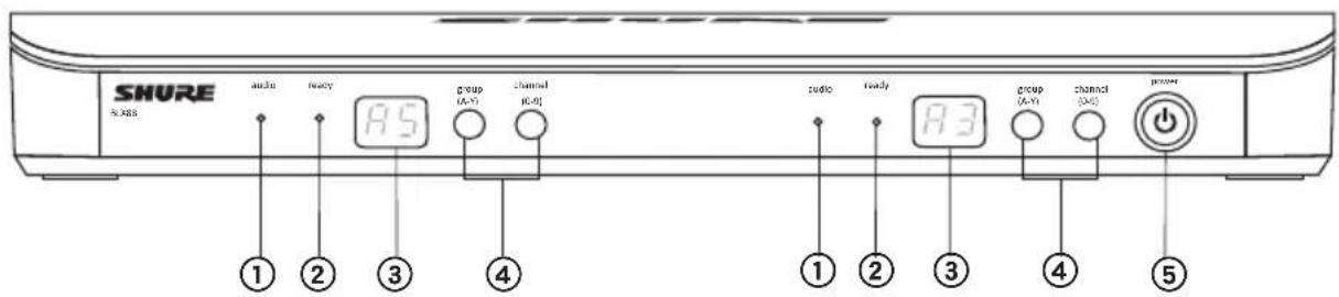
① audio LED
Indicates strength of incoming audio signal: green for normal and red for overload.
② ready LED
Green light indicates system is ready for use and receiving transmitter signal.
③ LED Display
Displays group and channel setting.
④ group and channel Buttons
Scan: Push and release group button to scan for an open group and channel.
Manual: Push and hold group button to select a group. Push channel button to select a channel in the current group.
⑤ power Button
Push and hold to turn power on or off.
English
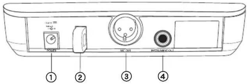
Back Panel
BLX4
BLX88
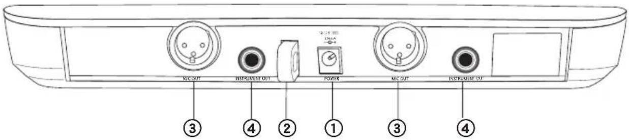
① DC Power Jack
② Adapter Cord Tie-Off
③ XLR microphone output jack (MICout)
④ 6.35 mm (1/4") instrument level output jack (instrumentout)
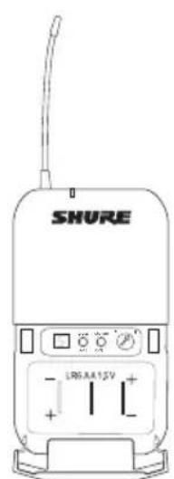
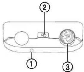
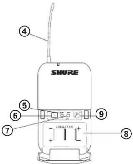
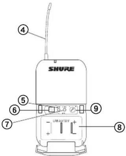
BLX1
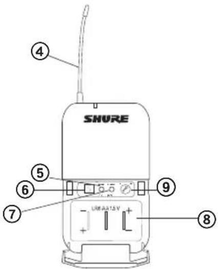
① LED Indicator
Displays power and battery status (see
Transmitter LED Indicators).
② power Switch
Toggles power on or off.
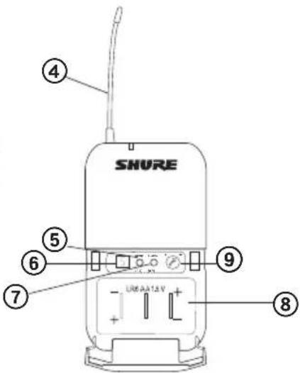
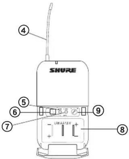
③ 4-Pin Microphone Input Jack (TA4
connector)
④ Antenna
⑤ group Button
Changes group setting.
⑥ LED Display
Displays group and channel setting.
⑦ channel Button
Changes channel setting.
⑧ Battery Compartment
⑨ Audio Gain Adjustment
Rotate to increase or decrease transmitter gain.
BLX1
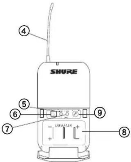
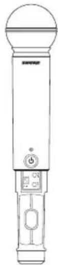
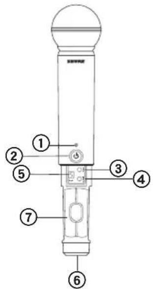
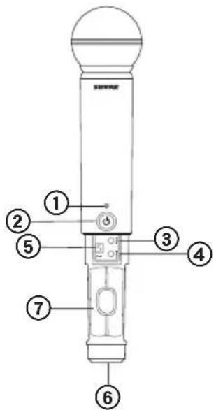
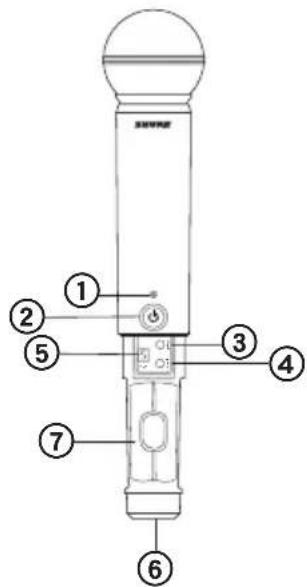
BLX2
① LED Indicator
Displays power and battery status (see Transmitter LED Indicators).
② power Button
Push to turn power on or off.
③ group Button
Changes group setting.
④ channel Button
Changes channel and gain setting.
⑤ LED Display
Displays group and channel setting.
⑥ Identification Cap
⑦ Battery Compartment
BLX2
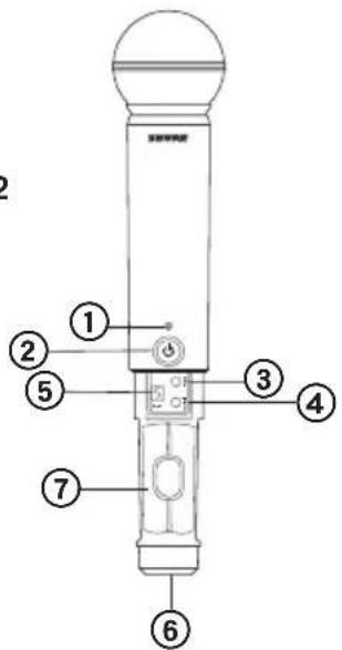
Transmitter LED Indicators
| LED Indicator Status | |
| Green Ready | |
| Rapidly Flashing Red Controls locked | |
| Solid Red Battery power low (less than 1 hour remaining*) | |
| Flashing Red and shuts off Batteries dead (change batteries to power on transmitter) | |
*For alkaline batteries only. For rechargeable batteries, solid red means the batteries are dead.
Single System Set Up
Before you begin, turn off all transmitters and turn on any equipment (other microphones or personal monitoring systems) that could cause interference during the performance.
flowchart
graph LR
    A["Hand pointing at BOS (6.4)"] --> B["A1"]
    B --> C["B3"]
    C --> D["E2"]
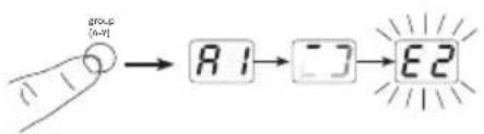
- Press and release the group button on the receiver.
The receiver scans for the clearest group and channel.
Note: If you want to stop the scan, push the group button again.
- Turn on transmitter and change the group and channel to match the receiver (See Setting Transmitter Group and Channel).
Once the system is set up, perform an audio check and adjust the gain if necessary.
Setting Transmitter Group and Channel
Transmitter group and channel must be manually set to match the receiver.
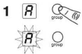
Group (letter)
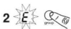
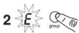
- Press and release the group button on the transmitter to activate the display. Press the group button again and the display flashes.
- While the display is flashing, press the group button again to advance to the desired group setting.
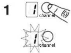
Channel (number)
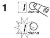
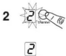
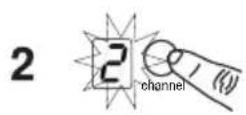
If channel needs to be changed, follow the same procedure using the channel button instead of the group button.
Note:
- When the group and channel correctly match the receiver, the ready LED on receiver illuminates.
• After manual setup, the transmitter alternately displays the group and channel setting for about two seconds.
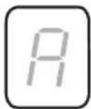
groupchannel
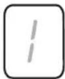
1
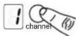
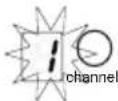
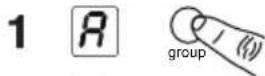


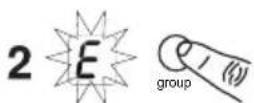
2
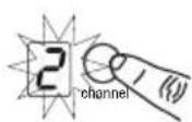
Multiple System Setup
Up to 12 systems can operate simultaneously (band and RF environment dependent).
Important: Set up each system one-at-a-time. Once a receiver and transmitter are tuned to the same group and channel, leave the transmitter powered on. Otherwise, scans from the other receivers will not detect that channel as occupied. For the BLX88, be sure to setup both transmitters before progressing to the next receiver.
Turn on any other equipment that could cause interference during the performance so it will be detected during the group and channel scans in the following steps.
Before you begin system set up, turn all receivers ON and all transmitters OFF.
For the first receiver:
- Perform a group scan.
This finds the group with the most clear channels.
Note: For the BLX88, the group scan sets up both receivers at the same time.
-
Turn on the first transmitter and change the group and channel to match receiver.
-
Leave the transmitter on and continue with the additional systems.
Note: If the selected group does not contain enough open channels, manually select group "d" when setting up larger systems.
For each additional receiver:
- Use manual setup to change the receiver to match the group setting of the first receiver. Recall that each time the group setting is changed, a channel scan is automatically done.
- Turn on the transmitter and change the group and channel to match the receiver.
- Leave the transmitter on and continue to the next system.
- Once all receivers are set up, perform an audio check on all microphones.
Manually Setting Receiver Group and Channel
The receiver group may need to be changed as part of a multiple system setup.
Group (letter)
- Hold the group button on the receiver until the display begins to flash.
- While the display is flashing, press the group button again to advance to the next group.
Note: Only the group setting will be displayed during the manual setup. - Once the desired group is reached, release the group button. The receiver automatically performs a channel scan.
Channel (number)
Always use a channel selected by the channel scan. However, if necessary, the channel can be set manually. Follow the same steps above using the channel button instead of the group button.
Locking and Unlocking Controls
Lock system controls to prevent accidental setting changes or power off.
Transmitter (lock/unlock)
Turn the transmitter on. Hold the group button, then press the channel button for approximately 2 seconds. The LED indicator rapidly flashes red when locked.
Receiver (lock/unlock)
Turn the receiver on. Simultaneously hold the group and channel button. The display flashes rapidly.
- When locked, the display flashes rapidly if any key is pressed.
- The BLX88 locks on both sides when locked from either side.
Tips to Improve Wireless System Performance
If you encounter interference or dropouts, try the following suggestions:
- Choose a different receiver channel
- Reposition the receiver so there is nothing obstructing a line of sight to the transmitter (including the audience)
- Avoid placing transmitter and receiver where metal or other dense materials may be present
- Move the receiver to the top of the equipment rack
- Remove nearby sources of wireless interference, such as cell phones, two-way radios, computers, media players, Wi-Fi devices, and digital signal processors
- Charge or replace the transmitter battery
- Keep transmitters more than two meters (6 feet) apart
- Keep the transmitter and receiver more than 5 meters (16 feet) apart
- During sound check, mark trouble spots and ask presenters or performers to avoid those areas
Getting Good Sound
Correct Microphone Placement
- Hold the microphone within 12 inches from the sound source. For a warmer sound with increased bass presence, move the microphone closer.
- Do not cover grille with hand.
Wearing the Headworn Microphone
- Position the headworn microphone 13 mm (1/2 in.) from the corner of your mouth.
- Position lavalier and headworn microphones so that clothing, jewelry, or other items do not bump or rub against the microphone.
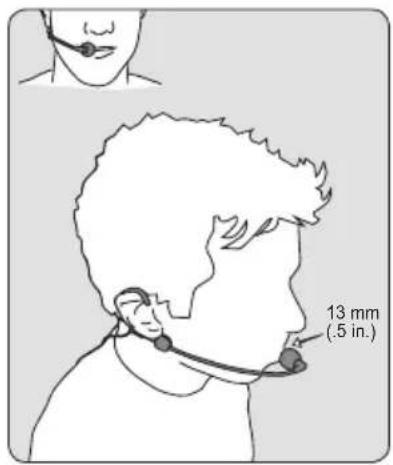
Adjusting Gain
Monitor the audio LED indicator on the receiver front panel when setting the transmitter gain.
- Green: normal levels
• Red: excessive sound levels (overload).
The red LED should only illuminate infrequently when you speak loudly or play your instrument loudly.
BLX1
Rotate the audio gain adjustment to increase (+) or decrease (−) the gain until desired level is reached.
For instruments, turn gain to minimum setting. For lavaliers, increase the gain as desired.
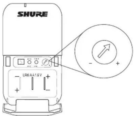
BLX2
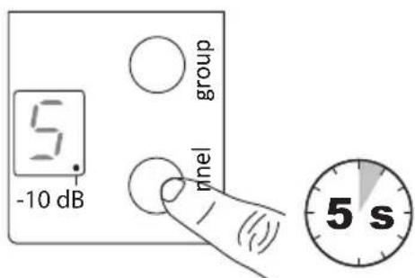
The BLX2 features two gain level settings, default and attenuated (-10 dB). The default setting is used for most situations. If the receiver audio LED flickers red often, set the microphone to attenuated. Use the channel button to change the gain setting.
- Hold down the channel button for 5 seconds.
A dot appears on the lower right-hand corner of the LED display, which indicates -10 dB gain setting has been activated. - To change the gain back to default, hold the channel button again for 5 seconds, or until the dot disappears.
Batteries
Expected life for AA batteries is up to 14 hours (total battery life varies depending upon battery type and manufacturer).
When the LED indicator turns red, it signifies "low battery" with approximately 60 minutes of remaining battery life.
For alkaline batteries only. For rechargeable batteries, solid red means the batteries are dead.
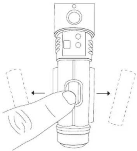
To remove batteries from the handheld transmitter, push them out through the opening in the microphone battery compartment.

WARNING: Danger of explosion if battery incorrectly replaced. Operate only with Shure compatible batteries.

WARNING: Battery packs shall not be exposed to excessive heat such as sunshine, fire, or the like.
natural_image
Diagram of a hand pressing a button on a mechanical component, with dashed arrows indicating direction (no text or symbols)Wearing the Bodypack Transmitter
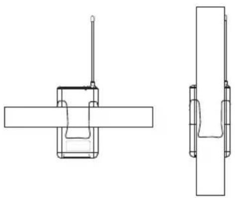
Clip the transmitter to a belt or slide a guitar strap through the transmitter clip as shown.
For best results, the belt should be pressed against the base of the clip.
natural_image
Technical line drawing of a mechanical assembly with cross-sectional and top views (no text or symbols)Power Off
Hold down the power button to power off the BLX2 or BLX4/88. To power off the BLX1, slide the power toggle switch to OFF.
Removing and Installing Identification Caps
The BLX2 is equipped with a black identification cap from the factory (dual vocal systems ship with additional gray cap).
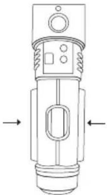
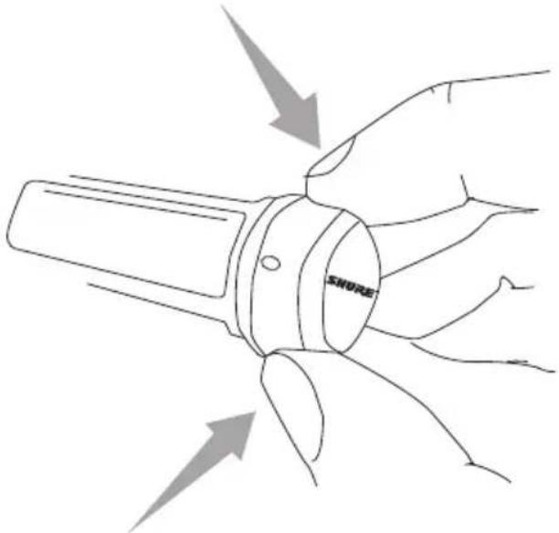
To remove: Remove battery cover. Squeeze sides and pull off cap.
To install: Align the cap and click into place. Replace battery cover.
An Identification Cap Kit containing assorted colored caps is available as an optional accessory.
natural_image
Line drawing of a hand holding a device with arrows indicating motion or force (no text or symbols)Troubleshooting
| Issue Indicator Status Solution | ||
| No sound or faint sound | Receiver ready LED on | ·Verify all sound system connections or adjust gain as needed (see Adjusting Gain)·Verify that the receiver is connected to mixer/amplifier |
| Receiver ready LED off · Turn | on transmitter·Make sure the batteries are installed correctly·Perform transmitter setup (see Single System Setup)·Insert fresh batteries | |
| Receiver LED screen off · Make | sure DC adapter is securely plugged into electrical outlet.·Make sure receiver is powered on. | |
| Transmitter indicator LED flashing red | Replace transmitter batteries (see Changing Batteries). | |
| Audio artifacts or dropouts Ready LED flickering or off · Change | receiver and transmitter to a different group and/or channel.·Identify nearby sources of RF interference, and shutdown or remove source.·Replace transmitter batteries.·Ensure that receiver and transmitter are positioned within system parameters·System must be set up within recommended range and receiver kept away from metallic surfaces.·Transmitter must be used in line of sight from receiver for optimal sound | |
| Distortion Audio LED on receiver indicates overload (red) | Reduce transmitter gain (see Adjusting Gain). | |
| Sound level variations when switching to different sources | N/A Adjust transmitter gain as necessary (see Adjusting Gain). | |
| Receiver/transmitter won't turn off | LED/display flashing rapidly See Locking and Unlocking Controls. | |
BLX
Working Range
91 m (300 ft) Line of Sight
Note: Actual range depends on RF signal absorption, reflection and interference.
Audio Frequency Response
50 to 15,000 Hz
Note: Dependent on microphone type
Total Harmonic Distortion
Ref. ±33 kHz deviation with 1 kHz tone
0.5%, typical
Dynamic Range
100 dB, A-weighted, typical
Operating Temperature
-18°C (0°F) to 57°C (135°F)
Note: Battery characteristics may limit this range.
Polarity
Positive pressure on microphone diaphragm (or positive voltage applied to tip of WA302 phone plug) produces positive voltage on pin 2 (with respect to pin 3 of low-impedance output) and the tip of the 1/4-inch output.
BLX1
Audio Input Level
| gain max -16 dBV maximum | |
| min (0 dB) +10 dBV maximum | |
Gain Adjustment Range
26 dB
Input Impedance
1 MΩ
RF Transmitter Output
10 mW, typical
varies by region
Dimensions
110 mm x 64 mm x 21 mm (H x W x D)
Weight
75 g (2.6 oz.), without batteries
Housing
Molded ABS
Power Requirements
2 LR6 AA batteries, 1.5 V, alkaline
Battery Life
up to 14 hours (alkaline)
BLX2
Audio Input Level
| gain 0dB -20 dBV | maximum | |
| -10dB -10 dBV maximum | ||
Gain Adjustment Range
10 dB
RF Transmitter Output
10 mW, typical
varies by region
Dimensions
224 mm X 53 mm dia. (8 7/8 X 2 1/8 in.)
Weight
218 g (7.7 oz.) (without batteries)
Housing
Molded ABS
Power Requirements
2 LR6 AA batteries, 1.5 V, alkaline
Battery Life
up to 14 hours (alkaline)
BLX4 & BLX88
Output Impedance
| XLR connector 200 Ω | |
| 6.35 mm (1/4") connector 50 Ω |
Audio Output Level
Ref. ±33 kHz deviation with 1 kHz tone
| XLR connector -27 dBV (into 1) | 100 kΩ load |
| 6.35 mm (1/4") connector -13 | dBV (into 100 kΩ load) |
RF Sensitivity
-105 dBm for 12 dB SINAD, typical
Image Rejection
50 dB, typical
Dimensions
| BLX4 40 mm X 188 mm X 103 mm (H x W x D) |
| BLX88 40 mm X 388 mm X 116 mm (H x W x D) |
Weight
| BLX4 241 | g (8.5 oz.) |
| BLX88 429 | g (15.1 oz.) |
Housing
Molded ABS
Power Requirements
12–15 V DC @ 160 mA (BLX88, 320 mA), supplied by external power supply (tip positive)
Important Product Information
Certifications
This product meets the Essential Requirements of all relevant European directives and is eligible for CE marking.
The CE Declaration of Conformity can be obtained from Shure Incorporated or any of its European representatives.
For contact information please visit www.shure.com
The CE Declaration of Conformity can be obtained from: www.shure.com/europe/compliance
Authorized European representative:
Shure Europe GmbH
Headquarters Europe, Middle East & Africa
Department: EMEA Approval
Jakob-Dieffenbacher-Str. 12
75031 Eppingen, Germany
Phone: 49-7262-92 49 0
Fax: 49-7262-92 49 11 4
Email: EMEAsupport@shure.de
BLX1, BLX2
Certified under FCC Part 74.
Certified by IC in Canada under RSS-123 and RSS-102.
Approved under the Declaration of Conformity (DoC) provision of FCC Part 15.
| Band Range | Output Power | |
| H8E 518 to | 542 MHz 10 mW | |
| K3E 606 to | 630 MHz 10 mW | |
| K14 614 to | 638 MHz 10 mW | |
| M17 662 to | 686 MHz 10 mW | |
| Q25 742 to | 766 MHz 10 mW | |
| R12 796 to | 806 MHz 10 mW | |
| S8 823 to 8 | 32 MHz 10 mW | |
| T11 863 to | 865 MHz 10 mW |
NOTE: This Radio equipment is intended for use in musical professional entertainment and similar applications. This Radio apparatus may be capable of operating on some frequencies not authorized in your region. Please contact your national authority to obtain information on authorized frequencies and RF power levels for wireless microphone products.
LICENSING INFORMATION
Licensing: A ministerial license to operate this equipment may be required in certain areas. Consult your national authority for possible requirements. Changes or modifications not expressly approved by Shure Incorporated could void your authority to operate the equipment. Licensing of Shure wireless microphone equipment is the user's responsibility, and licensability depends on the user's classification and application, and on the selected frequency.
Shure strongly urges the user to contact the appropriate telecommunications authority concerning proper licensing, and before choosing and ordering frequencies.
Information to the user
This equipment has been tested and found to comply with the limits for a Class B digital device, pursuant to Part 15 of the FCC Rules. These limits are designed to provide reasonable protection against harmful interference in a residential installation. This equipment generates uses and can radiate radio frequency energy and, if not installed and used in accordance with the instructions, may cause harmful interference to radio communications. However, there is no guarantee that interference will not occur in a particular installation. If this equipment does cause harmful interference to radio or television reception, which can be determined by turning the equipment off and on, the user is encouraged to try to correct the interference by one or more of the following measures:
- Reorient or relocate the receiving antenna.
- Increase the separation between the equipment and the receiver.
- Connect the equipment to an outlet on a circuit different from that to which the receiver is connected.
- Consult the dealer or an experienced radio/TV technician for help.
This device complies with Industry Canada licence-exempt RSS standard(s). Operation of this device is subject to the following two conditions: (1) this device may not cause interference, and (2) this device must accept any interference, including interference that may cause undesired operation of the device.
Note: EMC conformance testing is based on the use of supplied and recommended cable types. The use of other cable types may degrade EMC performance.
Changes or modifications not expressly approved by the manufacturer could void the user's authority to operate the equipment.
Please follow your regional recycling scheme for batteries, packaging, and electronic waste.
BLX
Caractéristiques
Panneau avant
BLX4
![SHURE BOX radio ready R1 group [A-Y] channel [B-Y] power ① ② ③ ④ ⑤](/content/2026/03/492005/images/5e2a17bce38488884ecfaf6cc8de735b5ad980f27ceaacb7259b37faffc2c598.jpg)
BLX88
① LED audio
BLX2
BLX2
Français
Réglage du gain
Piles
natural_image
Diagram of a hand pressing a button on a mechanical component, with no visible text or symbolsnatural_image
Technical line drawing of a mechanical assembly with cross-sectional and top views (no text or symbols)natural_image
Line drawing of a hand holding a SMORE-branded fan with directional arrows indicating motion (no text or symbols beyond brand name)Dépannage
110 mm x 64 mm x 21 mm (H x L x P)
Poids
75 g (2,6 oz), sans piles
Boîtier
ABS moulé
Alimentation
2 LR6 Piles AA, 1.5 V, Alcaline
Autonomie des piles
| BLX4 40 | mm X 188 mm X 103 mm (H x L x P) |
| BLX88 40 | mm X 388 mm X 116 mm (H x L x P) |
Poids
| BLX4 241 | g (8,5 oz.) |
| BLX88 429 | g (15,1 oz.) |
Boîtier
ABS moulé
Alimentation
12–15 V c.c. @ 160 mA (BLX88, 320 mA), provenant d'un bloc d'alimentation externe (pointe positive)
Service : Homologation EMA
Jakob-Dieffenbacher-Str. 12
BLX88
① audio-LED
BLX2
Deutsch
Sender-LED-Anzeigen
flowchart
graph LR
    A["a"] --> B["R1"]
    B --> C["..."]
    C --> D["E2"]
Batterien/Akkus
natural_image
Diagram of a hand pressing a button on a mechanical component, with no visible text or symbolsnatural_image
Technical line drawing of a mechanical assembly with two views (top and side), no text or symbols present.natural_image
Line drawing of a hand holding a device with arrows indicating motion or force (no text or symbols)Störungssuche
BLX88
① LED audio
BLX2
Español
flowchart
graph LR
    A["a"] --> B["R1"]
    B --> C["..."]
    C --> D["E2"]
Baterías
natural_image
Technical line drawing of a mechanical assembly with cross-sectional and top views (no text or symbols)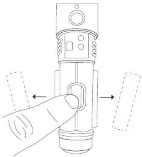
natural_image
Diagram of a hand pressing a button on a mechanical component with two dashed arrows indicating direction (no text or symbols)Apagado
natural_image
Line drawing of a hand holding a device with arrows indicating motion or force (no text or symbols)① LED audio
BLX2
BLX2
Italiano
flowchart
graph LR
    A["a"] --> B["R1"]
    B --> C["..."]
    C --> D["E2"]
Pile
natural_image
Diagram of a hand pressing a button on a mechanical device with directional arrows indicating movement (no text or symbols)natural_image
Technical line drawing of a mechanical assembly with cross-sectional and top views (no text or symbols)Spegnimento
natural_image
Line drawing of a hand holding a device with arrows indicating motion or force (no text or symbols)110 mm x 64 mm x 21 mm (A x L x P)
Peso
| BLX4 40 mm X 188 mm X 103 mm (A x L x P) |
| BLX88 40 mm X 388 mm X 116 mm (A x L x P) |
Peso
| BLX4 241 | g (8,5 oz.) |
| BLX88 429 | g (15,1 oz.) |
Alloggiamento
ABS stampato
Alimentazione
12–15 V c.c. @ 160 mA (BLX88, 320 mA), applicata da un alimentatore esterno (punta positiva)
Department: EMEA Approval
Jakob-Dieffenbacher-Str. 12
75031 Eppingen, Germania
Telefono: 49-7262-92 49 0
Fax: 49-7262-92 49 11 4
E-mail: EMEAsupport@shure.de
BLX1, BLX2
BLX88
① Светодиод audio
BLX2
Русский язык
flowchart
graph LR
    A["a"] --> B["R1"]
    B --> C["..."]
    C --> D["E2"]
Настройка усиления
Батарейки
natural_image
Technical line drawing of a mechanical assembly with two views (top and side), no text or symbols present.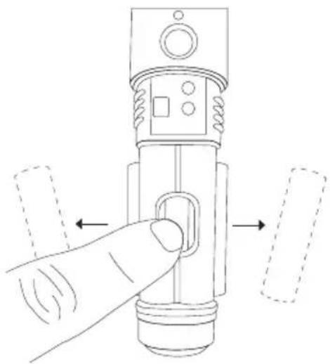
natural_image
Diagram of a hand pressing a button on a mechanical component, with dashed arrows indicating direction (no text or symbols)Выключение питания
natural_image
Line drawing of a hand holding a device with arrows indicating motion or force (no text or symbols)Headquarters Europe, Middle East & Africa
Department: EMEA Approval
Jakob-Dieffenbacher-Str. 12
75031 Eppingen, Germany
- IMPORTANT SAFETY INSTRUCTIONS
- CONSIGNES DE SÉCURITÉ IMPORTANTES
- Attention
- b)
- BLX
- Features
- Front Panel
- English
- Back Panel
- BLX1
- BLX2
- Single System Set Up
- Setting Transmitter Group and Channel
- Group (letter)
- Channel (number)
- Note:
- Multiple System Setup
- For the first receiver:
- For each additional receiver:
- Manually Setting Receiver Group and Channel
- Locking and Unlocking Controls
- Transmitter (lock/unlock)
- Receiver (lock/unlock)
- Tips to Improve Wireless System Performance
- Getting Good Sound
- Correct Microphone Placement
- Wearing the Headworn Microphone
- Adjusting Gain
- Batteries
- Wearing the Bodypack Transmitter
- Power Off
- Removing and Installing Identification Caps
- Working Range
- Audio Frequency Response
- Total Harmonic Distortion
- Dynamic Range
- Operating Temperature
- Polarity
- Gain Adjustment Range
- Input Impedance
- RF Transmitter Output
- Dimensions
- Weight
- Housing
- Power Requirements
- Battery Life
- BLX4 & BLX88
- Audio Output Level
- RF Sensitivity
- Image Rejection
- Important Product Information
- Certifications
- BLX1, BLX2
- LICENSING INFORMATION
- Information to the user
- Changes or modifications not expressly approved by the manufacturer could void the user's authority to operate the equipment.
- Caractéristiques
- Panneau avant
- ① LED audio
- Français
- Réglage du gain
- Piles
- Poids
- Boîtier
- Alimentation
- Autonomie des piles
- Deutsch
- Batterien/Akkus
- Español
- Baterías
- Apagado
- Italiano
- Pile
- Spegnimento
- Peso
- Alloggiamento
- Alimentazione
- Русский язык
- Настройка усиления
- Батарейки
- Выключение питания
Brand : SHURE
Model : BLX24
Category : Microphone