DW7463 - Industrial workbench DEWALT - Free user manual and instructions
Find the device manual for free DW7463 DEWALT in PDF.

| Product type | Industrial outfeed table for table saw |
| Brand | DeWalt |
| Model | DW7463 |
| Intended use | Table extension for DW746 table saw |
| Tabletop material | Composite panel |
| Approximate table dimensions | 762 x 610 mm (30 x 24 in) |
| Approximate weight | 18 kg (40 lb) |
| Load capacity | Designed to support heavy workpieces (no specific value provided) |
| Package contents | Outfeed table, hardware bag (bolts, nuts, washers) |
| Tools required for assembly | 16 mm (5/8 in) wrenches, hammer, tape measure |
| Compatibility | Designed exclusively for DeWalt DW746 table saw |
| Features | Adjustable feet, foldable for storage, miter gauge slots |
| Maintenance and cleaning | Clean with a damp sponge or mild solvent; avoid excessive moisture on edges |
| Storage | Disassemble by removing bolts, fold legs, store in a dry place |
| Safety | Use eye protection, do not wear loose clothing, keep hands away from blade |
| Repairability | Standard hardware parts; contact DeWalt for specific parts |
Frequently Asked Questions - DW7463 DEWALT
User questions about DW7463 DEWALT
0 question about this device. Answer the ones you know or ask your own.
Ask a new question about this device
Download the instructions for your Industrial workbench in PDF format for free! Find your manual DW7463 - DEWALT and take your electronic device back in hand. On this page are published all the documents necessary for the use of your device. DW7463 by DEWALT.
USER MANUAL DW7463 DEWALT
DEWALT Industrial Tool Co., 701 East Joppa Road, Baltimore, MD 21286
Printed in U.S.A. (JAN99-CD-1) Form No. 393165
Before returning this product call 1-800-4-DEWALT
IF YOU SHOULD EXPERIENCE A PROBLEM WITH YOUR DEWALT PURCHASE, CALL 1-800-4 DEWALT.
IN MOST CASES, A DEWALT REPRESENTATIVE CAN RESOLVE YOUR PROBLEM OVER THE PHONE.
IF YOU HAVE A SUGGESTION OR COMMENT, GIVE US A CALL. YOUR FEEDBACK IS VITAL TO THE SUCCESS OF DEWALT'S QUALITY IMPROVEMENT PROGRAM.
See our catalog on the World Wide Web. www.dewalt.com
INSTRUCTION MANUAL GUIDE D'UTILISATIONMANUAL DE INSTRUCCIONES
INSTRUCTIVO DE OPERACION, CENTROS DE SERVICIO Y POLIZA DE GARANTIA. ADVERTENCIA: LEASE THIS INSTRUCTIVO ANTES DE USAR EL PRODUCTO. SI TIENE DUDAS, POR FAVOR LLAME.
DeWALT®
DW7463
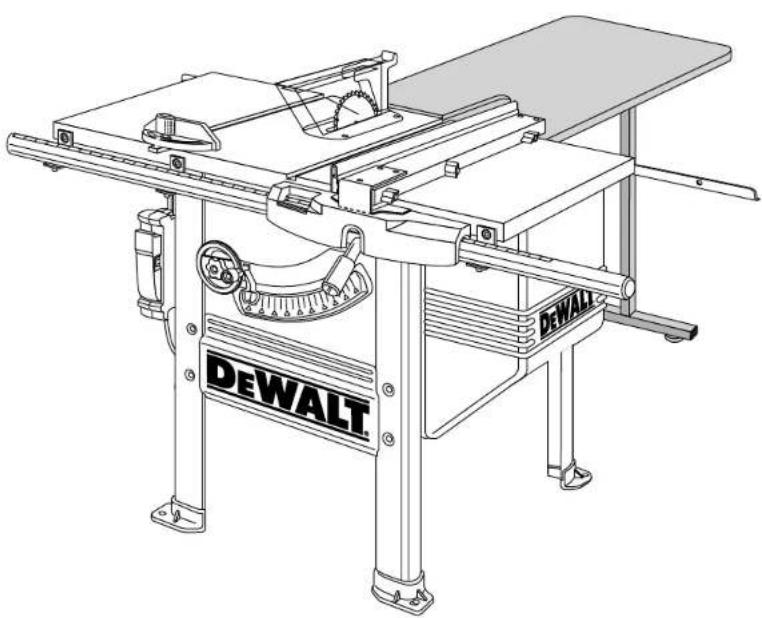
Heavy Duty Outfeed Table
For Use Only With DEWALT DW746 Table Saw
DEWALT high performance industrial tools are made for America's toughest industrial and construction applications. The design of every tool in the line - from drills to sanders to table saws - is the result of rigorous use on job sites and throughout industry. Each tool is produced with painstaking precision using advanced manufacturing systems and intense quality control. Every tool is checked before it leaves the factory to make sure that it meets your standards for durability, reliability and power.
DeWALT Built Job site Tough...WE GUARANTEE IT.
Items Included
(1) DW7463 Outfeed table sub-assembly
(1) Hardware bag
Tools needed
(2) 16mm or 5/8" open end wrenches
Ruler
- Soft hammer, or regular hammer and block of wood To speed assembly, the following would be helpful:
16mm or 5/8" socket wrench
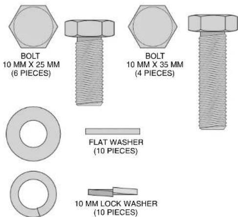
Necessary Hardware
The included hardware bag contains all the necessary nuts, bolts, and washers to assemble the components included with the DW7463 Outfeed Table and to attach it to the DW746 Woodworker's Table Saw (When attaching as an add-on use new hardware in place of removed hardware).
To make assembly of your saw/accessory easier, match the nuts, bolts, and washers with the hardware chart. Before each step, check your hardware against the chart and identify the pieces you need.
Table saw Preparation: If you purchased the Outfeed Table as an add-on accessory, start with this section. If you purchased your Outfeed Table with your DW746 Woodworker's Table Saw, skip to the assembly section.
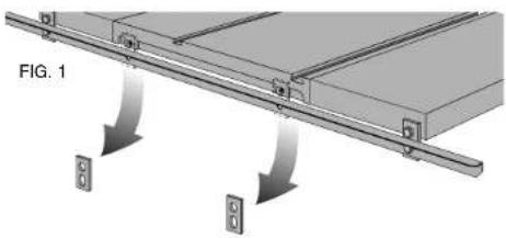
- If you have no other accessories (52" Rail System or Slide Table) on your saw, remove the rear rail and associated hardware...
- ...OR with another accessory in place remove the rear support brackets (Fig. 1) from between the saw table and the rear rail. Do not remove the rear rail.
- Continue with Assembly, starting at Step 14.
Hardware Included with the DW7463 Heavy Duty Outfeed Table
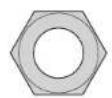
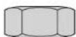
M 10 NUT 16 mm HEX (10 pieces)

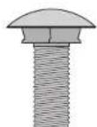
Carriage Bolt 10mm× 20mm (2 pieces)
PLEASE READ ENTIRE ASSEMBLY SECTION BEFORE PROCEEDING.
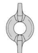
10 mm WING NUT (2 pieces)
Assembly
If you have other accessories (Slide Table and/or 52" Rail System) completely assemble them first. Then return to this manual to complete Outfeed Table Assembly, starting at step 14.
STEP 1. Remove parts box, motor cover, fence beam, and side tables from saw packaging.
STEP 2. Turn the saw right side up. You will need help. The combined weight of the table top and motor is approximately 200 lbs.
STEP 3. Cut and remove plastic strap holding the motor.
STEP 4. Using front hand crank, lower the motor some and remove the foam packing material between the motor and the mechanism.
STEP 5. Install bevel crank (Fig. 2). To do this, first install the crank handle (A) over the shaft (B), rotate slightly to fully engage the shaft pin. Screw the lock knob (C) into place until it is fully seated, then back it off 1/4 to 1/2 turn.
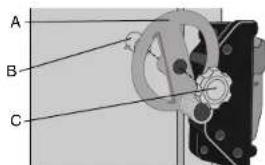
FIG.2
STEP 6. Using height crank, raise mechanism up as high as it will go.
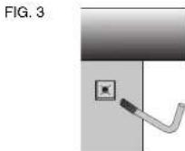
STEP 7. Install wrench hook (Fig. 3). On the front right leg, near the top is a plastic threaded insert. Thread the "L" shaped wrench hook in until no threads are visible.
STEP 8. Unpack rail carton (contains front & rear rail) and Outfeed Table carton.
STEP 9. Assemble front rail and brackets (Fig. 4).
You will need: 4 - 8mm carriage bolts (3 if adding a Slide Table)
4-8mm lock washers
4-8mm nuts
Assemble carriage bolts, washers and nuts to front rail brackets (just a few threads). Put the head of the carriage bolts into the keyhole slots in the front rail and slide to engage the square part of the bolt. Run nut until it is finger tight Repeat for other three brackets (If you are also adding a Slide Table accessory, the left most front rail bracket is not needed). When attaching brackets to the rail, the rail must be positioned so that the rip scale is right side-up. Also all 4 brackets should face the same direction
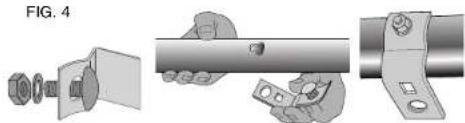
FIG.4
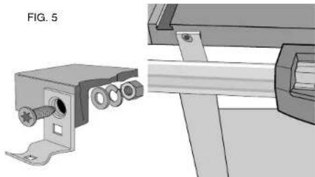
STEP 10. Attach front rail with brackets to the table top (Fig. 5)
You will need: 2 - 10 x 30mm flat head screws
2 - 10mm flat washers
2 - 10mm lock washers
2-10mm nuts
Secure each screw through the upper hole in the center brackets keeping the flat washer, lock washer and nut to the inside of the table. Tighten snug but not very tight. Tighten center rail bracket 8mm nuts, leaving the outer ones finger tight.
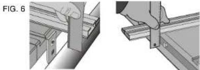
STEP 11. Parallel the front rail to the saw table (Fig. 6). Using your fence face or a straightedge to extend the table surface over the rail, make sure the distance from the saw table top to the rail top is the same at both the left and right side of the table. If the rail is not aligned correctly, loosen the mounting screws slightly and tap on the rail with a soft hammer or a regular hammer and a block of wood until the distances are the same. Tighten the hardware securely.
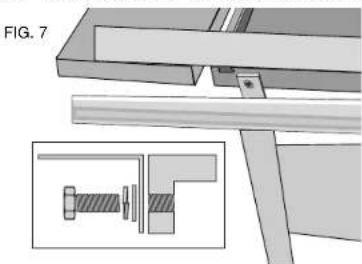
STEP 12. Attach left and right support tables (Fig. 7).
You will need: 6 - 10 x 25mm hex head bolts
6-10mm flat washers
6-10mm lock washers
Without the support table in place, install the 3 bolts per side with washers as shown keeping 1/4'' gap. Rest a support table on the bolts, fitting into the notches. Using the extruded fence face as a straightedge, flush the support table to the saw table edge and snug the front bolt. Repeat this process for the rear bolt and the center bolt. Tighten hardware. Repeat on the other side.
STEP 13. Attach front rail bracket to support tables (Fig 4).
You will need: 2 - 10 x 25mm flat head screws
2 - 10mm flat washers
2 - 10mm lock washers
2-10mm nuts
Align front bracket with support table and tighten bracket nut to the rail. Attach the support tables to the outer front rail support brackets, keeping the washers and nut on the inside of the table. Using the fence face as a straight edge, make sure the front outer corner of the support table is level with the inner edge and main table surface.
Tighten hardware, including the 8mm rail support bracket nut. Repeat this procedure for the other support table.
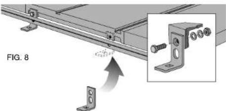
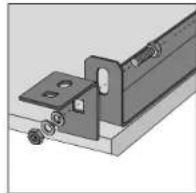
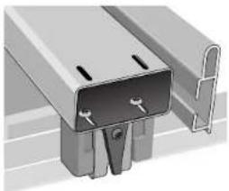
STEP 14. Attach hanger brackets to saw table (Fig. 8).
You will need: 2 - 10 x 35mm hex head bolts
2-10mm flat washers
2-10mm lock washers
2-10mm nuts
Secure a bolt through the square hole in each bracket with a flat washer, lock washer, and nut, keeping the washers and nuts to the inside of the table. When tightening nuts, keep the brackets positioned square to the table. (With another accessory in place, insure the hanger brackets are placed between the rear rail and the saw table.)
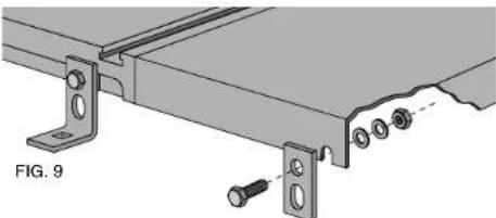
STEP 15. Attach two rear support brackets (Fig. 9). (With other accessories in place, rear support bracket(s) are not needed. The rear rail will attach directly to the accessory).
You will need: 2 - 10 x 25mm hex head bolts
2 - 10mm flat washers
2 - 10mm lock washers
2-10mm nuts
Secure a bolt through the round hole in each bracket with a flat washer, lock washer, and a nut, keeping the washers and nut to the inside. Make sure hardware is placed to the top of the slot in the rear of the support table(s) and tighten. When tightening, keep the brackets positioned square to the table.
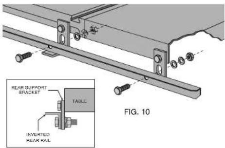
STEP 16. Position rear rail as shown and attach (Fig. 10).
You will need: 4 - 10 x 35mm hex head bolts
4-10mm flat washers
4-10mm lock washers
4-10mm nuts
STEP 17. Parallel the rear rail to the table top (Fig. 6). Using your fence face or a straightedge to extend the table surface over the rail, make sure the distance from the table top to the rail top is the same at both the left and right side of the table. If the rail is not aligned correctly, loosen the hardware slightly and tap on the rail with a soft hammer or a regular hammer and a block of wood until the distances are the same. Tighten the hardware securely. Repeat procedure to parallel rear rail to accessories (if applicable).
STEP 18. Parallel the rear rail to support table(s) (Fig.7). Using your fence face as a straightedge, make sure the rear outer corner of the support table is level with the inner edge and main table surface. Adjust if necessary and tighten hardware. Repeat this procedure for the other support table (if applicable).
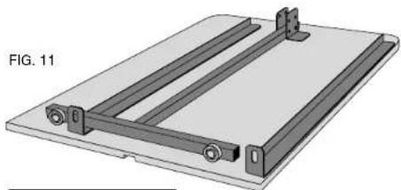
STEP 19. Assemble the outfeed table (Fig. 11).
You will need: 2 - 10 x 25mm hex head bolts
2-10mm flat washers
2-10mm lock washers
2-10mm nuts
Place the table on the floor, flat side down. Mount the two remaining hanger brackets using two M10 x 25 bolts. Secure each bolt through the square hole in the short leg of the bracket with a flat washer, lock washer, and nut (Fig 11). Tighten snug only.
STEP 20. Unfold the leg set by depressing the locking buttons on both sides and swinging the leg set upward until the locking buttons engage.
STEP 21. Place the outfeed table into position (Fig. 12).
You will need: 2 - 10mm carriage bolts
2-10mm wing nuts
Position table so the hanger brackets on the outfeed table are on top of the brackets on the table saw. Place the carriage bolts down through the square holes in the brackets and secure each with a wing nut. Tighten securely.
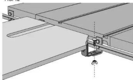
FIG. 12
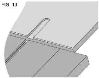
STEP 22. Check Outfeed Table miter clearance slot alignment. Place miter gauge into right hand miter slot in the saw table. Slide miter gauge beyond the rear of the saw table and into the clearance slot in the Outfeed Table top. Outfeed Table should not interfere with the smooth operation of the miter gauge. If necessary, loosen the M10 x 25 hardware (Fig. 13) holding the table to the hanger brackets and tap on the outfeed table with a soft hammer or a regular hammer and a block of wood until clearance slot is aligned.
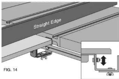
STEP 23. Parallel outfeed table to the table top. Outfeed table should be level with or slightly below the table top. For the edge closest to the table use your fence face or a straightedge to extend the saw table surface over the outfeed table. To align the tables tap on the outfeed table with a soft hammer or a regular hammer and a block of wood until they are parallel. Tighten the M10 X 25 hardware holding the outfeed table to the hanger brackets securely (Fig. 14). Using the adjustable feet on the bottom of the leg set, level the rear of the outfeed table to match its front edge.
STEP 24. See DW746 manual for Table Saw operating instruction and adjustments.
Additional Information
Removal and Storage:
- The outfeed table can be easily taken off by removing the carriage bolts and wing nuts. Remove the outfeed table from the back of the saw. Fold leg set down, locking into place, and table is ready for storage. Replace hardware into hanger brackets for safe keeping
Cleaning:
- The table board of your Outfeed table is a composite material, excessive moisture can cause deterioration. Cleaning with a damp cloth or a mild solvent on the top surface is acceptable, but the edges of the board should not be wetted.
Adjust the rear fence glide
If necessary, adjust the rear glide to locate it correctly against the rear rail by loosening the two screws which secure it to the fence beam. The plastic retaining clip should be deflected somewhat when the glide is positioned correctly. This adjustment should only be necessary if the rear rail has been relocated by the addition of an optional accessory.
A VERTISMENT : POUR VOITRE PROPRE SECURITE, LIsez LE GUIDE D'UTILISATION AVANT D'UTILISER LA SCIE • PORTEZ TOUJOURS DES LUNETTES DE PROTECTION DES YEUX • NE PORTEZ PAS DE GANTS, DE CRAVATE, DE BIJoux OU DE VETEMENTS AMPLES • ATTACHEZ VOS CHEVEux S'ILS SONT LONGS • GARDEZ VOS MAINS ET VOS DOIGTS HORS DU TRAJET DE LA LAME - FAITES EXTREMEMENT ATTENTION SI VOUS BISEAUTEZ • UTILISEZ TOUJOURS LE PROTECTEUR DE LA LAME ET L'EGARTEUR POUR TOUTE OPÉRATION POUR LAQUÉLLE IL PEUT ÉTRÉ UTILISÉ Y COMPRIS SCIER • UTILISEZ UN « POUSSOIR » AU BESOIN • SACHEZ EVITER LES REBONDS — VOIR LE GUIDE • SOUTENEZ TOUJOURS VOTRE TRAVAIL AVEC LA TABLE ET LE GUIDE OU LE CALIBRE À ONGLETS • N'UTILISZ JAMAIS LE GUIDE ET LE CALIBRE À ONGLETS ENSEMBLE • NE PASSEZ JAMAIS LA MAIN AUTOUR OU AU DESSUS DE LA LAME • MONTEZ BIEN LA LAME AVANT DE L'UTILISER • NE RETIREZ JAMAIS DES MORCEaux COINCÉS OU COUPÉS TANT QUE L'ALIMENTATION N'EST PAS ÉTÉINTE ET QUE LA LAME N'EST PAS ARRÉTÉE • N'EXPOSEZ PAS CET OUTIL À LA PLUÉE I AND NE L'UTILISEZ PAS DANS DES LIEUX HUMIDÉS • NE LE FAITES PAS FONCTIONNER EN CAS D'ÉTAT D'EBRIÉTÉ OU D'ÉTAT DROGUE • MANQUER DE RESPECTER CES CONSIGNES POT RÉSULTER DANS DES BLESSURES GRAVES.
AVENTISSEMENT: L'UTILISATION DE CET OUTFIL PEUT GENERER DES POUSSIÈRES CONTENANT DES PRODUITS CHIMIQUE S CONNUS POUR ÉTRE À L'ORIGINE DE CANCERS, DE MALFORMATIONS CONGENITALES OU AUTRES. ENDOMMAGEMENTS DU SYSTème REPRODUCTIF. UTILISEZ UN APPAREIL RESPIRATOIRE APPROPRIÉ.