
KFM 93 RF - Milling machine METABO - Free user manual and instructions
Find the device manual for free KFM 93 RF METABO in PDF.
| Product Type | Router / Edge Trimmer |
| Brand | Metabo |
| Model | KFM 93 RF |
| Usage | Edge routing on steel, stainless steel, aluminum (professional use) |
| No-load speed | 4500 - 11500 rpm, adjustable in 6 positions |
| Electronic system | VC: maintains almost constant speed under load |
| Chamfer height adjustment | In increments of 0.1 mm, max 3 mm per pass |
| Indexable inserts | Carbide, interchangeable (ref. 6.23560, 6.23561, 6.23562) |
| Parallel guide | Included, angle adjustable |
| Spindle lock | Yes, for insert change |
| Protections | Overload, restart, S-automatic safety stop |
| Dust filter | Removable, for dusty environments |
| Cleaning | Regularly clean the ventilation slots and the milling head |
| Safety | Goggles, hearing protection, dust mask, gloves |
| Spare parts | Indexable inserts, ball bearing wear ring |
| Repairs | By a qualified electrician, contact Metabo |
Frequently Asked Questions - KFM 93 RF METABO
User questions about KFM 93 RF METABO
0 question about this device. Answer the ones you know or ask your own.
Ask a new question about this device
Download the instructions for your Milling machine in PDF format for free! Find your manual KFM 93 RF - METABO and take your electronic device back in hand. On this page are published all the documents necessary for the use of your device. KFM 93 RF by METABO.
USER MANUAL KFM 93 RF METABO
KFM 9-3 RF KFM 18 LTX 3 RF

natural_image
Two metal angle motors with visible brand logos, no text or symbols on the motors themselves.
en Operating Instructions 4
fr Mode d'emploi 12
natural_image
Close-up of a hand holding a handheld device with a white arrow pointing to the component (no visible text or symbols) | KFM 18 LTX 3 RF Serial Number: 01754.. | KFM 9-3 RF Serial Number: 01751.. | |
| UV | 18 | - | |
| n min | -1 (rpm) | 7000 11500 | |
| P1 | W | -900 | |
| P2 | W | -470 | |
| I120V | A | - | 8.0 |
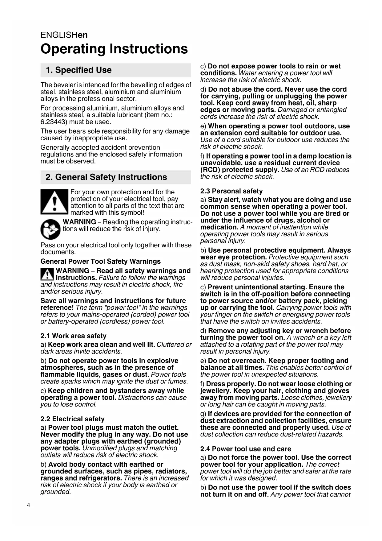
| hmax | in (mm) | 5/32 (4) 5/32 (4) | |
| rmax | in (mm) | 1/8 (3) 1/8 (3) | |
| a° | 45° 45° | ||
| m lbs (kg) | 6.4 (2,9) 5.5 (2,5) | ||
| ah/Kh | m/s2 | 0,94 / 1,5 0,7 / 1,5 | |
| LpA/KpA | dB(A) | 84 / 3 87 / 3 | |
| LWA/KWA | dB(A) | 95 / 3 98 / 3 | |
Metabowerke GmbH,
Postfach 1229
Metabo-Allee 1
D-72622 Nuertingen
Germany
ENGLISHen
Operating Instructions
1. Specified Use
The beveler is intended for the bevelling of edges of steel, stainless steel, aluminium and aluminium alloys in the professional sector.
For processing aluminium, aluminium alloys and stainless steel, a suitable lubricant (item no.: 6.23443) must be used.
The user bears sole responsibility for any damage caused by inappropriate use.
Generally accepted accident prevention regulations and the enclosed safety information must be observed.
2. General Safety Instructions

For your own protection and for the protection of your electrical tool, pay attention to all parts of the text that are marked with this symbol!

WARNING – Reading the operating instructions will reduce the risk of injury.
Pass on your electrical tool only together with these documents.
General Power Tool Safety Warnings

WARNING – Read all safety warnings and instructions. Failure to follow the warnings
and instructions may result in electric shock, fire and/or serious injury.
Save all warnings and instructions for future reference! The term "power tool" in the warnings refers to your mains-operated (corded) power tool or battery-operated (cordless) power tool.
2.1 Work area safety
a) Keep work area clean and well lit. Cluttered or dark areas invite accidents.
b) Do not operate power tools in explosive atmospheres, such as in the presence of flammable liquids, gases or dust. Power tools create sparks which may ignite the dust or fumes.
c) Keep children and bystanders away while operating a power tool. Distractions can cause you to lose control.
2.2 Electrical safety
a) Power tool plugs must match the outlet. Never modify the plug in any way. Do not use any adapter plugs with earthed (grounded) power tools. Unmodified plugs and matching outlets will reduce risk of electric shock.
b) Avoid body contact with earthed or grounded surfaces, such as pipes, radiators, ranges and refrigerators. There is an increased risk of electric shock if your body is earthed or grounded.
c) Do not expose power tools to rain or wet conditions. Water entering a power tool will increase the risk of electric shock.
d) Do not abuse the cord. Never use the cord for carrying, pulling or unplugging the power tool. Keep cord away from heat, oil, sharp edges or moving parts. Damaged or entangled cords increase the risk of electric shock.
e) When operating a power tool outdoors, use an extension cord suitable for outdoor use. Use of a cord suitable for outdoor use reduces the risk of electric shock.
f) If operating a power tool in a damp location is unavoidable, use a residual current device (RCD) protected supply. Use of an RCD reduces the risk of electric shock.
2.3 Personal safety
a) Stay alert, watch what you are doing and use common sense when operating a power tool. Do not use a power tool while you are tired or under the influence of drugs, alcohol or medication. A moment of inattention while operating power tools may result in serious personal injury.
b) Use personal protective equipment. Always wear eye protection. Protective equipment such as dust mask, non-skid safety shoes, hard hat, or hearing protection used for appropriate conditions will reduce personal injuries.
c) Prevent unintentional starting. Ensure the switch is in the off-position before connecting to power source and/or battery pack, picking up or carrying the tool. Carrying power tools with your finger on the switch or energising power tools that have the switch on invites accidents.
d) Remove any adjusting key or wrench before turning the power tool on. A wrench or a key left attached to a rotating part of the power tool may result in personal injury.
e) Do not overreach. Keep proper footing and balance at all times. This enables better control of the power tool in unexpected situations.
f) Dress properly. Do not wear loose clothing or jewellery. Keep your hair, clothing and gloves away from moving parts. Loose clothes, jewellery or long hair can be caught in moving parts.
g) If devices are provided for the connection of dust extraction and collection facilities, ensure these are connected and properly used. Use of dust collection can reduce dust-related hazards.
2.4 Power tool use and care
a) Do not force the power tool. Use the correct power tool for your application. The correct power tool will do the job better and safer at the rate for which it was designed.
b) Do not use the power tool if the switch does not turn it on and off. Any power tool that cannot
be controlled with the switch is dangerous and must be repaired.
c) Disconnect the plug from the power source and/or the battery pack from the power tool before making any adjustments, changing accessories, or storing power tools. Such preventive safety measures reduce the risk of starting the power tool accidentally.
d) Store idle power tools out of the reach of children and do not allow persons unfamiliar with the power tool or these instructions to operate the power tool. Power tools are dangerous in the hands of untrained users.
e) Maintain power tools. Check for misalignment or binding of moving parts, breakage of parts and any other condition that may affect the power tool's operation. If damaged, have the power tool repaired before use. Many accidents are caused by poorly maintained power tools.
f) Keep cutting tools sharp and clean. Properly maintained cutting tools with sharp cutting edges are less likely to bind and are easier to control.
g) Use the power tool, accessories and tool bits etc. in accordance with these instructions, taking into account the working conditions and the work to be performed. Use of the power tool for operations different from those intended could result in a hazardous situation.
2.5 Battery tool use and care
a) Recharge only with the charger specified by the manufacturer. A charger that is suitable for one type of battery pack may create a risk of fire when used with another battery pack.
b) Use power tools only with specifically designated battery packs. Use of any other battery packs may create a risk of injury and fire.
c) When battery pack is not in use, keep it away from other metal objects, like paper clips, coins, keys, nails, screws or other small metal objects, that can make a connection from one terminal to another. Shorting the battery terminals together may cause burns or a fire.
d) Under abusive conditions, liquid may be ejected from the battery; avoid contact. If contact accidentally occurs, flush with water. If liquid contacts eyes, additionally seek medical help. Liquid ejected from the battery may cause irritation or burns.
2.6 Service
a) Have your power tool serviced by a qualified repair person using only identical replacement parts. This will ensure that the safety of the power tool is maintained.
3. Special Safety Instructions
a) Do not use accessories that are not specifically designed and recommended for this power tool by the manufacturer. Just
because the accessory can be attached to your power tool, it does not assure safe operation.
b) Do not use damaged power tools. Before use, check the indexable inserts for chipping, cracks, or signs of severe wear and tear. If a power tool or accessory is dropped, inspect for damage or install an undamaged accessory.
c) User personal protective equipment. Depending on application, use face shield, safety goggles or safety glasses. As appropriate, wear dust mask, hearing protectors, gloves and workshop apron capable of stopping small abrasive or workpiece fragments. The eye protection must be capable of stopping flying debris generated by various operations. The dust mask or respirator must be capable of filtrating particles generated by your operation. Prolonged exposure to high intensity noise may cause hearing loss.
d) Keep bystanders a safe distance away from work area. Anyone entering the work area must wear personal protective equipment. Fragments of workpiece or of a broken accessory may fly away and cause injury beyond immediate area of operation.
e) Always hold the tool firmly in your hands during the start-up. The reaction torque of the motor, as it accelerates to full speed, can cause the tool to twist.
f) Use clamps to support workpiece whenever practical. Never hold a small workpiece in one hand and the tool in the other hand while in use. Clamping a small workpiece allows you to use your hands to control the tool.
g) Never lay the power tool down until the accessory has come to a complete stop. The spinning accessory may grab the surface and pull the power tool out of your control.
h) Do not run the power tool while carrying it at your side. Accidental contact with the spinning accessory could snag your clothing, pulling the accessory into your body.
i) Regularly clean the power tool's air vents. The motor's fan will draw the dust inside the housing and excessive accumulation of powdered metal may cause electrical hazards.
j) Do not operate the power tool near flammable materials. Sparks and hot chips can ignite these materials.
k) Do not use accessories that require liquid coolants. Using water or other liquid coolants may result in electrocution or shock.
3.1 Kickback and Related Warnings
Kickback is the sudden response to an accessory pinching or jamming while rotating. Pinching or snagging causes rapid stalling of the rotating accessory which in turn causes the uncontrolled power tool to be forced in the direction opposite of the accessory's rotation at the point of the binding.
For example, if an indexable insert is snagged or pinched by the workpiece, the edge of the insert that is entering into the pinch point can dig into the
ENGLISHen
surface of the material causing the insert to climb out or kick out. The indexable insert may either jump toward or away from the operator, depending on direction of the indexable insert holder at the point of pinching. Indexable inserts may also break under these conditions.
Kickback is the result of power tool misuse and/or incorrect operating procedures or conditions It can be prevented if suitable precautionary measures are taken as described below.
a) Maintain a firm grip on the power tool and position your body and arm to allow you to resist kickback forces. The operator can control kickback forces, if proper precautions are taken.
b) Use special care when working corners, sharp edges etc. Avoid bouncing and snagging the accessory. Corners, sharp edges or bouncing have a tendency to snag the rotating accessory and cause loss of control or kickback.
c) Always feed the bit into the material in the same direction as the cutting edge is exiting from the material (which is the same direction as the chips are thrown). Feeding the tool in the wrong direction causes the cutting edge of the bit to climb out of the work and pull the tool in the direction of this feed.
d) Prevent any jamming of the indexing insert or excessive pressure. Do not set the chamfer height greater than the permitted maximum.
Overstressing the indexable insert increases the loading and susceptibility to twisting or binding of the indexable insert in the cut and the possibility of kickback or breakage of the indexable insert.
e) Do not position your hand in line with and behind the indexable insert. When the indexable insert, at the point of operation, is moving away from your body, the possible kickback may propel the spinning indexable insert and the power tool directly at you.
Turn/replace blunt indexable inserts or inserts where the coating is worn in due time. Blunt indexable inserts increase the risk of the machine getting jammed and climb out.
3.2 Additional Safety Instructions:
Hold power tool by insulated gripping surfaces, because the cutter may contact its own cord. Cutting a “live” wire may make exposed metal parts of the power tool “live” and shock the operator.
Keep work area clean and well lit. Cluttered or dark areas invite accidents.
WARNING – Always wear protective goggles.
Wear ear protectors.
Wear a suitable dust protection mask.
Wear suitable work clothes.
Ensure that nobody gets injured by catapulted foreign bodies.
Keep persons nearby and pets at a safe distance to the device.
Keep away hair, loose clothing, fingers and other body parts. They can get caught and sucked in. Use a hair net for long hair.
Warning from rotating tools
Always wear protective goggles, gloves, and sturdy shoes when working with this tool.
Danger of injury from sharp edges. Wear protective gloves.
Indexable inserts, holders for indexable inserts, workpiece and chips can be hot after work. Wear protective gloves.
Wear ear protectors when working for long periods of time. High noise levels over a prolonged period of time may affect your hearing.
Use only sharp, undamaged indexable inserts.
The workpiece must lay flat and be secured against slipping, e.g. using clamps. Large workpieces must be sufficiently supported.
Ensure that sparks produced during work do not constitute a risk to the user or others and are not able to ignite flammable substances. Areas at risk must be protected with flame-resistant covers. Always keep a fire extinguisher on hand when working in areas prone to fire risk.
Always hold the machine with both hands on the intended handles, take a secure stance and concentrate on the work.
Keep your hands away from the milling area and from the tool.
Do not touch the rotating tool! Remove chips and similar material only with the machine at a standstill.
Press the spindle locking button (2) only when the motor is off.
Damaged, eccentric or vibrating tools must not be used.
Do not work overhead.
Reduce dust exposure:
Some dust created by using this power tool may contain chemicals known to cause cancer, allergic reaction, respiratory disease, birth defects or other reproductive harm. Some of these substances include: Lead (in paint containing lead), mineral dust (from bricks, concrete etc.), additives used for wood treatment (chromate, wood preservatives), some wood types (such as oak or beech dust), metals, asbestos.
The risk from exposure to such substances will depend on how long you or bystanders are being exposed.
Do not let particles enter the body.
Do the following to reduce exposure to these
substances: Ensure good ventilation of the workplace and wear appropriate protective equipment, such as respirators able to filter microscopically small particles.
Observe the relevant guidelines for your material, staff, application and place of application (e.g. occupational health and safety regulations, disposal).
Collect the generated particles at the source, avoid deposits in the surrounding area.
Reduce dust exposure with the following measures:
- Do not direct the escaping particles and the exhaust air stream at yourself or nearby persons or on dust deposits.
- Use an extraction unit and/or air purifiers
- Ensure good ventilation of the workplace and keep clean using a vacuum cleaner Sweeping or blowing stirs up dust
- Vacuum or wash the protective clothing Do not blow, beat or brush
3.3 Special safety instructions for mains powered machines:
Pull the plug out of the socket before making any adjustments, changing tools, carrying out maintenance or cleaning.
Use of a fixed extractor system is recommended. Always install an RCD (GFCI) with a maximum trip current of 30 mA upstream. When the machine is shut down by the RCD (GFCI), it must be checked and cleaned. See chapter 9. Cleaning.
3.4 Special safety instructions for cordless machines:
Remove the battery pack from the machine before making any adjustments, changing tools, maintaining or cleaning.

Protect battery packs from water and moisture!
Do not expose battery packs to fire!
Do not use faulty or deformed battery packs! Do not open battery packs! Do not touch contacts or short-circuit battery packs!

A slightly acidic, flammable fluid may leak from defective Li-ion battery packs!

If battery fluid leaks out and comes into contact with your skin, rinse immediately with plenty of water. If battery fluid leaks out
and comes into contact with your eyes, wash them with clean water and seek medical attention immediately!
3.5 Symbols on the tool

...... Class II Construction
V..... volts
A ......amperes
Hz ...... hertz
W ...... watts
\~ ......alternating current
==...... direct current
rpm .... revolutions per minute .../min..... revolutions per minute n ..... rated speed
4. Overview
See page 2.
1 Clamping screws
2 Spindle locking button
3 Additional handle
4 Slide switch
5 Handle
6 Speed adjustment wheel
7 Dust filter *
8 Electronic signal indicator *
9 Battery pack release button *
10 Capacity indicator button *
11 Capacity and signal indicator *
12 Battery pack *
13 Graduated collar
14 Adjusting ring
15 Scale
16 Knurled screw *
17 Ripping fence*
18 Support surface
19 Screw for fixing the ball bearing stationary seal ring
20 Ball bearing stationary seal ring
21 Indexable insert
22 Fastening screw
23 Holder for indexable insert
*equipment-specific
5. Commissioning
5.1 For mains powered machines only

Before plugging in, check that the rated mains voltage and mains frequency, as stated on the plate match your power supply.

Always install an RCD(GFCI) with a maximum trip current of 30 mA upstream.
5.2 For cordless machines only
Dust filter

Always fit the dust filter (7) if the surroundings are heavily polluted.

The machine heats up faster when the dust filter (7) is fitted. It is protected by the ronics system from overheating (see Section
To fit: See illustration A on page 2.
Fit the dust filter (7) as shown.
Removal: Holding the dust filter (7) at the edges, raise it slightly and then pull it downwards and remove.
Rotating battery pack
See illustration B on page 2.
The rear section of the machine can be rotated 270^ in 3 stages, thus allowing the machine's shape to be
ENGLISHen
adapted to the working conditions. Only operate the machine when it is in an engaged position.
Battery pack
Charge the battery pack (12) before use.
If performance diminishes, recharge the battery pack.
The ideal storage temperature is between 10°C and 30°C.
Li-Ion battery packs "Li-Power" have a capacity and signal indicator (11):
- Press the button (10), the LEDs indicate the charge level.
- If one LED is flashing, the battery pack is almost flat and must be recharged.
Removing and inserting the battery pack
Removal: Press the battery pack release (9) button and pull the battery pack (12) downwards.
Inserting: Slide in the battery pack (12) until it engages.
5.3 Install parallel guide/ripping fence
See illustration on page 2.
-
Place the parallel guide/ripping fence (17) as shown.
-
Screw knurled screw (16) into one of the threaded holes.
-
Set the parallel guide/ripping fence (17) by turning to the desired angle.
-
Firmly tighten the knurled screw (16).
6. Setting

Remove the battery pack from the machine / pull the plug out of the socket before making adjustments, changing tools, carrying out tenance or cleaning.

Indexable inserts, holders for indexable inserts, workpiece and chips can be hot after. Wear protective gloves.

Danger of crushing! Wear protective gloves.
6.1 Adjust scales (only when required)
The scales (13), (15) come with the correct settings from the factory. However, should they be adjusted, see chapter 8.3.
6.2 Set chamfer height
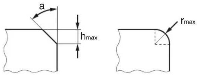
Read the set chamfer height at the graduated scale (13):
- Read the set chamfer height at the graduated scale (13). See illustration: Set chamfer height = 0.7 mm. (The scale (15) is used for the rough orientation during the setting process).
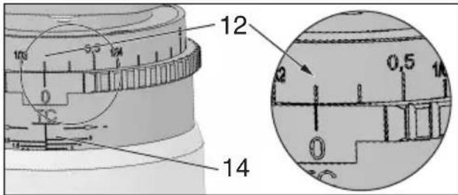
Change the chamfer height by turning the adjusting ring:
2. Push the adjusting ring (14) downwards and turn.
The chamfer height can be set in 0.1 mm (0.004") steps. Each full rotation results in a change of the chamfer height by 3.0 mm (1/8").

Remove max. 3.0 mm per cutting operation. Create larger chamfer heights in several
cutting operations. Do not exceed the maximum permitted chamfer height (see chapter Technical Specifications).
- Carry out trial cut.
7. Use
7.1 Switching On and Off

Always guide the machine with both hands.

Switch on first, then guide the accessory towards the workpiece.

Avoid unintentional start-up of the machine: always switch off the machine, if the plug is d from the mains socket or if there was a power if the battery pack was removed from the mine.

In continuous operation, the machine continues running if it is forced out of your s. Therefore, always hold the machine with hands using the handles provided, stand rely and concentrate.

Avoid the machine swirling up or taking in dust and chips. After switching off the machine, place it down when the motor has come to a Istill.
Machines with slide switch:
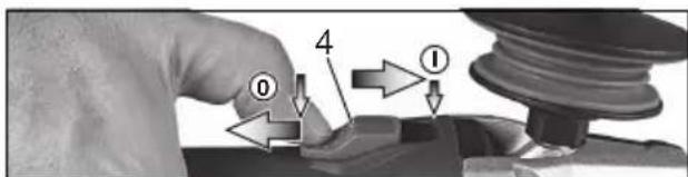
Switching on: Push the sliding switch (4) forward. For continuous activation, now tilt downwards until it engages.
Switching off: Press the rear end of the slide switch (4) and release it.
7.2 Setting speed
The speed can be preset via the thumb-wheel (6) and is infinitely variable.
Positions 1-6 correspond approximately to the following no-load speeds:
1.....4500 / min 4 .....9500 / min
2.....6200 / min 5 .....10800 / min
3.....8100 / min 6 .....11500 / min
The VC electronics make material-compatible work possible and an almost constant speed, even under load.
Speed recommendations for different materials:
Aluminium, copper, brass 4-6
Steel up to 400 N/mm2 4-6
Steel up to 600 N/mm2 3-5
Steel up to 900 N/mm2 2-4
Stainless steel....1-3
The best way to determine the ideal setting is through a practical trial.
7.3 Working Directions
- Check indexable inserts (21). Change damaged or worn indexable inserts.
- Set the chamfer height (see section 6.2).
- Always hold the machine with both hands on the intended handles, take a secure stance and concentrate on the work.
- First switch on, then place the machine with the support surface (18) onto the workpiece and only then put the tool close to the workpiece.
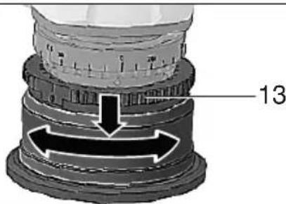
- When cutting, always work against the run of the disc (see illustration). Otherwise there is the risk of kickback. Cut with moderate material feed adapted to the material to be processed or selected speed. If the selected speed is too low and / or if the material feed is too high, strong vibrations can be caused (at the machine). Do not tilt, apply excessive force or sway from side to side.
- Guide the machine in such a way that the parallel guide (17) is in contact with the workpiece. If you work without parallel guide: Guide the machine in such a way that the ball-bearing stationary seal ring (20) is in contact with the workpiece.

natural_image
Simple diagram showing a sphere rolling down an inclined plane with directional arrows (no text or symbols)- To finish work: Remove the tool from the workpiece, switch off machine. Let motor come to a stop, put down machine.
8. Maintenance
8.1 Change indexable inserts
Regularly check the holder for the indexable inserts (23). Repair/replace damaged or worn holders for the indexable inserts.
Regularly check all indexable inserts (21). Change damaged or worn indexable inserts.
Remove the battery pack from the machine / pull the plug out of the socket before making any adjustments, changing tools, carrying out maintenance or cleaning.
Indexable inserts, holders for indexable inserts, workpiece and chips can be hot after work. Wear protective gloves.
Turn/replace blunt indexable inserts or inserts where the coating is worn in due time. Blunt indexable inserts increase the risk of the machine getting jammed and climb out.
Always turn or replace all indexable inserts.
Use only indexable inserts approved by Metabo. See the Accessories Section.
- By turning the adjustment ring (14) to the stop, unscrew the holder for the indexable inserts (23) as much as possible - this provides good access to the indexable inserts.
- Press in the spindle locking button (2) and turn the holder for the indexable inserts (14) by hand until the spindle locking button (2) engages. Keep the spindle locking button (2) pressed.
- Unscrew the fastening screw (22) and remove the indexable insert (21).
- Turn the indexable insert or, if all blades are blunt, replace the indexable inserts.
- Fix again the indexable inserts (21) with a fastening screw (22). Torque: 5 Nm.
- Turn the adjusting ring (14) in the opposite direction, so that the holder for the indexable inserts (23) is again in its normal work range. (So that the maximum permitted chamfer height is not exceeded, see chapter Technical Specifications).
8.2 Replace ball bearing stationary seal ring (only if required):
Regularly check the ball bearing stationary seal ring (20) for smooth running. Replace defective ball bearing stationary seal ring. (order no.: 316093300)
- Remove screw (19) and remove ball bearing stationary seal ring.
- Put new ball bearing stationary seal ring (20) in place and add screw (19), tighten firmly.
8.3 Adjust scale (only if required):
The graduated ring (13) comes properly set from the factory.
If indexable inserts are to be used for radii or if the settings should have been misaligned, the scale has to be adjusted as follows:
ENGLISHen
- Lift the adjustment ring (14) and turn in such a way that the indexable insert (21) does not remove any material. (chamfer height = 0 mm)
- Loosen the two clamping screws (13).
- Turn the graduated ring (13) until the chamfer height 0 mm is shown.
- Tighten the two clamping screws (13).
- Carry out trial cut.
9. Cleaning
Chips and particles can deposit at the cutter head. This can lead to blockage of the cutter head. Regularly clean the cutter head and its surroundings and remove chips and particles.
It is possible that particles deposit inside the power tool during operation. This impairs the cooling of the power tool. Conductive build-up can impair the protective insulation of the power tool and cause electrical hazards.
The power tool should be cleaned regularly, often and thoroughly through all front and rear air vents using a vacuum cleaner or by blowing in dry air. Prior to this operation, separate the power tool from the power source and wear protective glasses and dust mask.
10. Troubleshooting
10.1 Mains powered machines:
- Overload protection: There is a MAJOR reduction in load speed. The motor temperature is too high! Allow the machine to run at idle speed until it has cooled down.
- Overload protection: There is a MINOR reduction in load speed. The machine is overloaded. Reduce the load before continuing to work.
- Metabo S-automatic safety shut-down: The machine has SHUT DOWN by itself. If the slew rate of the current is too high (for example, if the machine suddenly seizes or kickback occurs), the machine switches off. Switch off the machine using the slide switch (4). Switch it on again and continue to work as normal. Try to prevent the machine from seizing. See chapter 3.1.
- Restart protection: The machine does not start. The restart protection is active. If the mains plug is inserted with the machine switched on, or if the power supply is restored following an interruption, the machine does not start up. Switch the machine off and on again.
10.2 Cordless machines:
- The electronic signal display (8) lights up and the load speed decreases. The temperature is too high! Run the machine in idling until the electronics signal indicator switches off.
- The electronic signal display (8) flashes and the machine does not start. The restart protection is active. The machine will not start if the battery pack is inserted while the machine is on. Switch the machine off and on again.
11. Accessories
Use only genuine Metabo accessories.
Use only accessories which fulfil the requirements and specifications listed in these operating instructions.
Fit accessories securely. If the machine is operated in a holder: Secure the machine well. Loss of control can cause personal injury.
A Indexable inserts
HM-indexable insert 45° 6.23560
HM-indexable insert R 2 6.23561
HM-indexable insert R 3 6.23562
B Chargers: ASC Ultra, ASC 15, ASC 30 and others
C Battery packs with different capacities. Use battery packs only with voltage suitable for your power tool.
For a complete range of accessories, see www.metabo.com or the catalogue.
12. Repairs

Repairs to electrical tools must ONLY be carried out by qualified electricians!
Contact your local Metabo representative if you have Metabo power tools requiring repairs. See www.metabo.com for addresses.
You can download a list of spare parts from www.metabo.com.
13. Environmental Protection
Observe national regulations on environmentally compatible disposal and on the recycling of disused machines, packaging and accessories.
Special notes regarding cordless machines:
Battery packs may not be disposed of with regular waste. Return faulty or used battery packs to your Metabo dealer!
Do not allow battery packs to come into contact with water!
Before disposal, discharge the battery pack in the power tool. Prevent the contacts from short-circuiting (e.g. by protecting them with adhesive tape).
14. Technical Data
Explanatory notes on the specifications on page 3. Changes due to technological progress reserved.
U = Voltage of battery pack
n = no-load speed (maximum speed)
n_1 =On-load speed
P_1 = Rated input power
P_2 =Power output
I_120V =Current at 120 V
m=Weight with smallest battery pack/weight without cord
The technical specifications quoted are subject to tolerances (in compliance with the relevant valid standards).

Emission values
These values make it possible to assess the emissions from the power tool and to compare different power tools. The actual load may be higher or lower depending on the operating conditions, the condition of the power tool or the accessories. Please allow for breaks and periods when the load is lower for assessment purposes. Arrange protective measures for the user e.g. organisational measures based on the adjusted estimates.
Vibration total value (vector sum of three directions) determined in accordance with EN 60745:
$$ \begin{array}{r l} {a _ {h, S G}} & {= \text {Vibration emission value}} \ {K _ {h, S G}} & {= \text {Uncertainty (vibration)}} \end{array} $$
Typical A-effective perceived sound levels:
$$ \begin{array}{l} L _ {p A} = \text { sound - pressure level } \ L _ {W A} = \text { Acoustic power level } \ K _ {p A}, K _ {W A} = \text { Uncertainty } \ \end{array} $$
During operation the noise level can exceed 80 dB(A).

Wear ear protectors!
Problems, faults:
In individual cases, the speed may fluctuate temporarily if the machine is exposed to extreme external electromagnetic disturbances or the electronic restart protection may respond. In this case, switch the machine off and on again.
FRANÇAISfr
Mode d'emploi
Voir page 2, figure B.
natural_image
Simple diagram showing a sphere rolling down an inclined plane with directional arrows (no text or symbols)K_h,SG =incertitude (vibration)
21 Plaquita reversible
natural_image
Simple diagram showing a sphere rolling down an inclined plane with directional arrows (no text or symbols)


- KFM 9-3 RF KFM 18 LTX 3 RF
- ENGLISHen
- Operating Instructions
- Specified Use
- General Safety Instructions
- General Power Tool Safety Warnings
- Work area safety
- Electrical safety
- Personal safety
- Power tool use and care
- Battery tool use and care
- Service
- Special Safety Instructions
- Kickback and Related Warnings
- Additional Safety Instructions:
- Wear ear protectors when working for long periods of time. High noise levels over a prolonged period of time may affect your hearing.
- Reduce dust exposure:
- Special safety instructions for mains powered machines:
- Special safety instructions for cordless machines:
- Symbols on the tool
- Overview
- See page 2.
- Commissioning
- For mains powered machines only
- For cordless machines only
- Dust filter
- Rotating battery pack
- Battery pack
- Removing and inserting the battery pack
- Install parallel guide/ripping fence
- Setting
- Adjust scales (only when required)
- Set chamfer height
- Read the set chamfer height at the graduated scale (13):
- Push the adjusting ring (14) downwards and turn.
- Use
- Switching On and Off
- Machines with slide switch:
- Setting speed
- Working Directions
- Maintenance
- Change indexable inserts
- Replace ball bearing stationary seal ring (only if required):
- Adjust scale (only if required):
- Cleaning
- Troubleshooting
- Mains powered machines:
- Cordless machines:
- Accessories
- Repairs
- Environmental Protection
- Special notes regarding cordless machines:
- Technical Data
- Emission values
- Wear ear protectors!
- Problems, faults:
- FRANÇAISfr
- Mode d'emploi
Brand : METABO
Model : KFM 93 RF
Category : Milling machine