
BRCH900 - Camcorder SONY - Free user manual and instructions
Find the device manual for free BRCH900 SONY in PDF.
| Product Type | HD PTZ (pan/tilt/zoom) video camera |
| Brand | Sony |
| Model | BRC-H900 |
| Sensor | 3-CMOS Exmor 1/2-type, 2.07 effective megapixels |
| Lens | 14x optical zoom, f=5.8–81.2 mm (35 mm equivalent: 31.4–439 mm), F1.9–F16 |
| Video Formats | 1080/59.94i, 1080/50i, 720/59.94p, 720/50p (switchable) |
| Video Outputs | HD/SD-SDI (BNC), composite (BNC), S-Video (mini-DIN), YPbPr/RGB (D-sub 15) |
| Pan Range | ±170° |
| Tilt Range | +90° (up) / -30° (down) |
| Pan/Tilt Speed | 0.22°/s to 60°/s |
| Minimum Illumination | 4 lux (F1.9, 50 IRE) |
| Signal-to-Noise Ratio | 50 dB (typ.) |
| Control | VISCA RS-232C/RS-422, supplied infrared remote control, optional RM-BR300 |
| Power Supply | 12 V DC (via supplied AC adapter), max. consumption 2.4 A (28.8 W) |
| Dimensions (W×H×D) | 198 × 260 × 238 mm (without protrusions) |
| Weight | Approx. 5.0 kg (camera only) |
| Supplied Accessories | AC adapter, power cord, remote control, ceiling mounts, wire rope, RS-422 connector |
| Operating Temperature | 0 °C to 40 °C |
| Cleaning | Blower brush for lens; soft dry cloth for body |
| Safety | Do not expose to rain or moisture. Refer servicing to qualified personnel. |
Frequently Asked Questions - BRCH900 SONY
User questions about BRCH900 SONY
0 question about this device. Answer the ones you know or ask your own.
Ask a new question about this device
Download the instructions for your Camcorder in PDF format for free! Find your manual BRCH900 - SONY and take your electronic device back in hand. On this page are published all the documents necessary for the use of your device. BRCH900 by SONY.
USER MANUAL BRCH900 SONY
For the customers in the U.S.A.
SONY LIMITED WARRANTY - Please visit http://www.sony.com/psa/warranty for important information and complete terms and conditions of Sony's limited warranty applicable to this product.
For the customers in Canada
SONY LIMITED WARRANTY - Please visit http://www.sonybiz.ca/pro/lang/entca/article/resources-warranty-for-important-information-and-complete-terms-and-conditions of Sony's limited warranty applicable to this product.
For the customers in Europe
Sony Professional Solutions Europe - Standard Warranty and Exceptions on Standard Warranty. Please visit http://www.pro.sony.eu/warrantyfor important information and complete terms and conditions.
For the customers in Korea
SONY LIMITED WARRANTY - Please visit http://bpeng.sony.co.kr/handle/BPAS-Start for important information and complete terms and conditions of Sony's limited warranty applicable to this product.
Sony Corporation Printed in Japan
SONY®
4-122-803-15(*)
HD Color Video Camera
Operating Instructions
GB
Mode d'emploi
FR
© 2012 Sony Corporation

4422803150
Before operating the unit, please read this manual thoroughly and retain it for future reference.
Owner's Record
The model and serial numbers are located on the bottom. Record these numbers in the spaces provided below. Refer to these numbers whenever you call upon your Sony dealer regarding this product.
Model No. BRC-H900
Serial No. ____
WARNING
To reduce the risk of fire or electric shock, do not expose this apparatus to rain or moisture.
To avoid electrical shock, do not open the cabinet. Refer servicing to qualified personnel only.
(For Installers only)
Instruction for installing the equipment on the ceiling: After the installation, ensure the connection is capable of supporting four times the weight of the equipment downwards.
IMPORTANT
The nameplate is located on the bottom.
For the customers in the U.S.A.
This equipment has been tested and found to comply with the limits for a Class A digital device, pursuant to part 15 of the FCC Rules. These limits are designed to provide reasonable protection against harmful interference when the equipment is operated in a commercial environment. This equipment generates, uses, and can radiate radio frequency energy and, if not installed and used in accordance with the instruction manual, may cause harmful interference to radio communications. Operation of this equipment in a residential area is likely to cause harmful interference in which case the user will be required to correct the interference at his own expense.
You are cautioned that any changes or modifications not expressly approved in this manual could void your authority to operate this equipment.
All interface cables used to connect peripherals must be shielded in order to comply with the limits for a digital device pursuant to Subpart B of part 15 of FCC Rules.
This device complies with part 15 of the FCC Rules. Operation is subject to the following two conditions: (1) This device may not cause harmful interference, and (2) this device must accept any interference received,
including interference that may cause undesired operation.
For the customers in Canada CAN ICES-3 (A)/NMB-3(A)
For the customers in Europe, Australia and New Zealand
WARNING
This is a Class A product. In a domestic environment, this product may cause radio interference in which case the user may be required to take adequate measures. In the case that interference should occur, consult your nearest authorized Sony service facility.
For the customers in Europe
Manufacturer: Sony Corporation, 1-7-1 Konan Minatoku Tokyo, 108-0075 Japan For EU product compliance: Sony Belgium, bijkantoor van Sony Europe Limited, Da Vincilaan 7-D1, 1935 Zaventem, Belgium
This apparatus shall not be used in the residential area.
ATTENTION
The electromagnetic fields at the specific frequencies may influence the picture of this unit.
Notice for CCFC-S200 Optical Fiber Cable
Only trained and qualified personnel should be allowed to install this equipment with the cable.
WARNING :
The cable is rated flammability class VW-1 and may be for indoor use only in some countries. Use appropriate alternative cables in accordance with the regulations and laws for each country taking the application and environment into account.
WARNING FOR THE AC ADAPTOR
This unit has no power switch.
When installing the unit, incorporate a readily accessible disconnect device in the fixed wiring, or connect the power plug to an easily accessible socket-outlet near the unit.
If a fault should occur during operation of the unit, operate the disconnect device to switch the power supply off, or disconnect the power plug.
AVERTISSEMENT
Supplied Components and Accessories 9
Optional Products 10
System Configuration 12
Operating a BRC-H900 Camera Using the Supplied Remote Commander .... 12
Operating a BRC-H900 Camera Using the RM-BR300 Remote Control Unit 12
Operating Multiple BRC-H900 Cameras Using the RM-BR300 Remote Control Unit .... 13
Operating a BRC-H900 Camera from a Long Distance 14
Operating Multiple BRC-H900 Cameras from a Long Distance 15
Operating Multiple BRC-H900 Cameras from Short and Long Distance 16
Transmitting Audio Signals Using the BRU-SF10 17
Location and Function of Parts .... 18
Camera 18
Remote Commander (supplied) 20
RM-BR300 Remote Control Unit (not supplied) 22
BRU-SF10 HD Optical Multiplex Unit (not supplied) 25
BRBK-SF1 HD Optical Multiplex Card (not supplied) 27
BRBK-HSD2 HD/SD-SDI Output Card (not supplied) 27
BRBK-SA1 Analog SD Output Card (not supplied) 28
Adjusting and Setting With Menus
About On-Screen Menus 29
Main Menu 29
Setting Menus 29
Operation Through Menus 30
Menu Operation Using the Supplied Remote Commander 30
Menu Operation Using the RM-BR300 Remote Control Unit ....31
EXPOSURE Menu ....32
COLOR Menu ....33
DETAIL Menu 34
COLOR DETAIL Menu 35
KNEE Menu 36
GAMMA Menu ....36
FLICKER CANCEL Menu ....37
FOCUS Menu ....38
PAN TILT Menu 39
SYSTEM Menu ....40
VIDEO OUT Menu 42
SD-SDI Menu 43
SD Menu 44
Operation Using the Supplied Remote Commander
Turning on the Power 45
Pan/Tilt and Zoom Operation ....45
Panning and Tilting 45
Zooming 46
Operating Multiple Cameras with the Remote Commander ....46
Adjusting the Camera 47
Focusing on a Subject 47
Shooting with Back Lighting ....47
Storing the Camera Settings in Memory
- Presetting Feature ....48
Operation Using the RM-BR300 Remote Control Unit
Turning on the Power 49
Operating Multiple Cameras ....49
Pan/Tilt and Zoom Operation ....50
Panning and Tilting 50
Zooming 52
Adjusting the Camera 52
Focusing on a Subject 52
Shooting with Back Lighting ....53
Adjusting the White Balance ....53
Adjusting the Brightness 53
Storing the Camera Settings in Memory
- Presetting Feature ....54
Storing Camera Settings ....54
Setting the Speed of the Camera Movement to a Preset Position ....55
Installation and Connections
Installation 56
Attaching an Interface Card 56
Installing the Camera ....57
Installing the Camera in a High Position ..... 57
Connections 64
Connecting to an AC Outlet 64
Connecting the RM-BR300 Remote Control Unit 65
Connecting a Monitor, etc., Equipped with the Analog Component (YPbPr) Input Connector 66
Connecting a Device Equipped with VISCA RS-232C Connector 66
Connecting a Device Equipped with VISCA RS-422 Connector ....67
Connecting a Video Monitor Equipped with Composite Video or S Video Input Connector 68
Connecting a Video Monitor, VTR, etc., Equipped with SDI Input Connector ....68
Connecting a VTR Equipped with HD-SDI Input Connectors 69
Connecting the BRU-SF10 HD Optical Multiplex Unit 69
Connecting a Video Switcher 71
Connecting a Sync Signal Generator 71
Appendix
List of Messages 73
Troubleshooting 74
Menu Configuration 76
Presetting Items 79
Specifications 81
Dimensions 83
Pin Assignments 86
Wiring Diagram of VISCA RS-422 Connection 89
Using the VISCA RS-422 Connector Plug ..... 90
Getting Started
Precautions
Operating or storage location
- Operating or storing the camera in the following locations may cause damage to the camera:
- Extremely hot or cold places (Operating temperature: 0^ to 40^ [32 °F to 104 °F])
- Exposed to direct sunlight, or close to hot equipment (e.g., near heaters)
- Close to sources of strong magnetism
- Close to sources of powerful electromagnetic radiation, such as radios or TV transmitters
– Locations subject to strong vibration or shock - Use of a mobile phone close to this camera may cause a malfunction of the camera or affect the quality of images. You are cautioned to turn off any mobile phone near the camera.
- Never expose the lens to the sun or other strong light source.
Exposing the lens to the sun or other strong light source may cause damage to internal parts. When the camera is not being used, keep it out of direct sunlight and other strong light, or protect it with a lens cover.
Ventilation
To prevent heat buildup, do not block air circulation around the camera.
Transportation
When transporting the camera, repack it as originally packed at the factory or in materials equal in quality.
Cleaning
- Use a blower to remove dust from the lens or optical filter.
- Use a soft, dry cloth to clean the external surfaces of the camera. Stubborn stains can be removed using a soft cloth dampened with a small quantity of detergent solution, then wipe dry.
- Do not use volatile solvents such as alcohol, benzene or thinners as they may damage the surface finishes.
The pan/tilt mechanism
Do not disturb pan/tilt movement while power is supplied to the camera. Doing so may cause damage or malfunction.
Do not touch the camera casing, the lens, or any part of the camera, when energized. It may cause a malfunction of the camera.
Maintenance
The camera mechanism may cause abnormal noise due to wear and lubrication loss after a long period of use. To maintain optimum performance, we recommend periodic maintenance. If abnormal noise occurs, consult your Sony dealer.
Camera function setting
Before setting the function of the camera such as pan/tilt, angle of view, zooming, etc., install the camera suitably and fix the camera securely. If you change the camera's installation after setting functions, differences may arise on the setting.
Recording an image
Make sure that the image is displayed correctly. If the image is not displayed correctly (the image is distorted, etc.), turn the camera off, then on again.
Note on laser beams
Laser beams may damage a CMOS image sensor. You are cautioned that the surface of a CMOS image sensor should not be exposed to laser beam radiation in an environment where a laser beam device is used.
Phenomena Specific to CMOS Image Sensors
The following phenomena that may appear in images are specific to CMOS (Complementary Metal Oxide Semiconductor) image sensors. They do not indicate malfunctions.
White flecks
Although the CMOS image sensors are produced with high-precision technologies, fine white flecks may be generated on the screen in rare cases, caused by cosmic rays, etc. This is related to the principle of CMOS image sensors and is not a malfunction.
The white flecks especially tend to be seen in the following cases:
- when operating at a high ambient temperature
- when you have raised the gain (sensitivity)
The white flecks may be reduced by turning the camera off, then on again.
Aliasing
When fine patterns, stripes, or lines are shot, they may appear jagged or flicker.
Focal plane
Owing to the characteristics of the pickup elements (CMOS image sensors) for reading video signals, subjects that quickly move across the screen may appear slightly skewed.
Flash band
If you shoot a strobe or quick-flashing light, brightness may differ between the upper and lower halves of the picture.
Flicker
If recording under lighting produced by discharge tubes, such as fluorescent, sodium, or mercury-vapor lamps, the screen may flicker, colors may vary, or horizontal stripes may appear distorted. In such cases, turn the FLICKER CANCEL function on (see page 37).
Depending on lighting types, etc., such phenomena may not be improved with the FLICKER CANCEL function. It is recommend to set the shutter speed to 1/100 sec. in the areas of 50 Hz power supply frequency and to 1/60 in the areas of 60 Hz.
Overview
Features
Compact, HD 3CMOS video camera with built-in pan/tilt/zoom functions
- This HD 3CMOS video camera integrates a camera block equipped with three 1/2-type Exmor CMOS sensors, a pan/tilt mechanism, and a 14-magnification optical zoom lens in a compact body. The compactness and integration allow versatile usage of the camera.
- The camera is provided with a wide-angle pan/tilt mechanism of ± 170^ horizontally, 90^ upward and 30^ downward, which enables wide-range remote shooting.
- The pan/tilt mechanism enabling smooth camera movement even at low speed, realizes a minimum pan/tilt speed of 0.22^ per second.
- The pan/tilt mechanism is remarkably quiet, even at the maximum pan/tilt speed of 60^ per second.
HD CMOS camera with high image quality and high-resolution remote shooting
- The 3CMOS camera system that incorporates 1/2-type CMOS image sensors with a total of 2,070,000 (1920 × 1080) picture elements allows the shooting of high-definition images, providing superior picture quality with high sensitivity and lower smear level.
- Shooting an image using the 1080i (effective interlaced scanning: 1080 lines) high-definition format, which is equivalent to the HDTV broadcast, is enabled. The HD format can be switched (1080/59.94i or 1080/50i) with the switch at the bottom of the camera.
- A volume of information four times the capacity of a normal TV broadcast and camera image shot in 16:9 aspect ratio provides a theater-like wide screen picture.
Compatible with HD multi-format output
- The camera is compatible with the 720p (effective interlaced scanning: 720 lines) format in addition to the 1080i format. You can select the format by the switch on the bottom of the camera. You can also switch between 720/59.94p format and 720/50p format by the switch on the bottom of the camera.
Built-in HD/SD-SDI output
- SDI output is available without inserting an optional Interface Card. By operating the switch on the camera, you can output an HD-SDI signal conforming to SMPTE 292 serial digital interface standards, or output an SD-SDI signal conforming to SMPTE 259M serial digital interface standards.
Built-in down-converted output
The camera is equipped with video output connectors, allowing HD ^1) or SD ^2) output without inserting an Interface Card. You can use the connectors for SD output now and for HD output in the future.
1) “HD” indicates high-definition broadcast with 1,080 or 720 effective scanning lines.
2) “SD” indicates standard-definition broadcast (conventional television).
Built-in interface card slot
The camera is equipped with an interface card slot for the optional BRBK-SF1 HD Optical Multiplex Card, BRBK-HSD2 HD/SD-SDI Output Card, and BRBK-SA1 Analog SD Output Card. Use of these Interface Cards gives the camera the capability of having versatile image output formats.
Long-distance image transmission and pan/tilt/zoom control
- Combined use of the BRBK-SF1 HD Optical Multiplex Card, CCFC-S200 Optical Fiber Cable and BRU-SF10 Optical Multiplex Unit, and Sony unique camera connection technology and optical digital multiplex transmission technology, allows a long distance transmission of camera images up to 2,000 m (6,562 feet) and pan/tilt/zoom control signals. Use of the optical fiber cable enables an economical and easy system configuration for long distance.
- The supplied ceiling brackets allow installation of the camera on a ceiling or a shelf, etc., in a high position.
VISCA camera protocol supported
- The camera is equipped with both RS-232C and RS-422 communication interfaces. As the camera supports the industry-standard VISCA camera protocol, up to seven cameras can be connected and remotely controlled at a high communication speed of 38,400 bps.
- The optional RM-BR300 Remote Control Unit allows easy camera operations.
Compatible with VISCA over IP protocol
By inserting the BRBK-IP10 IP control card to this unit, you can make an IP connection between this unit and RM-IP10 IP Remote Controller.
When the IP connection is made, you can operate up to 112 cameras by using RM-IP10.
For details about necessary devices or functions for IP connection, see “Operation Guide for Optional IP Control.”
External video sync function
The camera is equipped with an external video sync function to synchronize the camera images on multiple cameras. The camera also has an analog component/RGB output connector as standard equipment.
Tally lamp
The tally lamp of the camera allows you to make sure it is selected at a glance. The tally lamp on the front side of the camera is large, enabling good visual recognition. Also, the tally lamp on the rear side of the camera enables good visual recognition from behind the camera.
System Components
In order to support multiple system configurations, a variety of optional products are available for the BRC-H900 HD Color Video Camera. This section introduces these optional products as well as the accessories supplied with the camera.
Supplied Components and Accessories
Before using the camera, make sure you have the following components and accessories supplied.
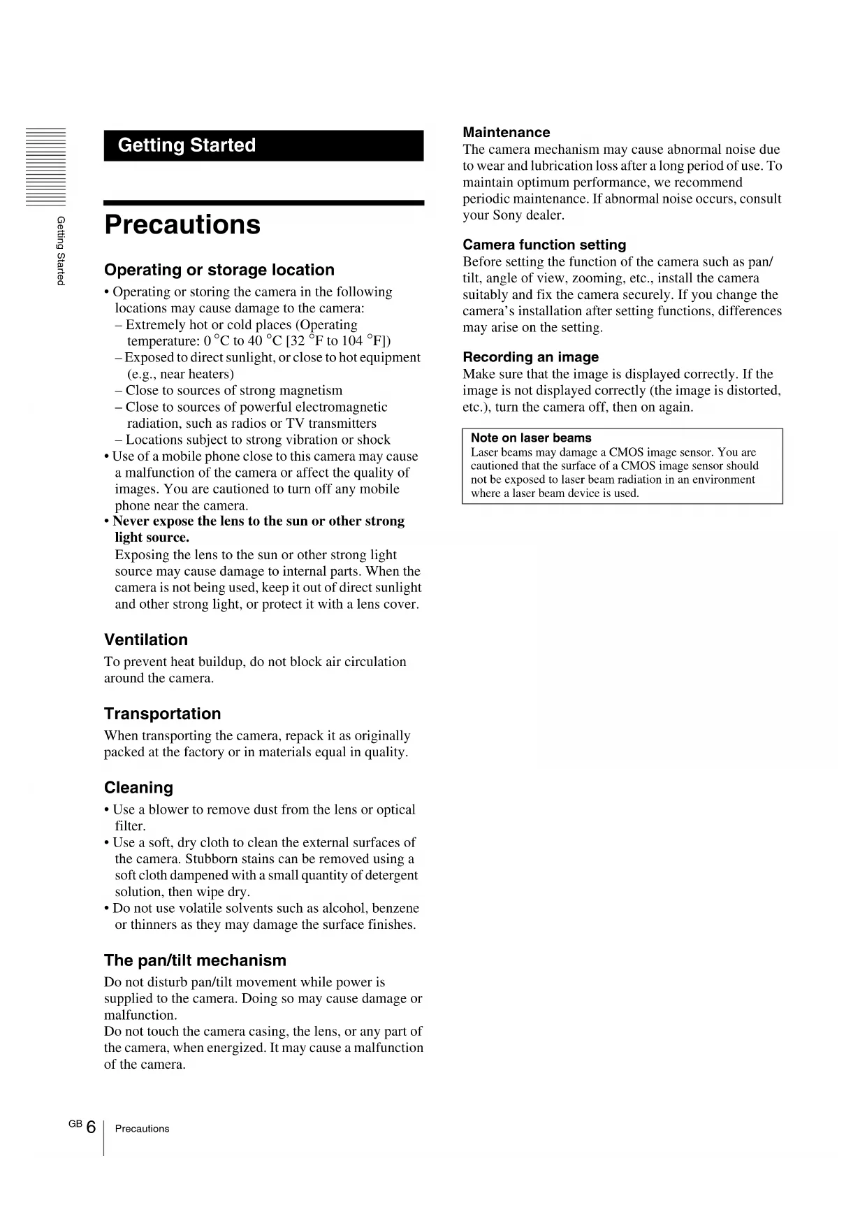
Camera (1)
natural_image
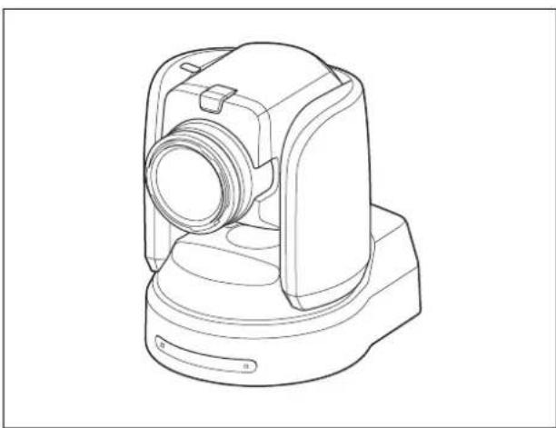
Line drawing of a mechanical device with no visible text or symbolsAC power adaptor (Sony) (1)
natural_image
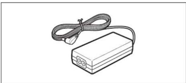
Line drawing of a rectangular electronic device with coiled cable and connector (no text or symbols)AC power cord (1)
USA and Canadian model
natural_image
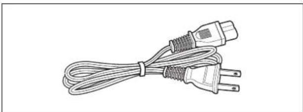
Line drawing of a cord with two connected power plugs (no text or symbols)
European model
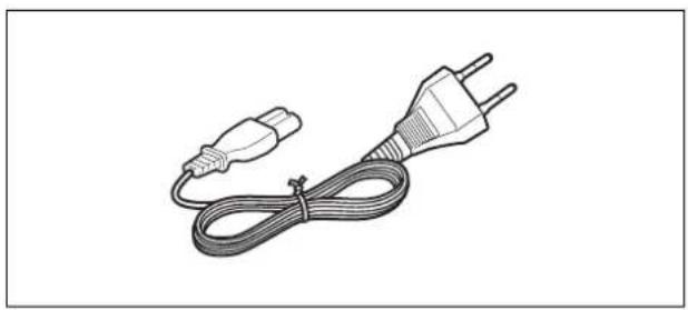
natural_image
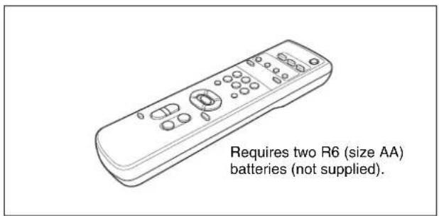
Line drawing of a plug and cable with two leads (no text or symbols)Remote commander (1)
Ceiling bracket (A) (1)
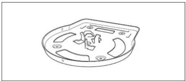
natural_image
Technical line drawing of a mechanical component with cutouts and mounting holes (no text or symbols)Ceiling bracket (B) (1)
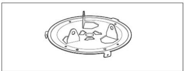
natural_image
Technical line drawing of a circular mechanical component with four symmetrical cutouts and mounting holes (no text or symbols)Wire rope (1)
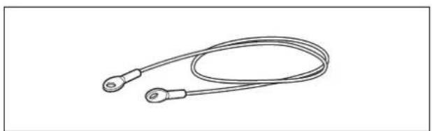
natural_image
Line drawing of a coiled cable or wire with two terminal connectors (no text or symbols)Screw ⊕M3 × 8 (7)/Stainless screw ⊕M4 × 8 (1)

natural_image
Two identical mechanical screw or nut diagrams with threaded ends, shown from different angles (no text or symbols)RS-422 connector plug (1)

natural_image
Isometric line drawing of a connector pinout (no text or symbols)DC-cord secure connection attachment (1)

natural_image
Simple line drawing of a 3D mechanical bracket or bracket (no text or symbols)Operating Instructions (1)
Optional Products
RM-BR300 Remote Control Unit
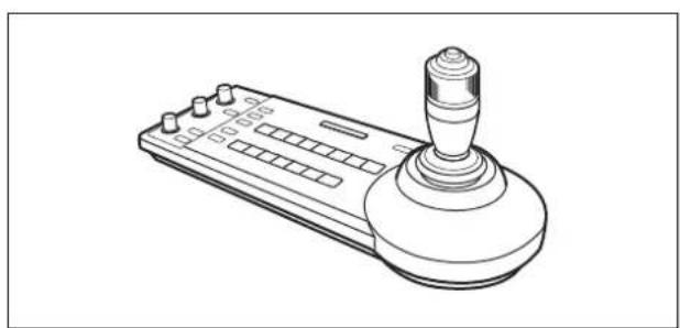
natural_image
Line drawing of a joystick controller with handle and control panel (no text or symbols)The joystick of the Remote Control Unit allows you comfortable pan/tilt and zoom operations. The Remote Control Unit also allows remote operation of up to seven cameras.
Supplied accessories: AC adaptor (1), AC power cord (1), RS-232C connecting cable (3 m (9.8 feet)) (1), RS-422 connector plug (2)
BRBK-SF1 HD Optical Multiplex Card
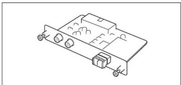
natural_image
Isometric line drawing of an electronic device with ports and connectors (no text or symbols)Insert the card into the camera to allow high-bit multiplex transfer via optical fiber cable (video, audio, external video sync and control signals).
BRBK-HSD2 HD/SD-SDI Output Card
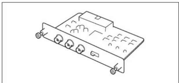
natural_image
Line drawing of a multi-pin electronic device chassis with ports and connectors (no text or symbols)Insert the card into the camera to allow output of an HD-SDI signal conforming to SMPTE 292 serial digital interface standards, or output of an SD-SDI signal conforming to SMPTE 259M serial digital interface standards. An audio signal is not output from the card.
BRBK-SA1 Analog SD Output Card
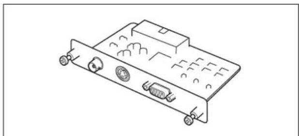
natural_image
Line drawing of an electronic device rear panel with ports and connectors (no text or symbols)Insert the card into the camera to allow output of various SD analog signals such as composite video, S video, component video, and RGB signals.
BRU-SF10 HD Optical Multiplex Unit
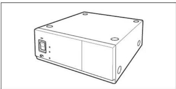
natural_image
Line drawing of a rectangular electronic device casing with mounting holes and a central control panel (no text or symbols)The HD Optical Multiplex Unit allows a connection of up to 2,000 m (6,562 feet) using the CCFC-S200 2-core optical fiber cable.
Supplied accessories: AC adaptor (1), AC power cord (1), DC-cord secure connection attachment (1), RS-232C connecting cable (3 m (9.8 feet)) (1), RS-422 connector plug (1)
CCFC-S200 Optical Fiber Cable
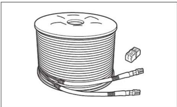
natural_image
Illustration of a coiled cable with two connectors and a small connector (no text or symbols)This is a 2-core single-mode optical fiber cable of 200 m (656 feet) long.
Using the supplied extension plug allows transmission of the video and control signal from a distance up to 2,000 m (6,562 feet).
Supplied accessories: extension plug (1)
Video Switcher (commercially available)
natural_image
Isometric line drawing of a rectangular electronic device with ports and indicator lights (no text or symbols)This switches the video signal input of multiple cameras.

System Configuration
The BRC-H900 HD Color Video Camera has various system configuration capabilities using optional products. This section describes seven typical system examples with the required components and the main usage of each system.
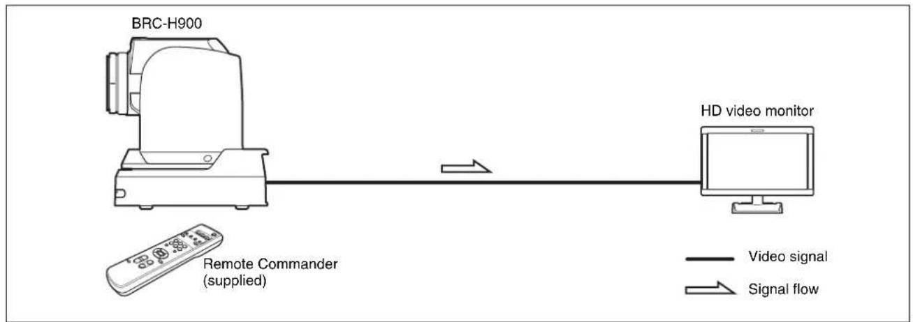
Operating a BRC-H900 Camera Using the Supplied Remote Commander
This system allows you:
To operate the camera readily from a short distance
System configuration
flowchart
graph LR
    A["BRC-H900"] -->|Remote Commander (supplied)| B["HD video monitor"]
    B -->|Signal flow| A
    style A fill:#f9f,stroke:#333
    style B fill:#ccf,stroke:#333
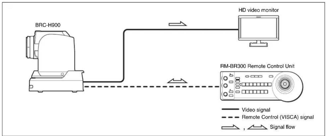
Operating a BRC-H900 Camera Using the RM-BR300 Remote Control Unit
This system allows you:
To perform pan/tilt and zoom operations using the joystick of the Remote Control Unit
System configuration
flowchart
graph LR
    A["BRC-H900"] -->|Video signal| B["HD video monitor"]
    B -->|Signal flow| C["RM-BR300 Remote Control Unit"]
    style A fill:#f9f,stroke:#333
    style B fill:#ccf,stroke:#333
    style C fill:#cfc,stroke:#333
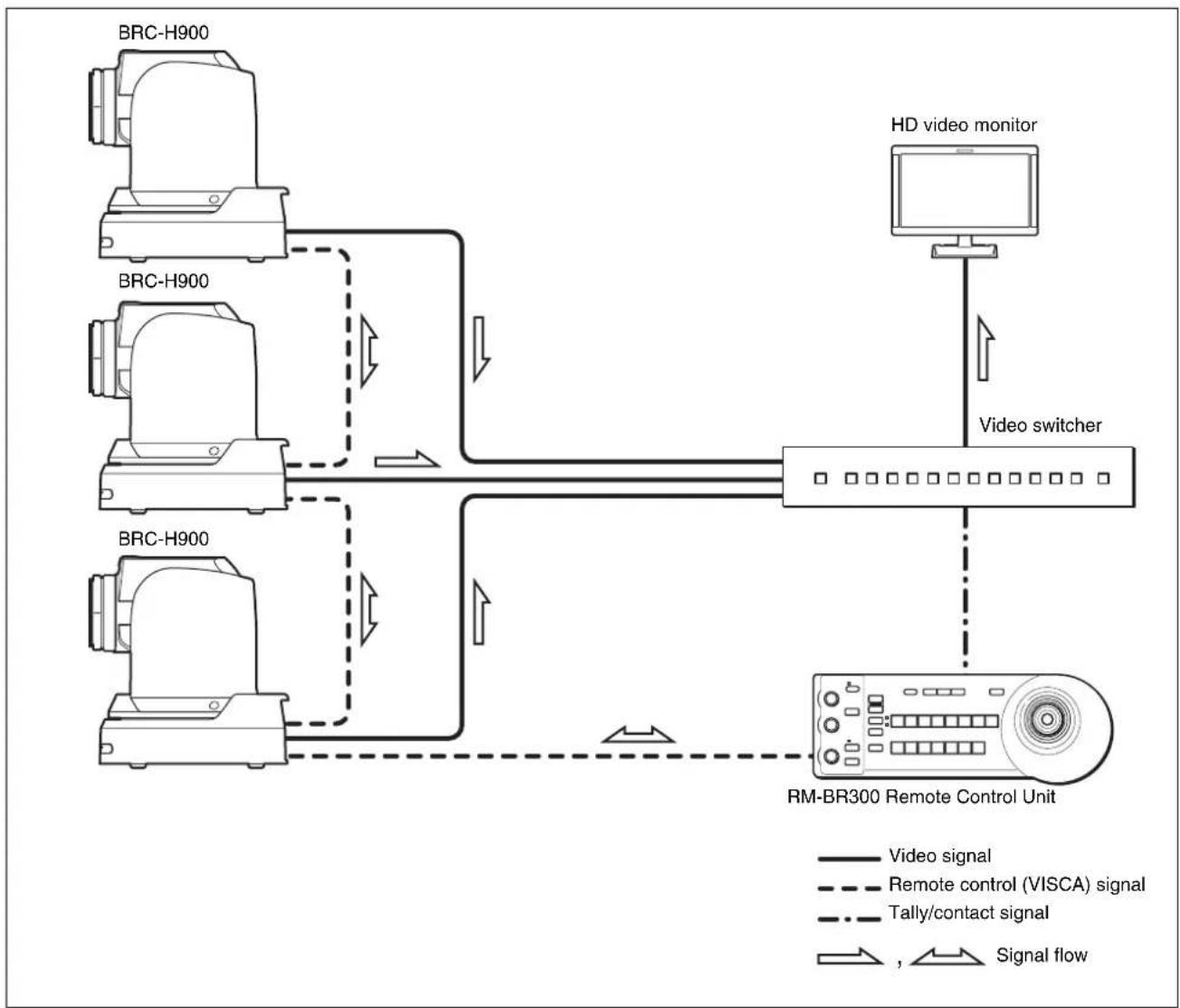
Operating Multiple BRC-H900 Cameras Using the RM-BR300 Remote Control Unit
This system allows you:
• To operate up to seven cameras remotely using a single Remote Control Unit
• To perform pan/tilt and zoom operations using the joystick
System configuration
flowchart
graph TD
    A["BRC-H900"] -->|Video signal| B["HD video monitor"]
    C["BRC-H900"] -->|Remote control (VISCA) signal| B
    D["BRC-H900"] -->|Tally/contact signal| B
    E["BRC-H900"] -->|Signal flow| F["RM-BR300 Remote Control Unit"]
    B --> G["Video switcher"]
    F --> G

Overview
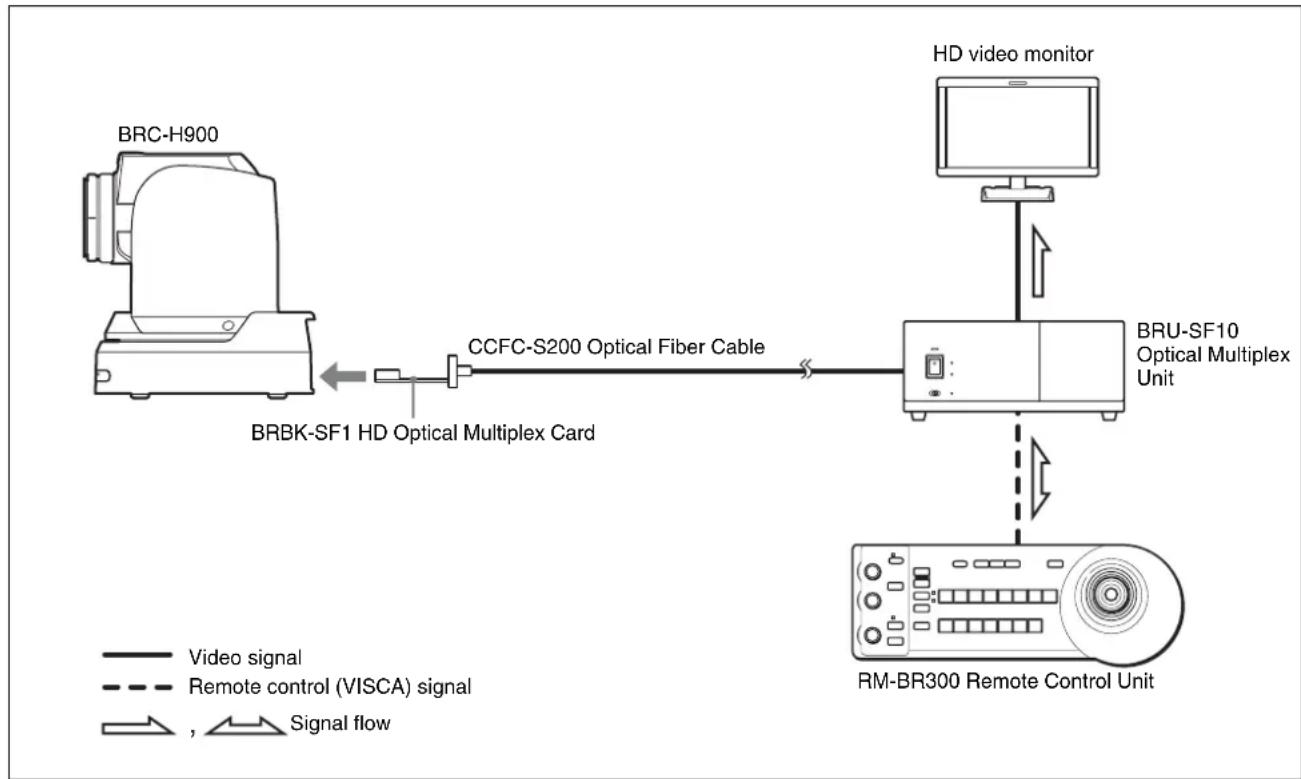
Operating a BRC-H900 Camera from a Long Distance
This system allows you:
• To operate the camera remotely from a distance up to 2,000 m (6,562 feet)
- To perform pan/tilt and zoom operations using the joystick
• To transmit the video and control signals of the camera to a distant place using the Optical Fiber Cable
System configuration
flowchart
graph TD
    A["BRC-H900"] -->|BRBK-SF1 HD Optical Multiplex Card| B["CCFC-S200 Optical Fiber Cable"]
    B --> C["HD video monitor"]
    C --> D["MR-BR300 Remote Control Unit"]
    D --> E["BRU-SF10 Optical Multiplex Unit"]
    style A fill:#f9f,stroke:#333
    style B fill:#ccf,stroke:#333
    style C fill:#cfc,stroke:#333
    style D fill:#fcc,stroke:#333
    style E fill:#ffc,stroke:#333
Notes
- Be sure to turn on the power of the BRC-H900 camera before you turn on the power of the BRU-SF10 HD Optical Multiplex Unit.
- The BRC-H900 camera does not operate if nothing is connected to the BRBK-SF1 HD Optical Multiplex Card inserted into the camera. To operate the camera, connect the BRU-SF10 Optical Multiplex Unit to the BRBK-SF1 using the CCFC-S200 Optical Fiber Cable and turn on the power of the BRU-SF10.
- When the BRBK-SF1 HD Optical Multiplex Card is inserted into the BRC-H900 camera, the EXT SYNC IN connector, VISCA RS-232C IN/OUT connectors, and VISCA RS-422 connector on the rear of the camera are disabled. Use the connectors and switches on the rear of the BRU-SF10 Optical Multiplex Unit instead.
- The optional CCFC-M100 and M100HG Optical Fiber Cable cannot be used with this system.
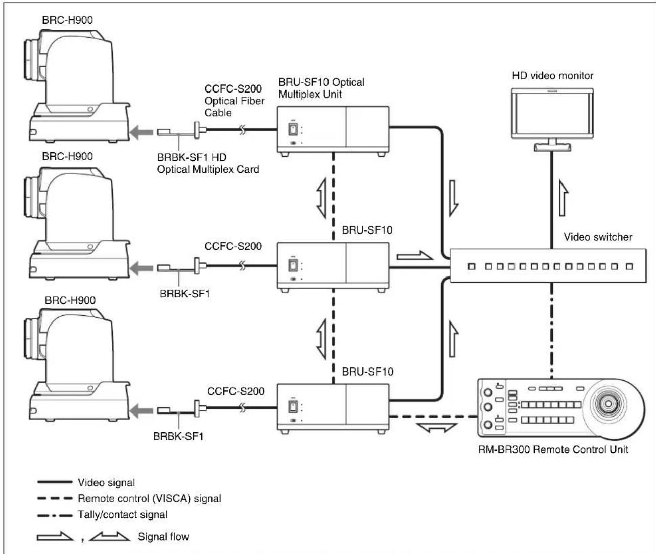
Operating Multiple BRC-H900 Cameras from a Long Distance
This system allows you:
• To operate up to seven cameras remotely from a distance up to 2,000 m (6,562 feet)
• To perform pan/tilt and zoom operations using the joystick
• To transmit the video and control signals of the cameras to a distant place using the Optical Fiber Cable
System configuration
flowchart
graph TD
    subgraph BRC_H900
        A["BRB-KSF1 HD Optical Multiplex Card"] --> B["CCFC-S200 Optical Fiber Cable"]
        C["BRB-KSF1"] --> D["CCFC-S200"]
        E["BRB-KSF1"] --> F["CCFC-S200"]
    end

    subgraph BRU-SF10 Optical Multiplex Unit
        G["BRU-SF10 Optical Multiplex Unit"] --> H["BRU-SF10"]
        I["BRU-SF10"] --> J["BRU-SF10"]
    end

    subgraph HD Video Monitor
        K["HD video monitor"] --> L["Video switcher"]
    end

    M["BRB-KSF1 HD Optical Multiplex Card"] --> N["BRB-KSF10 Optical Multiplex Unit"]
    O["BRB-KSF1"] --> P["BRB-KSF10 Optical Multiplex Unit"]
    Q["BRB-KSF1"] --> R["BRB-KSF10 Optical Multiplex Unit"]
    S["BRB-KSF1"] --> T["BRB-KSF10 Optical Multiplex Unit"]
    U["BRB-KSF1"] --> V["BRB-KSF10 Optical Multiplex Unit"]
    W["BRB-KSF1"] --> X["BRB-KSF10 Optical Multiplex Unit"]
    Y["BRB-KSF1"] --> Z["BRB-KSF10 Optical Multiplex Unit"]
    AA["BRB-KSF1"] --> AB["BRB-KSF10 Optical Multiplex Unit"]
    AC["BRB-KSF1"] --> AD["BRB-KSF10 Optical Multiplex Unit"]
    AE["BRB-KSF1"] --> AF["BRB-KSF10 Optical Multiplex Unit"]
    AG["BRB-KSF1"] --> AH["BRB-KSF10 Optical Multiplex Unit"]
    AI["BRB-KSF1"] --> AJ["BRB-KSF10 Optical Multiplex Unit"]
    AK["BRB-KSF1"] --> AL["BRB-KSF10 Optical Multiplex Unit"]
    AM["BRB-KSF1"] --> AN["BRB-KSF10 Optical Multiplex Unit"]
    AO["BRB-KSF1"] --> AP["BRB-KSF10 Optical Multiplex Unit"]
    AQ["BRB-KSF1"] --> AR["BRB-KSF10 Optical Multiplex Unit"]
    AS["BRB-KSF1"] --> AT["BRB-KSF10 Optical Multiplex Unit"]
    AU["BRB-KSF1"] --> AV["BRB-KSF10 Optical Multiplex Unit"]
    AW["BRB-KSF1"] --> AX["BRB-KSF10 Optical Multiplex Unit"]
    AY["BRB-KSF1 HD Optical Multiplex Card"] --> AZ["BRU-SF10 Optical Multiplex Unit"]
    BA["BRU-SF1"] --> BB["BRU-SF10 Optical Multiplex Unit"]
    BC["BRU-SF1"] --> BD["BRU-SF10 Optical Multiplex Unit"]
    BE["BRU-SF1"] --> BF["BRU-SF10 Optical Multiplex Unit"]
    BG["BRU-SF1"] --> BH["BRU-SF10 Optical Multiplex Unit"]
    BI["BRU-SF1"] --> BJ["BRU-SF10 Optical Multiplex Unit"]
    BK["BRU-SF1"] --> BL["BRU-SF10 Optical Multiplex Unit"]
    BM["BRU-SF1"] --> BN["BRU-SF10 Optical Multiplex Unit"]
    BO["BRU-SF1"] --> BP["BRU-SF10 Optical Multiplex Unit"]
    BQ["BRU-SF1"] --> BRU-SF10
    BS["BRU-SF1"] --> BT["BRU-SF10"]
    BU["SFOC"] --> BV["SFOC"]
    BW["SFOC"] --> BX["SFOC"]

Overview
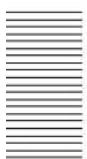
Operating Multiple BRC-H900 Cameras from Short and Long Distance
This system allows you:
• To operate up to seven cameras remotely by using a single RM-BR300 Remote Control Unit
• To perform pan/tilt and zoom operations using the joystick
- To operate remotely from a distance up to 2,000 m (6,562 feet) and to transmit the video and control signals of the cameras to a distant place using the Optical Fiber Cable
System configuration
flowchart
graph TD
    A["BRC-H900"] -->|Video signal| B["BRU-SF10 HD Optical Multiplex Unit"]
    C["BRC-H900"] -->|Remote control (VISCA) signal| B
    D["BRC-H900"] -->|Tally/contact signal| B
    E["BRC-H900"] -->|Signal flow| F["BRU-SF10 HD Optical Multiplex Unit"]
    G["BRBK-SF1"] --> H["CCFC-S200 Optical Fiber Cable"]
    I["BRBK-SF1 HD Optical Multiplex Card"] --> H
    J["HD video monitor"] --> K["Video switcher"]
    L["MR-BR300 Remote Control Unit"] --> K
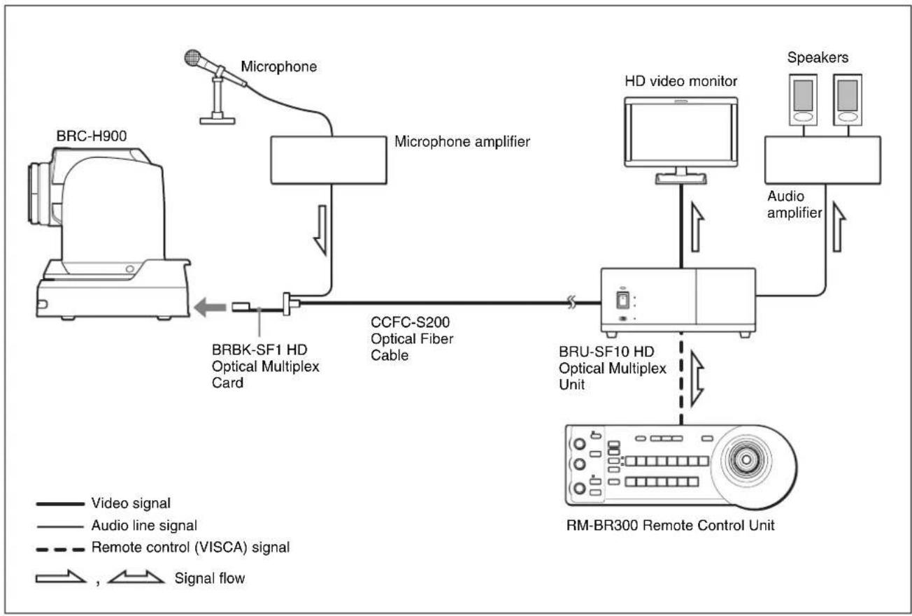
Transmitting Audio Signals Using the BRU-SF10
This system allows you:
• To operate the camera remotely from a distance up to 2,000m (6,562 feet)
• To perform pan/tilt and zoom operations using the joystick
• To transmit the video and control signals of the camera, and the audio signal input to the BRBK-SF1 Optical Multiplex Card, to a distant place using the Optical Fiber Cable
System configuration
flowchart
graph LR
    A["BRC-H900"] -->|BRBK-SF1 HD Optical Multiplex Card| B["Microphone"]
    B --> C["Microphone amplifier"]
    C --> D["CCFC-S200 Optical Fiber Cable"]
    D --> E["BRU-SF10 HD Optical Multiplex Unit"]
    E --> F["MR-BR300 Remote Control Unit"]
    F --> G["HD video monitor"]
    G --> H["Audio amplifier"]
    H --> I["Speakers"]
    style A fill:#f9f,stroke:#333
    style F fill:#ccf,stroke:#333
    style G fill:#cfc,stroke:#333
    style H fill:#fcc,stroke:#333
    style I fill:#ffc,stroke:#333

Overview
Location and Function of Parts
Camera
Front
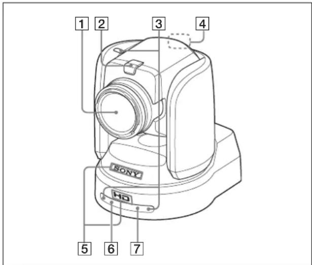
1 Lens
This is a 14-magnification optical zoom lens.
Note
Do not touch the part around the lens and ring outside the lens when energized. It may cause a malfunction of the camera.
2 Tally lamp
Lights in red when a VISCA tally command is received or the camera is selected by the RM-BR300 Remote Control Unit (not supplied) (depending on the setting mode).
You can set the brightness of the tally lamp to HIGH, LOW, or OFF on the menu.
3 Remote sensor
This is the sensor for the supplied Remote Commander.
When you use the upper remote sensor, set IMG FLIP to ON in the SYSTEM menu (page 40). With this setting the remote sensor at the rear of the camera does not function.
4 Back tally lamp
Lights in red when a VISCA tally command is received or the camera is selected by the RM-BR300 Remote Control Unit (not supplied) (depending on the setting mode). The back tally
lamp does not light when TALLY MODE in the SYSTEM menu (page 40) is set to OFF.
Flashes at intervals of about 0.7 seconds if the rotating speed of the cooling fan motor reduces or if the motor stops, regardless of the on/off status of the back tally lamp.
5SONY and HD nameplates
Pull them out to turn them over and attach upside down if required.
6 POWER lamp
Lights when the camera is connected to an AC outlet using the supplied AC power adaptor and AC power cord.
Flashes in green when the camera receives an operation command from the supplied Remote Commander.
7 STANDBY lamp
Lights when the camera is turned off using the Remote Commander.
Rear
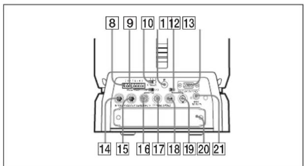
8 VISCA RS-422 connector
Used for VISCA control.
For connection to the VISCA RS-422 connector, see “Using the VISCA RS-422 Connector Plug” on page 90.
975-ohm termination switch
This switch is used when an external sync signal is used. Set it to OFF when this camera is in the middle of a daisy-chain connection of multiple cameras. Set it to ON when the camera is at the end of a daisy-chain connection or when nothing is connected to the EXT SYNC IN connector on the camera.
10 IR SELECT switch
Select the camera number when you operate multiple cameras with the same Remote Commander.
11 Remote sensor
This is the sensor for the supplied Remote Commander.
This remote sensor does not function when IMG FLIP is set to ON in the SYSTEM menu.
12 HD/SD select switch
Outputs an SD-SDI signal from the SDI connector when the switch is set to SD, or an HD-SDI signal from the SDI connector when the switch is set to HD.
Note
Set the switch before turning the camera on.
13 RGB/COMPONENT connector
Supplies the images as an analog component (YPbPr or RGB) signal.
14 VISCA RS-232C IN connector
Connect to the RM-BR300 Remote Control Unit (not supplied). When you connect multiple cameras, connect it to the VISCA RS-232C OUT connector of the previous camera in a daisy-chain connection.
15 VISCA RS-232C OUT connector
When you connect multiple cameras, connect it to the VISCA RS-232C IN connector of the next camera in a daisy-chain connection.
16EXT SYNC IN connector
Accepts external video sync signals.
17 ➕ VIDEO connector
Outputs the camera images as a composite video signal.
18 S-VIDEO connector
Outputs the camera images as an S video signal.
19 SDI connector
Outputs the video signal from the camera as an HD/SD-SDI signal.
Supplies down-converted SD-SDI signals that conform to the SMPTE 259M serial digital interface standards, or HD-SDI signals that conform to the SMPTE 292 serial digital interface standards. Select HD-SDI or SD-SDI signals with the HD/SD select switch.
20Card slot
Insert the optional card, such as BRBK-HSD2, BRBK-SA1, BRBK-SF1, etc.
The slot cover is attached to the camera at the factory.
21DC IN 12V connector
Connect the supplied AC power adaptor.
Bottom
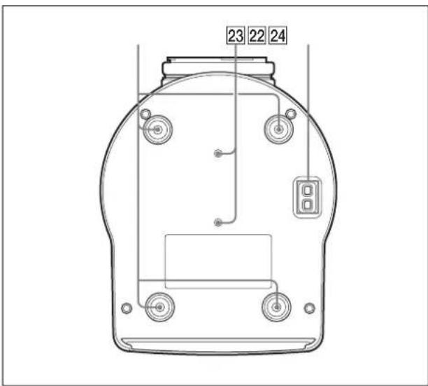
22Ceiling bracket mounting screw holes
When you install the camera to the ceiling or on a shelf, etc., in a high position, secure the supplied ceiling bracket to these holes using the supplied four screws. The four feet are attached to the holes at the factory.
For installation, see "Installing the Camera in a High Position" on page 57.
23Tripod screw holes (1/4-20UNC)
When you install the camera to a tripod, secure the tripod to these holes.
24 BOTTOM switches
Used for the output signal format selection, RS-232C/RS-422 selection, baud rate selection, remote control signal output on/off and camera address setting.
For details, see "Setting of the BOTTOM switches" on page 19.
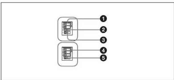
Setting of the BOTTOM switches
flowchart
graph TD
    A["Process Block 1"] --> B["Processing Unit 2"]
    C["Process Block 3"] --> D["Processing Unit 4"]
    E["Process Block 4"] --> F["Processing Unit 5"]
    style A fill:#f9f,stroke:#333
    style C fill:#f9f,stroke:#333
    style E fill:#f9f,stroke:#333
    style B fill:#ccf,stroke:#333
    style D fill:#ccf,stroke:#333
    style F fill:#ccf,stroke:#333

①Switch 1, 2 (signal format selector)
Depending on the setting of the Switch 1, 2, the signal format is changed as follows:
| Signal format | 1080/59.94i | 1080/50i 720/59.94p | 720/50p |
| Switch 1 OFF ON OFF ON | |||
| Switch 2 OFF OFF ON ON | |||
②Switch 3 (RS-232C/RS-422 selector)
Set to ON for RS-422, or OFF for RS-232C.
③Switch 4 (Communication baud rate selector)
Set to ON for 38,400 bps, or OFF for 9,600 bps.
④Switch 1, 2, 3 (Camera address selectors)
Set the address of the camera.
Normally set to "0". With this setting, addresses are assigned to the cameras automatically in the connected order by pressing the POWER button while holding down the RESET button on the RM-BR300 Remote Control Unit.
You can assign the camera address "1" to "7" manually by setting these selectors as follows:
| Camera address | 0 | 1 | 2 | 3 | 4 | 5 | 6 | 7 |
| Switch 1 | OFF | ON | OFF | ON | OFF | ON | ||
| Switch 2 | OFF | OFF | ON | ON | OFF | OFF | ON | ON |
| Switch 3 | OFF | OFF | OFF | OFF | ON | ON | ON | ON |
⑤Switch 4 (Infrared signal output switch)
Set to ON to enable an infrared signal output, or OFF to disable the output. For details about the output connector, see “Pin Assignments” on page 86.
Note
Set the switches before you turn on the power of the camera. The switch 4 (Infrared signal output switch) setting is effective whenever you change its setting.
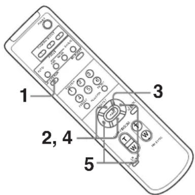
Remote Commander (supplied)
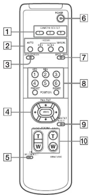
1 CAMERA SELECT buttons
Press the button corresponding to the camera you want to operate with the Remote Commander.
The camera number can be set using the IR SELECT switch on the rear of the camera.
Note
If two or more cameras are adjacent and have the same camera number, they are operated simultaneously with the same Remote Commander.
When you install the cameras close to each other, set different camera numbers.
For the camera number setting, see “Operating Multiple Cameras with the Remote Commander” on page 46.
2FOCUS buttons
Used for focus adjustment.
Press the AUTO button to adjust the focus automatically. To adjust the focus manually, press the MANUAL button, and adjust it with the FAR and NEAR buttons.
3 DATA SCREEN button
Press this button to display PAGE of the main menu. Press it again to turn off the menu. If you press the button when a lower-level menu is selected, the display goes back to a higher-level menu.
Note
Pan/tilt and zoom operations are disabled when the menu is displayed.
4 PAN-TILT buttons
Press the arrow buttons to perform panning and tilting. Press the HOME button to face the camera back to the front.
When the menu is displayed, use or to select the menu items and or to change the set values.
5 L/R DIRECTION SET button
Hold down this button and press the REV button to change the direction of the camera movement opposite to that indicated by the arrow of the ◀/► buttons.
To reset the direction of the camera movement, press the STD button while holding down this button.
6 POWER button
Press this button to turn on/off the camera when the camera is connected to an AC outlet.
7 BACK LIGHT button
Press this button to enable the backlight compensation. Press it again to disable the backlight compensation.
Note
This function is effect when MODE in the EXPOSURE menu is set to FULL AUTO or BACK LIGHT.
8 POSITION buttons
Hold down the PRESET button and press button 1 to 6 to store the current camera direction, zoom, focus adjustment and backlight compensation in the memory of the pressed number button. To erase the memory contents, hold down the RESET button and press button 1 to 6.
Note
Some memory contents may not be erased even if you use the RESET button.
For details of items that can be stored by the PRESET button and erased by the RESET button, see “Presetting Items” on page 79.
9 PAN-TILT RESET button
Press this button to reset the pan/tilt position.
10 ZOOM buttons
Use the SLOW button to zoom slowly, and the FAST button to zoom quickly.
Press the T (telephoto) side of the button to zoom in, and the W (wide angle) side to zoom out.
To install batteries
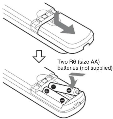
Installing batteries
Two R6 (size AA) batteries are necessary for Remote Commander (RM-EV100).
To avoid risk of explosion, use R6 (size AA) manganese or alkaline batteries.
CAUTION
Danger of explosion if battery is incorrectly replaced. Replace only with the same or equivalent type recommended by the manufacturer.
When you dispose of the battery, you must obey the law in the relative area or country.
ATTENTION
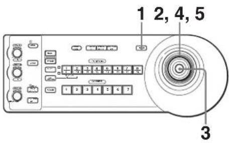
RM-BR300 Remote Control Unit (not supplied)
This manual explains the operations of the RM-BR300 Remote Control Unit when it is used with BRC-H900 cameras.
Front
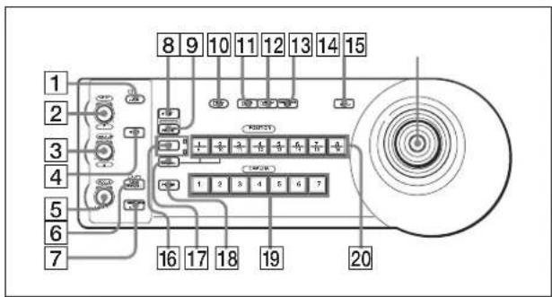
1 LOCK button and indicator
Press the LOCK button for more than one second, the LOCK indicator lights and the values set by the VALUE/R, BRIGHT/B and FOCUS controls are locked. (The indicators of the locked controls are turned off.) The AUTO/MANUAL button is also disabled.
Press the LOCK button for more than one second again to unlock the controls and buttons.
2 VALUE/R control
When the brightness adjustment mode is selected with the MODE button (with the VALUE indicator lit):
Adjusts the value of the item (SHUTTER, IRIS or GAIN) selected through the menu of the camera. When the VALUE indicator is lit, the function of the control varies according to the MODE setting in the EXPOSURE menu of the camera. For details, see “Functions of the VALUE and BRIGHT controls” on page 54.
When the white balance adjustment mode is selected with the MODE button (with the R indicator lit):
The function of the control with the R indicator lit varies according to the white balance mode selected on the camera. For details, see “Functions of the R and B controls” on page 53.
③ BRIGHT/B control
When the brightness adjustment mode is selected with the MODE button (with the BRIGHT indicator lit):
Adjusts the brightness settings of the camera, etc. When the BRIGHT indicator is lit, the function of the control varies according to the MODE setting in
the EXPOSURE menu of the camera. For details, see "Functions of the VALUE and BRIGHT controls" on page 54.
When the white balance adjustment mode is selected with the MODE button (with the B indicator lit):
The function of the control with the B indicator lit varies according to the white balance mode selected on the camera. For details, see “Functions of the R and B controls” on page 53.
4 MODE button
Press this button to select the function of the VALUE/R control and BRIGHT/B control. When the brightness adjustment mode is selected, the VALUE and BRIGHT indicators are lit. When the white balance adjustment mode is selected, the R and B indicators are lit.
5FOCUS control
Turn this control counterclockwise (toward NEAR) to focus on a near subject, and clockwise (toward FAR) to focus on a far subject.
6 AUTO/MANUAL button and AUTO indicator
Press this button to select focus mode, AUTO or MANUAL. When AUTO is selected, the AUTO indicator lights and the FOCUS control and the ONE PUSH AF button are disabled. When MANUAL is selected, the FOCUS control and the ONE PUSH AF button are enabled (with the FOCUS indicator lit).
7 ONE PUSH AF button
Press this button to perform the one-push auto focus function.
8 RESET button
Hold down this button and press one of the POSITION buttons, and the memory of the camera corresponding to the pressed POSITION button is cleared to the factory-preset conditions. When multiple cameras are connected, hold down this button and press the POWER button to set the camera addresses automatically.
Note
Some memory contents may not be erased even if you use the RESET button.
For details about item erased by the RESET button, see "Presetting Items" on page 79.
9PRESET button
Hold down this button and press one of the POSITION buttons, and the current camera settings are stored in the memory of the camera corresponding to the pressed POSITION button.
10 PANEL LIGHT button
Press this button to illuminate all the POSITION buttons and CAMERA buttons. Press the button again to turn off the illumination.
When FULL AUTO, or BACK LIGHT is selected with MODE of the EXPOSURE menu, press this button to set the backlight compensation function of the camera to on/off. Each time you press this button, the backlight compensation function toggles between on and off.
When FULL AUTO or SPOT LIGHT is selected with MODE of the EXPOSURE menu, hold down the SHIFT button and press this button to set the spotlight compensation function of the camera to on/off. Each time you press this button, the spotlight compensation function toggles between on and off.
12PAN-TILT RESET button
Press this button to reset the pan/tilt position of the camera to the initial conditions.
13 ONE PUSH AWB button
When ONE PUSH is selected with the WHITE BALANCE menu of the camera, press this button to perform the one-push white balance adjustment.
14 MENU button
Press this button for about one second to display or turn off the menu of the camera, or return to the main menu.
15Joystick
When the menu of the camera is not displayed
The joystick is used for pan/tilt and zoom operations.
When you incline the joystick right and left, the camera pans. When you incline it forward or backward, the camera tilts. The pan/tilt speed changes according to the angle of the inclination. When you release the joystick, the camera movement stops.
When you turn the dial on the upper part of the joystick clockwise, the subject becomes larger (zoom in). When you turn it counterclockwise, the subject becomes smaller (zoom out).
When you press the button on the top of the joystick for one or two seconds regardless of the PAN TILT
ZOOM menu setting, the pan/tilt/zoom are reset and the camera returns to the front.
When the menu of the camera is displayed
The joystick is used for menu operations. Inclining the joystick right, left, forward and backward has the same function as pressing the arrow buttons of the supplied Remote Commander. Pressing the button on the top of the joystick has the same function as pressing the HOME button on the Remote Commander.
16SHIFT button and indicators
Hold down this button and press one of the POSITION buttons. The lower indicator lights and you can use the POSITION buttons for positions 9 to 16. If you release the SHIFT button, the upper indicator lights and the POSITION buttons can be used for positions 1 to 8.
17 L/R DIRECTION button
Hold down this button and press POSITION button 2 (REV) to reverse the pan direction to the direction in which you incline the joystick. To reset the direction, hold down this button and press POSITION button 1 (STD).
18 POWER button
Press this button to light the CAMERA button(s) corresponding to the status of the connected camera(s).
Blue: The power of the camera is on.
Yellow green: The camera is in standby mode.
Off: No camera is connected.
Hold down this button and press CAMERA button 1 to 7 to turn on/off the power of the camera corresponding to the pressed button.
19 CAMERA buttons
Press one of the buttons to select the camera from among those connected. The selected CAMERA button lights in blue.
20 POSITION buttons
You can store the various camera settings such as the pan, tilt and zoom positions to the memory of the camera corresponding to each POSITION button, and load the settings in the memory.

Rear/Bottom
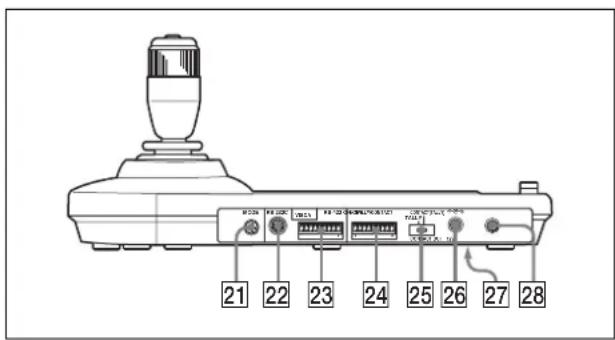
21MODE selector
Select the position corresponding to the VISCA-controllable camera to be connected.
| Switch position Camera mode | ||
| 0 Automatically selected (default) | ||
| 1 BRC-300/300P | ||
| 2 EVI-D70/D70P | ||
| 3 EVI-D100/D100P | ||
| 4 EVI-D30/D30P | ||
| 5 | S | N |
| 6 BRC-H700 | ||
| 7 BRC-Z700 | ||
| 8 BRC-Z330 | ||
| 9 BRC-H900 | ||
Note
Set the selector to position 9 when all the connected cameras are BRC-H900s. For other connections, set the selector to position 0.
22 VISCA RS-232C connector
Connect to the VISCA RS-232C IN connector of the camera or the BRU-SF10 HD Optical Multiplex Unit.
23 VISCA RS-422 connector
Connect to the VISCA RS-422 connector of the camera or the BRU-SF10 HD Optical Multiplex Unit.
An RS-422 connector plug is attached at the factory.
24 TALLY/CONTACT connector
This connector is used for the tally lamp input or the contact output.
Select the function of the connector using the TALLY/CONTACT selector.
An RS-422 connector plug is attached at the factory.
25 TALLY/CONTACT selector
Select the function of the TALLY/CONTACT connector.
TALLY: The tally lamp of the camera selected with the connected switcher lights.
CONTACT: The contact output corresponding to the camera address selected with the Remote Control Unit is short-circuited against the connected switcher.
CONTACT (TALLY): The contact output corresponding to the camera address selected with the Remote Control Unit is short-circuited against the connected switcher and the tally lamp of the camera selected with the connected switcher lights.
Notes
- Change the setting of the selector before you turn on the power of the Remote Control Unit. Otherwise, the setting is not effective.
- For details about the TALLY/CONTACT selector, refer to the Operating Instructions of RM-BR300.
26 DC IN 12V connector
C Connect the supplied AC power adaptor.
Z
27 DIP switches (bottom)
Switch 1 (RS-232C/RS-422 selector)
Set to ON for RS-422, or OFF for RS-232C.
Switch 2 (Communication baud rate selector)
Set to ON for 38,400 bps, or OFF for 9,600 bps.
Switch 3 (BRIGHT control function selector)
Set to ON for IRIS and GAIN adjustments, or OFF for IRIS adjustment only.
Note
Set the DIP switches before you turn on the power of the Remote Control Unit. Otherwise, the setting is not effective.
28 ON/OFF switch
Press this switch to turn on/off the Remote Control Unit.
BRU-SF10 HD Optical Multiplex Unit (not supplied)
Front
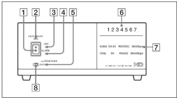
1 Power switch
Turns on/off the power of this unit. Turn on the power of the BRC-H900 camera before you turn on this unit.
2 Power indicator
Off: The unit's power switch is turned off.
Lit orange: The unit is starting up or in sleep mode.
Lit green: The unit is in normal operation.
3LINK indicator
Lit green: The optical fiber connection between the unit and the camera is normal. (The indicator lights in green after the system starts up.)
Lit red: Check for the following.
- The BRU-SF10 is not properly connected to the camera via optical fiber cable. Check the connections, and restart the unit.
- Image frequency settings for the camera and the BRU-SF10 are different. Check the settings after turning off the power, then restart the unit.
- The camera may be unable to start properly due to the AC adaptor being improperly connected to the DC IN connector on the camera. Check that the camera is turned on.
4 ALARM indicator
Lit red: Check for the following.
- The BRU-SF10 is not properly connected to the camera via an optical fiber cable. Check the connections, then restart the unit.
- Image frequency settings for the camera and the BRU-SF10 are different. Check the settings after turning off the power, then restart the unit.
- The camera may be unable to start properly due to the AC adaptor being improperly connected to the DC IN connector on the camera. Check that the camera is turned on.
- An unsupported optional interface card is inserted in the card slot of the BRU-SF10. Remove the card after turning off the power, then restart the unit.
Off: The unit is in normal operation.
5 SD indicator
This indicator lights when a BRBK-SA1 optional interface card is installed, or when a BRBK-HSD2 is installed and its rear switch is set to SD.
6 Camera ID indicators
The number for the current camera address lights in orange. For details on setting the camera address, see “17 VISCA FUNCTION switches” on page 26.
7 Status indicators
The current communication format, baud rate, and video format settings light in green. For details on configuring these settings, see “17 VISCA FUNCTION switches” on page 26.
8 DATA MIX switch
When the SD indicator is lit, set this switch to ON to overlap the menu display with the SD image signals from any installed BRBK-SA1 and BRBK-HSD2 interface card on which the rear switch is set to SD. Set this switch to OFF to hide the menu display.
Rear
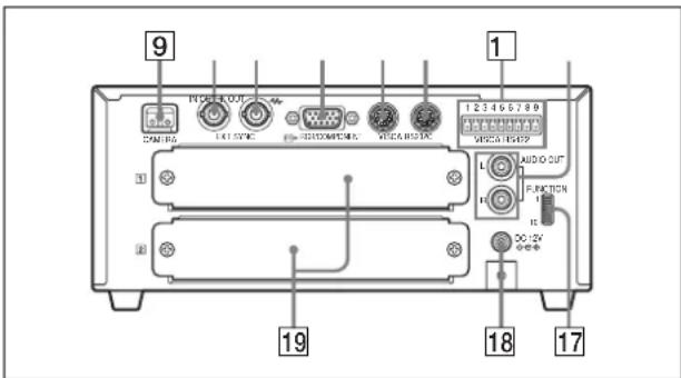
9 CAMERA connector
Connect to the optical connector of the BRBK-SF1 HD Optical Multiplex Card installed in the BRC-H900 camera using the CCFC-S200 Optical Fiber Cable. A dustproof cap is attached at the factory. Do not remove this cap if you do not intend to connect an optical fiber cable. Dustproof caps are also attached to the BRBK-SF1 and CCFC-S200. Do not remove these caps when the connectors are not in use.
10EXT SYNC IN connector
Accepts external video sync signals.

11EXT SYNC OUT connector
Supplies external video sync signals input from the EXT SYNC IN connector.
When a cable is connected to this connector, the 75-ohm termination for inputs is automatically opened, and signals input to the EXT SYNC IN connector are output from this connector.
12 RGB/COMPONENT connector
Supplies the images from the camera as a YPbPr or RGB signal.
13 VISCA RS-232C IN connector
Connect to the RM-BR300 Remote Control Unit (not supplied). When you connect multiple cameras, connect it to the VISCA RS-232C OUT connector of the previous camera in a daisy-chain connection.
14 VISCA RS-232C OUT connector
When you connect multiple cameras, connect it to the VISCA RS-232C IN connector of the next camera in a daisy-chain connection.
Caution
When you connect the RS-232C connecting cable of the unit to a peripheral device, use the supplied cable to prevent malfunction due to radiation noise.
15 VISCA RS-422 connector
Connect to the VISCA RS-422 connector of the camera or another BRC-H900 HD Optical Multiplex Unit.
For the connection to the VISCA RS-422
connector, see "Using the VISCA RS-422
Connector Plug" on page 90.
16 AUDIO OUT L/R jacks
Loop through output of the audio line signal input from the AUDIO IN jacks on the BRBK-SF1 HD Optical Multiplex Card inserted into the camera via the Optical Fiber Cable.
17 VISCA FUNCTION switches
These switches are used for the VISCA communication settings.
Switch 1 (RS-232C/RS-422 selector)
Set to ON for RS-422, or OFF for RS-232C.
Switch 2 (Communication baud rate selector)
Set to ON for 38,400 bps, or OFF for 9,600 bps.
Switches 3 to 5 (Camera address selectors)
Set the address of the camera.
Normally set to "0". With this setting, addresses are assigned to the cameras automatically in the connected order by pressing the POWER button while holding down the RESET button on the RM-BR300 Remote Control Unit (not supplied).
You can assign the camera address "1" to "7" manually by setting these selectors as follows:
| Camera address | 0 | 1 | 2 | 3 | 4 | 5 | 6 | 7 |
| Switch 3 | OFF | ON | OFF | ON | OFF | ON | OFF | ON |
| Switch 4 | OFF | OFF | ON | ON | OFF | OFF | ON | ON |
| Switch 5 | OFF | OFF | OFF | OFF | ON | ON | ON | ON |
Note
Cameras with addresses assigned by setting the switches to “0” and cameras with addresses assigned to “1” to “7” cannot be used together. In addition, the same address cannot be assigned to multiple cameras.
Switch 6 (59.94/50 signal format selector)
Set to ON for output of 50 signal format, or OFF for output of 59.94 signal format.
The 1080i and 720p formats are automatically applied to this unit based on the BOTTOM switch setting of the camera.
Be sure to configure the same setting on this unit and the camera.
Switches 7 to 10: Not used. Set them to OFF.
Note
Set the switches before you turn on the power of the unit.
18DC 12 V connector
Connect to the supplied AC adaptor.
19 Card slot
Install BRBK-SA1 or BRBK-HSD2 optional interface card here.
The slot cover is attached to the unit at the factory.
BRBK-SF1 HD Optical Multiplex Card (not supplied)
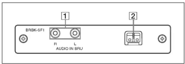
1 AUDIO IN L/R jacks (phono type)
Input an audio signal (stereo), which is output from the AUDIO OUT jacks on the BRU-SF10 HD Optical Multiplex Unit via the Optical Fiber Cable.
Note
The audio input on this card accepts audio line signals only. When you input audio signals from a microphone, etc., it should be connected with a microphone amplifier so that audio signals with an appropriate audio level can be input.
2 Optical connector
Performs the optical digital multiplex transmission of video, audio, external sync and control signals. A dustproof cap is attached at the factory.
BRBK-HSD2 HD/SD-SDI Output Card (not supplied)
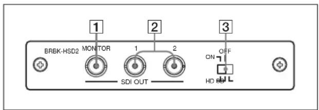
① SDI MONITOR OUT connector (BNC type)
Outputs down-converted SD-SDI signals that conform to SMPTE 259M serial digital interface standards, and down-converted HD-SDI signals that conform to SMPTE 292 serial digital interface standards. When the menu display for the camera is turned ON, the menu display signal that overlaps the images is output from this connector. When the SD-SDI output card is installed in the card slot of the BRU-SF10 HD Optical Multiplex Unit, you can also hide the menu display by using the DATA MIX switch on the BRU-SF10. For details, see “Images when menu display is ON” on page 27.
2 SDI connectors 1, 2 (BNC type)
Outputs down-converted SD-SDI signals that conform to SMPTE 259M serial digital interface standards, and down-converted HD-SDI signals that conform to SMPTE 292 serial digital interface standards.
When the menu display for the camera is turned ON, you can select whether to overlap the menu display with the image by using the 3 panel switch. For details, see “Images when menu display is ON” on page 27.
3 Panel switch
Switch between SD-SDI signals and HD-SDI signals.
When outputting HD-SDI signals, you can select whether to overlap the menu display with the image output from SDI connectors 1 and 2. For details, see “Images when menu display is ON” on page 27.
Notes
- SD-SDI and HD-SDI signals cannot be supplied simultaneously.
- Set the panel switch before turning on the camera.
- Do not push the switch forcibly with a screwdriver, etc.
Images when menu display is ON
When a BRBK-HSD2 is installed in the BRC-H900 card slot
| BRBK-HSD2 panel switch | MONITOR connector | SDI connectors 1, 2 |
| Left position HD/ DATA MIX: ON (HD-SDI output) | ○ | |
| Middle position HD/ DATA MIX: OFF (HD-SDI output) | ○× | |
| Right position SD (SD-SDI output) | ○ | |
○: Menu is superimposed on image
×: Menu is not superimposed on image

When a BRBK-HSD2 is installed in the BRU-SF10 card slot
| BRBK-HSD2 panel switch | MONITOR connector | SDI connectors 1, 2 |
| Left position HD/ DATA MIX: ON (HD-SDI output) | ○ | |
| Middle position HD/ DATA MIX: OFF (HD-SDI output) | ○× | |
| Right position SD (SD-SDI output) | ○/x^1) | |
○: Menu is superimposed on image
×: Menu is not superimposed on image
^1) When the DATA MIX switch on the front panel of the BRU-SF10 HD Optical Multiplex Unit is set to ON, the menu display is overlapped on all images output from the card. When the DATA MIX switch is set to OFF, the menu is not displayed.
BRBK-SA1 Analog SD Output Card (not supplied)
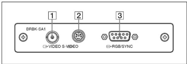
1→VIDEO connector (BNC type)
Supplies analog composite signals. The aspect ratio can be configured in the SD menu of the camera.
2 S-VIDEO connector (4-pin mini-DIN)
Outputs S-Video signals. You can configure the aspect ratio with the SD menu of the camera.
3 RGB/SYNC connector (D-sub 9-pin)
Supplies various analog signals such as composite video, S video, component video and RGB signals. The output signal can be selected in the SD menu of the camera.
Notes
- When a BRBK-SA1 Analog SD Output Card is installed in the BRC-H900 HD Color Video Camera and menu display for the camera is turned ON, the menu display is overlapped with the image.
- When a BRBK-SA1 Analog SD Output Card is installed in a BRU-SF10 HD Optical Multiplex Unit on which the front panel DATA MIX switch is set to ON and menu display for the camera is turned ON, the menu display is overlapped with the image. When the
DATA MIX switch is set to OFF, the menu will not be displayed on the image, even if menu display for the camera is turned ON.
Adjusting and Setting With Menus
About On-Screen Menus
You can change various settings, such as shooting conditions and system setup of the camera, while observing menus displayed on a connected monitor. This section explains how to read the on-screen menus before starting menu operations.
For full details of menu configurations, see page 76.
Note
You cannot perform pan/tilt and zoom operations while the menu is displayed.
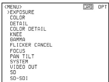
Main Menu
To display the main menu, press the DATA SCREEN button on the supplied Remote Commander or the MENU button on the RM-BR300 Remote Control Unit.
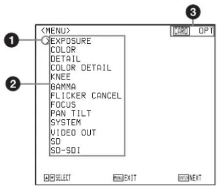
① Cursor
Selects a setting menu.
Move the cursor up or down by pressing the ↑ or ↓ button on the Remote Commander or by inclining the joystick of the RM-BR300 Remote Control Unit forward or backward.
②Menu items
To display a setting menu, select it using the ↑ or ↓ button on the Remote Commander or the joystick of the RM-BR300 Remote Control Unit, and press the HOME button on the Remote Commander or the top button of the joystick on the RM-BR300.
③Option card indicator
Displays the name of the interface card inserted into the card slot of the camera.
Setting Menus
The setting menu selected on the main menu is displayed.
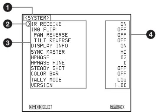
①Setting menu
The name of the menu currently selected is displayed here.
② Cursor
Selects a setting item.
Move the cursor up or down by pressing the ↑ or ↓ button on the Remote Commander or inclining the joystick of the RM-BR300 Remote Control Unit forward or backward.
③Setting items
The setting items for this setting menu are displayed.
To change a value, select the item using the or button on the Remote Commander or the joystick of the RM-BR300 Remote Control Unit, and press the or button on the Remote Commander or incline the joystick on the RM-BR300 right or left.
④ Set value
The currently set values are displayed.
To change a set value, use the ◀ or ➤ button on the Remote Commander or the joystick of the RM-BR300 Remote Control Unit.
For the default value of each setting item, see "Menu Configuration" on page 76.
Operation Through Menus
This section explains how to operate the menu using the supplied Remote Commander, or using the RM-BR300 Remote Control Unit (not supplied).
For details on each menu, see pages 32 through 44.
Menu Operation Using the Supplied Remote Commander
1 Press the DATA SCREEN button. The main menu appears.
2 Move the cursor to the menu item to be set by pressing the ↑ or ↓ button.
3 Press the HOME button. The selected menu appears.
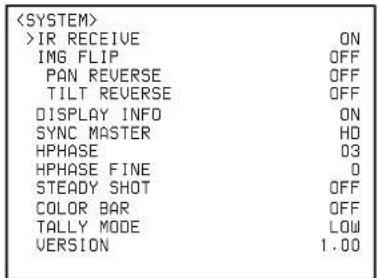
| >IR RECEIVE | ON |
| IMG FLIP | OFF |
| PAN REVERSE | OFF |
| TILT REVERSE | OFF |
| DISPLAY INFO | ON |
| SYNC MASTER | HD |
| HPHASE | 03 |
| HPHASE FINE | 0 |
| STEADY SHOT | OFF |
| COLOR BAR | OFF |
| TALLY MODE | LOW |
| VERSION | 1.00 |
4 Move the cursor to the setting item to be changed by pressing the ↑ or ↓ button.
5 Change the value by pressing the or button.
| >IR RECEIVE | ON |
| IMG FLIP | OFF |
| PAN REVERSE | OFF |
| TILT REVERSE | OFF |
| DISPLAY INFO | ON |
| SYNC MASTER | HD |
| HPHASE | 03 |
| HPHASE FINE | 0 |
| STEADY SHOT | OFF |
| COLOR BAR | OFF |
| TALLY MODE | LOW |
| VERSION | 1.00 |
Note
When you are operating the menu using the supplied Remote Commander, you cannot set IR RECEIVE in the SYSTEM menu to OFF. To set IR RECEIVE to OFF, use the RM-BR300 Remote Control Unit or the VISCA command.
To return to the main menu
Press the DATA SCREEN button.
To return to the normal display
When the main menu is displayed, press the DATA SCREEN button. When a sub-menu is displayed, press it twice.
Menu Operation Using the RM-BR300 Remote Control Unit
1 Press the MENU button for about one second. The main menu appears.
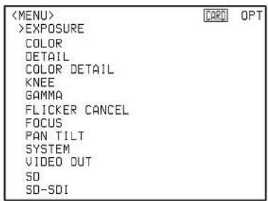
2 Move the cursor to the menu item to be set by inclining the joystick forward or backward.
3 Press the button on the top of the joystick. The selected menu appears.
4 Move the cursor to the setting item to be changed by inclining the joystick forward or backward.
5 Change the value by inclining the joystick right or left.
To return to the main menu
Press the MENU button to return to the main menu.
To return to the normal display
When the main menu is displayed, press the MENU button. When a sub-menu is displayed, press it twice.
EXPOSURE Menu
The EXPOSURE menu is used to set the items regarding the exposure.
| <EXPOSURE> | |
| >MODE | FULL AUTO |
| AE SPEED | MID |
| AE LEVEL | 0 |
| AGC | ON |
| AGC LIMIT | 12dB |
| AGC POINT | F2.8 |
| AUTO SHUTTER | ON |
| SHUTTER LIMIT | 1/250 |
| SHUTTER POINT | F16 |
MODE (exposure mode)
FULL AUTO: The exposure is adjusted automatically using the sensitivity, electronic shutter speed and iris.
MANUAL: The sensitivity (GAIN), electronic shutter speed (SPEED) and iris (IRIS) are adjusted manually.
SHUTTER Pri: Shutter Priority mode. The exposure is adjusted automatically using the sensitivity and iris. Adjust the electronic shutter speed (SPEED) manually.
IRIS Pri: Iris Priority mode. The exposure is adjusted automatically using the sensitivity and electronic shutter speed. Adjust the iris (IRIS) manually.
BACK LIGHT: Back light function.
SPOT LIGHT: This function allows exposure adjustment at darker levels if a portion of the object to be shot is illuminated.
Note
You cannot use both of the BACK LIGHT and SPOT LIGHT functions at the same time.
When you select MODE, some of the following setting items that are required for the selected mode appear.
GAIN: Select the gain.
You can select the gain to -3 or to within the range 0 to 24 dB in units of 1 dB when MODE is set to MANUAL.
SPEED: When MODE is set to MANUAL or SHUTTER Pri, select the electric shutter speed from among the following:
For the 1080/59.94i or 720/59.94p signal format
1/60, 1/100, 1/120, 1/125, 1/250, 1/500, 1/1000, 1/2000, 1/4000, 1/8000
For the 1080/50i or 720/50p signal format
1/50, 1/100, 1/120, 1/125, 1/250, 1/500,
1/1000, 1/2000, 1/4000, 1/8000, EX1 (1/60)
IRIS: When MODE is set to MANUAL or IRIS Pri, select the iris from among the following: F1.9/F2.2/F2.4/F2.6/F2.8/F3.1/F3.4/F3.7/F4.0/ F4.4/F4.8/F5.2/F5.6/F6.2/F6.8/F7.3/F8.0/F8.7/ F9.6/F10/F11/F12/F13/F15/F16/CLOSE (CLOSE is selectable only when MODE is set to MANUAL.)
AE SPEED: Select the exposure adjustment speed at which an optimum exposure value is obtained automatically. You can select LOW (slow speed), MID (normal speed) or HIGH (fast speed). Select when the brightness of the object is changed momentarily.
This function is available when MODE is set to FULL AUTO, SHUTTER Pri, IRIS Pri, BACK LIGHT, or SPOT LIGHT. If MODE is set to IRIS Pri, this function is not available when AGC and AUTO SHUTTER is set to OFF.
AE LEVEL: Select the level of the automatic exposure adjustment. Select the iris from among -1.0, -0.5, 0, +0.5, and +1.0.
This function is available when MODE is set to FULL AUTO, SHUTTER Pri, IRIS Pri, BACK LIGHT, or SPOT LIGHT. If MODE is set to IRIS Pri, this function is not available when AGC and AUTO SHUTTER are set to OFF.
AGC (auto gain control)
Set the automatic gain control function for a dark subject. When AGC is set to OFF, GAIN is set to 0 even if the subject becomes dark.
This function is available when MODE is set to FULL AUTO, SHUTTER Pri, IRIS Pri, BACK LIGHT, or SPOT LIGHT.
AGC LIMIT (auto gain limit setting): Set the maximum gain level while AGC is set to ON. Select a value from among 3, 6, 9, 12, and 18 dB. This function is available when MODE is set to FULL AUTO, SHUTTER Pri, IRIS Pri, BACK LIGHT, or SPOT LIGHT and AGC is set to ON.
AGC POINT (switching point for auto gain): Select the iris value that the auto gain control function is activated from among F5.6, F4, and F2.8. This function is available when MODE is set to FULL AUTO, SHUTTER Pri, BACK LIGHT, or SPOT LIGHT and AGC is set to ON. After activating the auto gain control function, the iris starts to be adjusted from the value that is set in AGC POINT when the gain level reaches to the maximum value that is set in AGC LIMIT.
AUTO SHUTTER
When the subject becomes bright, set the automatic shutter speed function. When AUTO SHUTTER is set to OFF, the shutter speed is set to 1/60 (for 1080/59.94i or 720/59.94p) or 1/50 (for 1080/50i or 720/50p) even if the subject becomes bright.
This function is available when MODE is set to FULL AUTO, IRIS Pri, BACK LIGHT, or SPOT LIGHT.
SHUTTER LIMIT (auto shutter limit setting): Select the maximum shutter speed while AUTO SHUTTER is set to ON. Select a value from among 1/100, 1/125, 1/250, and 1/500.
This function is available when MODE is set to FULL AUTO, IRIS Pri, BACK LIGHT, or SPOT LIGHT and AUTO SHUTTER is set to ON.
SHUTTER POINT (switching point for auto shutter limit): Select the iris value that the auto shutter speed function is activated from among F5.6, F8.0, F11, and F16.
This function is available when MODE is set to FULL AUTO, BACK LIGHT, or SPOT LIGHT and AUTO SHUTTER is set to ON. After activating the automatic shutter speed function, the iris starts to be adjusted from the value that is set in AGC POINT when the gain level reaches to the maximum value that is set in SHUTTER LIMIT.
COLOR Menu
The COLOR menu is used to adjust the white balance and the color.
| <COLOR> | |
| >WHITE BALANCE | AUTO |
| SPEED | 3 |
| OFFSET | 0 |
| MATRIX | ON |
| SELECT | STD |
| LEVEL | 0 |
| PHASE | 00 |
| R-G | 00 |
| R-B | 00 |
| G-R | 00 |
| G-B | 00 |
| B-R | 00 |
| B-G | 00 |
WHITE BALANCE
Select the white balance mode from among the following:
AUTO, INDOOR, OUTDOOR, ONE PUSH, MANUAL
AUTO: Adjusts the white balance automatically.
INDOOR: The R.GAIN and B.GAIN values are fixed to those for a color temperature of 3200 K.
OUTDOOR: The R.GAIN and B.GAIN values are fixed to those for a color temperature of 5800 K.
ONE PUSH: The white balance adjustment is activated when you zoom in on a white subject in the center of the screen and press the HOME button on the supplied Remote Commander, or press the button on the top of the joystick or the ONE PUSH AWB button on the RM-BR300 Remote Control Unit.
MANUAL: Adjusts the white balance manually.
When you select any mode of WHITE BALANCE, some of the following setting items that are required for the selected mode appear.
SPEED (white balance speed): You can adjust the speed with which the color of an object is put close to white balance focusing point in AUTO mode. Select the speed from among 1, 2, 3, 4, and 5. The slowest speed is 1 and the fastest is 5.
OFFSET: You can shift the white balance focusing point when WHITE BALANCE is set to AUTO or ONE PUSH. The adjustable range is -7 to +7. The white balance focusing point shifts to blue tint for the – direction, and to red tint for the + direction.
R. GAIN, B. GAIN: When you select MANUAL, R. GAIN (red gain) and B. GAIN (blue gain) appear. You can adjust the white balance manually within the range -128 to +127.
MATRIX
Enhances or reduces a specific color region without changing the white balance focusing point.
SELECT: Selects the built-in preset matrix for matrix computation from STD, HIGH SAT, or FL LIGHT. This function is not available when MATRIX is set to OFF.
LEVEL (color level): Adjusts the color intensity of the picture. The adjustable range is -7 to +7. The color intensity increases in the + direction, and decreases in the - direction.
This function is not available when MATRIX is set to OFF.
PHASE: Adjusts the tint of entire picture. The adjustable range is -99 to +99. This function is not available when MATRIX is set to OFF.
R-G. R-B, G-R, G-B, B-R, B-G: Adjusts the hue of entire picture by setting the balance of R, G, and B signal individually. The adjustable range is -99 to +99. This function is not available when MATRIX is set to OFF.
DETAIL Menu
The DETAIL menu is used to adjust the image enhancer function.
| <DETAIL> | |
| >SETTING | ON |
| LEVEL | 00 |
| FREQUENCY | 00 |
| CRISPENING | 00 |
| H/V RATIO | 00 |
| WHITE LIMITER | 00 |
| BLACK LIMITER | 00 |
| V DTL CREATION | Y |
| KNEE APT LEVEL | 00 |
SETTING (image enhancer)
You can add the image enhancer signal. Set this function to ON or OFF.
LEVEL: Adjusts the amount of the image enhancer signal. The adjustable range is -99 to +99. The larger the setting level, the higher the image enhancer signal. This function is not available when SETTING is set to OFF.
FREQUENCY: Adjusts the center-frequency of the image enhancer. The adjustable range is -99 to +99. The larger the setting level, the higher the center-frequency of the image enhancer, the narrower the image enhancer signal. The smaller the setting level, the lower the center-frequency of the image enhancer, the wider the image enhancer signal. This function is not available when SETTING is set to OFF.
CRISPENING: Adjusts the fineness of the subject that is added the image enhancer signal. The adjustable range is -99 to +99. When the larger value is set, the micro-image enhancer signal decreases, and the noise decreases with only the large image enhancer signal remained. When the lower value is set, the micro-image enhancer signal increases but the noise increases. This function is not available when SETTING is set to OFF.
H/V RATIO: Adjusts the ratio between the horizontal and vertical ingredients of the image enhancer signal. The adjustable range is -99 to +99. The larger the setting level, the higher the vertical ingredient of the image enhancer. This function is not available when SETTING is set to OFF.
WHITE LIMITER: Adjusts the amount of the image enhancer signal that is added to white side. The adjustable range is -99 to +99. This function is not available when SETTING is set to OFF.
BLACK LIMITER: Adjusts the amount of the image enhancer signal that is added to black side. The adjustable range is -99 to +99. This function is not available when SETTING is set to OFF.
V DTL CREATION: Sets the original signal for creating the vertical image enhancer signal. The available item is NAM (either G or R, whichever is the greater), Y, G, and G+R. This function is not available when SETTING is set to OFF.
KNEE APT LEVEL: Adjusts the amount of the image enhancer signal that is added to higher area than the knee point. The adjustable range is -99 to +99. This function is not available when SETTING is set to OFF.
COLOR DETAIL Menu
The COLOR DETAIL menu is used to adjust the color detail function.
| <COLOR DETAIL> | |
| >SETTING | ON |
| LEVEL | 00 |
| AREA INDICATION | OFF |
| SATURATION | 00 |
| PHASE | 130 |
| WIDTH | 40 |
SETTING
You can adjust the image enhancer signal level that is added to the specific hue. When SETTING is set to OFF, the image enhancer signal level becomes same on the entire picture.
LEVEL: Adjusts the image enhancer signal level that is added to the specific hue. The adjustable range is -99 to +99. This function is not available when SETTING is set to OFF.
AREA INDICATION: When this setting is set to ON, the area of the color that is adjusted on the image enhancer setting displays as the zebra pattern. When exiting from the menu, the zebra pattern remains. Set to OFF to exit from AREA INDICATION. This function is not available when SETTING is set to OFF.
SATURATION: Adjusts the range of colorfulness (the depth of the color) that is adjusted on the image enhancer setting. The adjustable range is -99 to +99. This function is not available when SETTING is set to OFF.
PHASE: Adjusts the center value of the region of tint that is adjusted on the image enhancer setting. The adjustable range is from 0 and 130 to 359. This function is not available when SETTING is set to OFF.
WIDTH: Makes the region that is adjusted on the image enhancer setting wider with center of color that is set on PHASE. The adjustable range is 0 to 90. This function is not available when SETTING is set to OFF.
KNEE Menu
The KNEE menu is used to adjust the KNEE.
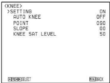
SETTING
When SETTING is set to ON, the high brightness area of the picture is compressed.
SETTING is set to OFF automatically when SELECT in the GAMMA setting is set to CINE1, CINE2, CINE3, or CINE4.
SETTING is set to ON automatically when CINE1, CINE2, CINE3, or CINE4 GAMMA setting is changed to STD1, STD2, STD3, or STD4.
AUTO KNEE: The level of the KNEE function is set to optimum calculated value automatically by the brightness level of the picture that is shot. When this setting is set to OFF, you can set the level point that the KNEE function is activated manually independently of the brightness level of the picture that is shot. This function is not available when SETTING is set to OFF.
POINT: Adjusts the knee point when AUTO KNEE is set to OFF. The adjustable range is 50 to 109 (%). This function is not available when AUTO KNEE is set to ON.
SLOPE: Adjusts the slant of KNEE (degree of compression) when AUTO KNEE is set to OFF. The adjustable range is -99 to +99. This function is not available when AUTO KNEE is set to ON.
KNEE SAT LEVEL: Adjusts the color condition of the higher area than the knee point. The adjustable range is 0 to 99. This function is not available when SETTING is set to OFF.
GAMMA Menu
The GAMMA menu is used to adjust the gamma correction and master black.
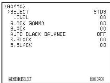
SELECT
Select the gamma correction curve. Select items from STD1, STD2, STD3, STD4, CINE1, CINE2, CINE3, and CINE4.
STD1: The contrast of the dark area is lower than STD2, and the contrast of the middle area is higher than STD2.
STD2: The contrast of the dark area is lower than STD3. STD3: Standard setting.
STD4: The contrast of the dark area is higher than STD3.
CINE1: The contrast of the dark area is gentle and tonal change of the bright area is clear. The picture becomes calm.
CINE2: Almost the same effect as CINE1. For using the picture within 100% video signal when editing, select this setting.
CINE3: The contrast of the dark and bright area is higher than CINE1 and CINE2 and tonal change of the black side is clear.
CINE4: The contrast of the dark area is higher than CINE3. The contrast of the dark area is lower than STD, the contrast of the bright area is higher than STD.
When CINE1, CINE2, CINE3, or CINE4 is set, KNEE SETTING is set to OFF automatically.
When the CINE1, CINE2, CINE3, or CINE4 setting is changed to STD1, STD2, STD3, or STD4, KNEE SETTING is set to ON automatically.
LEVEL: Adjusts the level of the gamma correction curve. The adjustable range is -99 to +99. The larger the setting level, the stronger the correction. The lower the setting level, the weaker correction.
BLACK GAMMA
Adjusts the level of the black gamma function that makes the tone clear by enhancing only the dark area of the picture, or noise to be decreased by weakening the dark area. The adjustable range is -99 to +99. The larger the setting level, the clearer the tone of the dark area. The lower the setting level, the noise decreases by the weakening of the dark area.
BLACK
Adjusts the master black level. The adjustable range is -99 to +99. The larger the setting level, the higher the black level. The lower the setting level, the lower the black level.
AUTO BLACK BALANCE
Readjusts the black level of the video signal.
The video signal will be adjusted to an appropriate black level automatically by pressing the HOME button on the remote controller after the function is set to ON.
R.BLACK
Adjusts the black level of the Rch.
The adjustable range is -99 to 0 to +99.
When the AUTO BLACK BALANCE function is performed, the value will be returned to 0.
B.BLACK
Adjusts the black level of the Bch.
The adjustable range is -99 to 0 to +99.
When the AUTO BLACK BALANCE function is performed, the value will be returned to 0.
FLICKER CANCEL Menu
The FLICKER CANCEL menu is used to adjust the flicker cancel function.
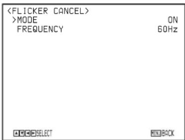
MODE
When this item is set to ON, the flicker cancel function works. When this item is set to OFF, the flicker cancel function does not work.
FREQUENCY
Sets the utility frequency of light source that causes the flicker. Select 50Hz or 60Hz.
Note
Depending on the lighting type or shutter speed, etc., the flicker cancel function may not reduce flicker effectively. If the frame rate of the picture is close to the utility frequency, flicker is not canceled even if the flicker cancel function works properly. In this case, use the electronic shutter.
It is recommended that MODE is set to OFF when shooting under light that does not flicker, such as outdoors.

FOCUS Menu
The FOCUS menu is used to select the focus mode.
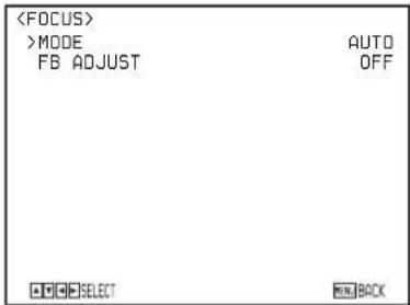
MODE (focus mode)
Select the focus adjustment mode.
AUTO: The focus is adjusted automatically.
MANUAL: Adjust the focus manually. Use the FAR/NEAR buttons on the supplied Remote Commander to adjust the focus.
Note
Adjust the focus manually by setting MODE to MANUAL when the noise increases because the gain level is high or when you shoot:
- a flat subject with low contrast such as a white wall.
• a subject through glass.
• a lateral-striped subject. - a subject exposed to strong light with an illumination, reflecting light, etc.
- a subject with a dark background with flashing lights, such as a night view.
FB ADJUST (Flange back adjustment)
When automatic adjustment of the flange back is performed, this function performs focus adjustment of the wide-angle end and the telephoto end of the zoom lens respectively.
This function also adjusts the flange back and saves the results so that the focus will be kept even if a zoom position is changed after adjusting the focus.
Preparation
Place the camera on a flat surface such as table, and adjust the tilt angle so that the optical axis of the camera becomes horizontal.
Place an object with a clear contrast such as a chart for flange back adjustment at a distance of approx. 3 m, and then adjust the object to be in the screen center at the telephoto end.
At that time, be sure that any subjects closer than the objects cannot be projected in the screen of the wide-angle end.
Adjust the brightness so that an appropriate image outputs.
Adjustment
When you press the HOME button after setting FB ADJUST to ON, flange back adjustment is automatically performed.
When the adjustment is completed, the PLEASE RESTART SYSTEM message displays.
Reboot the camera after turning OFF the POWER of the camera.
If the flange back adjustment is not performed properly, perform it again.
Notes
- If the camera and the optical axis of the camera are not kept horizontally, the flange back adjustment does not work properly.
- Do not perform the flange back adjustment while the camera and the optical axis are inclined.
- If you use a low contrast object, and move the camera and the objects during adjustment, the adjustment cannot be performed properly.
- Do not touch the camera lens and body until the adjustment is completed after starting adjustment.
- Be careful that light sources such as a luminaire, sunlight, or a bright window are not projected in the image frame during the flange back adjustment.
PAN TILT Menu
The PAN TILT menu is used to select the pan/tilt/zoom mode.
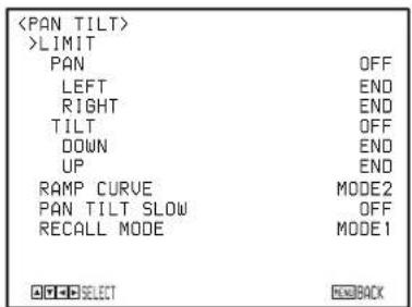
PAN-TILT LIMIT
When you set PAN to ON, you can select the limit of pan operation with the LEFT and RIGHT setting items. When you set TILT to ON, you can select the limit of tilt operation with the UP and DOWN setting items. You can select the following values:
PAN LEFT: END, 169° to -169°, by intervals of 1° PAN RIGHT: END, -169° to 169°, by intervals of 1° TILT DOWN: END, -29° to 89°, by intervals of 1° TILT UP: END, 89° to -29°, by intervals of 1°
Setting range of PAN LEFT/PAN RIGHT
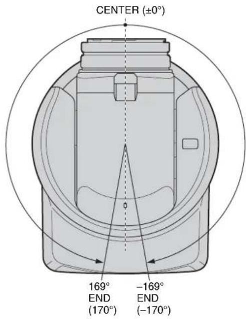
Setting range of TILT DOWN/TILT UP
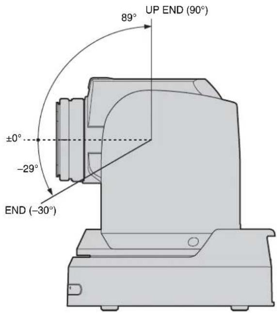
Notes
- Before storing the camera position in a preset memory, perform the PAN-TILT LIMIT setting. If the camera position is not within the range of the PAN-TILT LIMIT setting, you cannot store the camera position in the preset memory.
- The PAN-TILT LIMIT setting is reset to the factory setting when you change IMG FLIP of the SYSTEM menu.
- Before storing the camera position in a preset memory, install the camera suitably and fix the camera securely. If you change the installation of the camera after presetting, differences may arise on the preset.
RAMP CURVE
Select the panning and tilting speed acceleration or reduction mode when the preset panning and tilting operation is recalled.
MODE1: Panning/tilting speed accelerates or reduces sharper than MODE2.
MODE2: Panning/tilting speed accelerates or reduces with standard response.
PAN TILT SLOW (Slow Pan-Tilt)
You can select the maximum speed for the pan/tilt operations.
OFF: Pan/tilt operates at a standard speed.
ON: Pan/tilt operates at a slower speed than the standard.
RECALL MODE (Recall mode)
You can select the order for the pan/tilt/zoom operations when the camera moves to a PRESET position.
MODE1: When the camera moves to a PRESET position, the pan/tilt/zoom operations start at the same time.
MODE2: When the camera moves to a PRESET position, after the pan/tilt operations are finished, the zoom operation starts.
SYSTEM Menu
| IR RECEIVE | ON |
| IMG FLIP | OFF |
| PAN REVERSE | OFF |
| TILT REVERSE | OFF |
| >DISPLAY INFO | ON |
| SYNC MASTER | HD |
| HPHASE | 03 |
| HPHASE FINE | 0 |
| STEADY SHOT | OFF |
| COLOR BAR | OFF |
| TALLY MODE | LOW |
| PRESET MODE | MODE1 |
| VERSION | 1.00 |
IR RECEIVE (infrared signal reception)
When it is set to OFF, the camera does not receive the signal from the supplied Remote Commander.
Be sure to keep it ON when you use the supplied Remote Commander.
Note
You cannot set IR RECEIVE to OFF when you operate the menu using the supplied Remote Commander. To set it to OFF, use the RM-BR300 Remote Control Unit (not supplied) or the VISCA command.
IMG FLIP (image flip)
Set IMG FLIP to ON to rotate the camera image supplied from the RGB/COMPONENT,
S VIDEO, ➕ VIDEO, and SDI OUT connector and the connector on the optional Interface Card inserted into the card slot upside down and to reverse the direction of the camera movement by pan/tilt operation.
Set PAN REVERSE to ON to reverse the horizontal movement of the camera image.
Set TILT REVERSE to ON to reverse the vertical movement of the camera image.
When you set IMG FLIP to ON, "Please restart system!" appears. Turn off the power of the camera, then turn it on again.
Notes
- Regardless of the IMG FLIP ON/OFF setting, images shot by the camera are accumulated for the vertical synchronization period and output from the RGB/COMPONENT, S VIDEO, ⇔ VIDEO, and SI OUT connector of the camera and the connector on the optional Interface Card inserted into the card slot.
- When you set IMG FLIP to ON, turn off the camera, then turn it on again, PAN REVERSE and TILT REVERSE will be set to ON. When you set IMG FLIP to OFF, turn the power off, then on again, PAN REVERSE and TILT REVERSE will be set to OFF.
DISPLAY INFO (information display)
When the camera settings are stored in POSITION 1 to 16 using the supplied Remote Commander or the RM-BR300 Remote Control Unit, the message "PRESET No. xx" automatically appears for two seconds on the monitor screen. If you want to display the message each time the camera is operated, set DISPLAY INFO to ON. Set it to OFF to cancel the display.
Note
The message will appear if the built-in cooling fan of the camera has accidentally stopped. When DISPLAY INFO is set to OFF, the display of this message is also canceled.
SYNC MASTER
When you connect a sync signal generator, you can select an output video signal that is synchronized with the external video sync signal input to the EXT SYNC IN connector on the camera.
When connecting the BRU-SF10 HD Optical Multiplex Unit, select an output video signal that is synchronized with the external video sync signal input to the EXT SYNC IN connector on the BRU-SF10 HD Optical Multiplex Unit.
HD: Selects the output signal from the RGB/COMPONENT connector.
SD: Selects the output signal from the VIDEO or S VIDEO connector.
When outputting from the SDI connector, select "HD" for HD-SDI signal, or "SD" for SD-SDI signal.
H PHASE
When you connect a sync signal generator, adjust the phase difference between the external video sync signal input to the EXT SYNC IN connector on the camera and video signal of the camera. The adjustable range is from 0 to 959 STEP.
The video signal advances for + setting, delays for - setting from the external video sync signal. Adjust following items.
HPHASE: Adjusts in 10 STEP (about 0.1347 μsec). The adjustable range is 00 to 95.
HPHASE FINE: Adjusts in 1 STEP (about 0.01347 μsec).
The adjustable range is 0 to 9.
When you set more than 9, the HPHASE value increases 1 and HPHASE FINE value returns to 0 automatically.
When you set to less than 0, the HPHASE value decreases in 1 and HPHASE FINE value returns to 9 automatically.
Note
HPHASE and HPHASE FINE does not appear when a BRU-SF10 HD Optical Multiplex Unit is in use.
STEADY SHOT
You can select the effects of picture blur compensation depending on shooting conditions.
OFF: Disables the picture blur compensation.
ON: The picture blur compensation is activated.
Notes
- This function does not work while the camera is panning or tilting. After panning or tilting is stopped, it may take some time to stabilize the picture.
- It may take some time to obtain stable images after turning on the camera when STEADY SHOT is activated.
- Picture blur compensation may not work depending on installation conditions.
COLOR BAR
When this item is set to ON, the built-in color bar of the camera is displayed on the monitor screen.
TALLY MODE
Adjusts setting of the tally lamp on the front and back on the camera. Select from HIGH, LOW, or OFF.
HIGH: Makes the front tally lamp bright when the tally lamp is turned on.
LOW: Makes the front tally lamp dim when the tally lamp is turned on.
OFF: Both the front and back tally lamps are not turned on even if the ON command for the tally lamp is received.
Note
When the TALLY MODE is set to OFF, both the front and back tally lamp are not turned on.
You cannot adjust the brightness of the back tally lamp. The brightness of the back tally lamp is same for the HIGH or LOW setting.
PRESET MODE (Preset mode)
You can select the items to be stored in the PRESET.
MODE1: Stores the positions of the pan/tilt/zoom and the setting items ^1) of the camera at the same time.
MODE2: Stores the positions of the pan/tilt/zoom and the focus position (only when set to MANUAL mode).
^1) For details of the camera settings to be preset, see “Presetting Items” on page 79.
VERSION
Information for the firmware version of BRC-H900.
VIDEO OUT Menu
![HD-RGB/COMPONENT >FORMAT YPbPr SYNC TYPE #SYNC SD-VIDEO/S VIDEO IMG SIZE 16:9[LETTER] SETUP OFF SELECT RENEWBACK](/content/2026/03/486734/images/c7293c0809f61cb1ef30f2896434339b67beefdf9e104e95c72192ffdada4cff.jpg)
HD-RGB/COMPONENT
FORMAT
Select the signal output from the RGB/COMPONENT connector on the camera.
YPbPr: Outputs analog component signals.
RGB: Outputs RGB signals.
ADD SYNC
Appears when RGB is selected with FORMAT and specifies whether to add a sync signal.
RGB: Outputs each R, G and B signal with a sync signal added.
OFF: Outputs each R, G and B signal with no sync signal added.
SYNC TYPE
Appears when either RGB or YPbPr is selected with FORMAT and specifies the type of a sync signal.
^1 SYNC: Outputs the tri-level sync.
VD: Outputs the bi-level sync.
SD-VIDEO/S VIDEO
IMG SIZE
Select the aspect ratio of the signal output from the VIDEO or · SVIDEO connector on the camera.
16:9[LETTER]: The image is displayed in 16:9 letterbox.
4:3[CROP]: The image is displayed in 4:3 edge crop.
4:3[SQUEEZE]: The image is displayed in 4:3 squeeze.
Note
If the SDI output on the camera is set to SD, IMG SIZE of the SD-SDI output is also changed when IMG SIZE is changed.
SETUP
Select whether 7.5IRE setup is added to the signal output from the VIDEO or S VIDEO connector on the camera.
ON: Outputs signals with 7.5IRE setup added.
OFF: Outputs signals with no 7.5IRE setup added.
Notes
- The SETUP item does not appear when an HD signal of 1080/50i or 720/50p format is output.
- 7.5IRE setup is not added to output signals from the SD-SD1 output.
SD-SDI Menu
This menu only appears when an optional BRBK-HSD2 HD/SD-SDI Output Card is installed in the BRC-H900 HD Color Video Camera or in the BRU-SF10 HD Optical Multiplex Unit, and the panel switch on the card is set to SD.
![>IMG SIZE 16:9[LETTER] SELECT NO BACK](/content/2026/03/486734/images/a70b945f9ca877d1fa008b68a9f1f94e1a6abdf0dffb223d2e0f59a09ffca4da.jpg)
IMG SIZE
Select the aspect ratio of the output signal.
16:9 [LETTER]: The image is displayed in 16:9 letterbox.
4:3 [CROP]: The image is displayed in 4:3 edge crop.
4:3 [SQUEEZE]: The image is displayed in 4:3 squeeze.
Notes
- When a BRBK-HSD2 HD/SD-SDI Output Card is installed in the BRC-H900 HD Color Video Camera, the IMG SIZE settings in the SD-SDI menu and VIDEO OUT menu are linked.
- If you change the IMG SIZE setting in the SD-SDI menu, the IMG SIZE setting for outputs from the VIDEO and S VIDEO connectors on the BRC-H900 HD Color Video Camera will also change.
- If you change the IMG SIZE setting in the VIDEO OUT menu, the IMG SIZE setting for SD-SDI outputs from the BRBK-HSD2 HD/SD-SDI Output Card will also change.
SD Menu
This menu only appears when an optional BRBK-SA1 Analog SD Output Card is installed in the BRC-H900 HD Color Video Camera or in the BRU-SF10 HD Optical Multiplex Unit.
![>D-SUB OUTPUT1 YCbCr D-SUB OUTPUT2 VBS IMG SIZE 16:9[LETTER] SETUP OFF SELECT BACK](/content/2026/03/486734/images/409596d2ece1cfe15d7a5ef0a8aeddf8324e9b3c68d2d9c7288befbf5c96dc84.jpg)
D-SUB OUTPUT1
Select the signal output from the RGB/SYNC connector (D-sub 9-pin) on the BRBK-SA1 Analog SD Output Card.
YCbCr: Outputs analog component signals.
RGB: Outputs RGB signals.
ADD SYNC
Appears when RGB is selected with D-SUB OUTPUT1 and specifies whether to add a sync signal.
RGB: Output R, G, and B signals with a sync signal added.
OFF: Output R, G, and B signals with no sync signal added.
D-SUB OUTPUT2
Select the signal output from the RGB/SYNC connector (D-sub 9-pin) on the BRBK-SA1 Analog SD Output Card.
VBS: Outputs analog composite signals.
Y/C: Outputs S-video signals.
IMG-SIZE (image size)
Select the aspect ratio of the output signal.
16:9[LETTER]: The image is displayed in 16:9 letterbox.
4:3[CROP]: The image is displayed in 4:3 edge crop.
4:3[SQUEEZE]: The image is displayed in 4:3 squeeze.
Notes
- When a BRBK-SA1 Analog SD Output Card is installed in the BRC-H900 HD Color Video Camera,
the IMG SIZE settings in the SD menu and VIDEO OUT menu are linked.
- If you change the IMG SIZE setting in the SD menu, the IMG SIZE setting for outputs from the VIDEO and S VIDEO connectors on the BRC-H900 HD Color Video Camera will also change.
- If you change the IMG SIZE setting in the VIDEO OUT menu, the IMG SIZE setting for all outputs from the BRBK-SA1 Analog SD Output Card will also change.
SETUP
Select whether 7.5IRE setup is added to output signals. When ON is selected, setup signals are added to all image signals except YCbCr.
ON: Outputs signals with 7.5IRE setup added.
OFF: Outputs signals with no 7.5IRE setup added.
Note
The SETUP item does not appear when an HD signal of 1080/50i or 720/50p format is output.
Operation Using the Supplied Remote Commander
Before operating, check that the camera and peripheral devices are properly installed and connected.
For details, see “Installation” (page 56) and “Connections” (page 64).
Turning on the Power
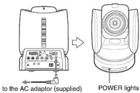
1 Connect the camera to an AC outlet using the supplied AC power adaptor and power cord.
The power is turned on and the POWER lamp lights.
The camera will automatically pan and tilt and be reset to the position stored in POSITION 1 (Pan/tilt reset action).
2 Turn on the peripheral devices.
To turn on/off the camera using the Remote Commander
As long as the camera is connected to an AC outlet, you can turn the camera on or off with the POWER button on the Remote Commander.
When you turn the power off using the Remote Commander, the POWER lamp turns off and the STANDBY lamp lights on the camera.
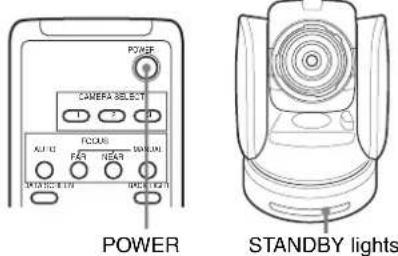
Pan/Tilt and Zoom Operation
Panning and Tilting
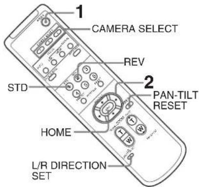
1 Press the POWER button.
The camera will turn on and perform the pan/tilt reset action automatically.
2 Press the arrow button to pan or tilt the camera. While checking the picture on the screen, press the appropriate arrow button.
To move the camera little by little, press the button just for a moment.
To move the camera in a wide range, press and hold the button.
To move the camera diagonally, press the or button while holding down the or button.
To face the camera back to the front
Press the HOME button.
If you accidentally move the camera with your hand
Press the PAN-TILT RESET button to perform the pan/tilt reset action.
If the camera moves in a different direction from that you intended
The camera is preset to face toward the right whenever the ➤ button is pressed. You might wish to face the camera toward the opposite direction from that of the button you pressed, for example, when you change the direction of the camera while checking the picture on the screen. In such a case, press the 2 (REV) button while holding down the L/R DIRECTION SET button.
To reset the setting, press the 1 (STD) button while holding down the L/R DIRECTION SET button.
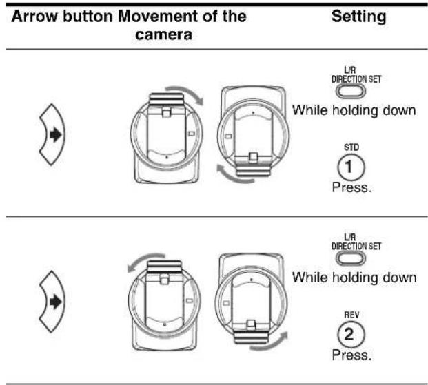
Note
The setting above only changes the signal emitted from the Remote Commander, and does not change the setting of the camera itself. Therefore, repeat the setting for each Remote Commander if you are using more than one Remote Commander.
If the STANDBY lamp of the camera flashes
When the camera is moved or turned by hand or by external shock, the microcomputer inside the camera may not be able to memorize the pan/tilt position properly and the camera may stop. To reset the pan/tilt position, press the PAN-TILT RESET button or turn the power of the camera off, then turn it on again.
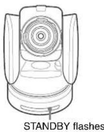
natural_image
Line drawing of a Standby flash device (no text or symbols on the diagram itself)Zooming
Press either of the ZOOM buttons.
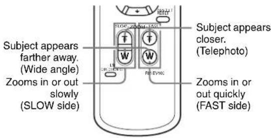
Note
When you perform pan/tilt operation while the camera is in the telephoto mode, the moving speed of the image on the screen may be a little jerky.
Operating Multiple Cameras with the Remote Commander
1 Set the IR SELECT switch on the rear of the camera you want to operate to 1, 2 or 3.
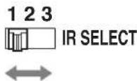
2 Press the CAMERA SELECT button on the Remote Commander that corresponds to the number set in step 1.
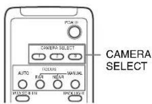
You can then operate the camera(s) specified by number. Every time you operate the camera(s) using the Remote Commander, the CAMERA SELECT button pressed in step 2 lights.
Adjusting the Camera
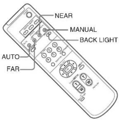
Focusing on a Subject
To focus the camera on a subject automatically
Press the AUTO button.
The camera focuses on the subject at the center of the screen automatically.
To focus the camera on a subject manually
After pressing the MANUAL button, press either the FAR or the NEAR button to have the camera focus on the subject.
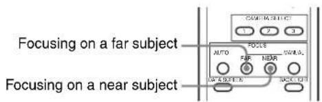
Shooting with Back Lighting
When you shoot a subject with a light source behind it, the subject becomes dark. In such a case, press the BACK LIGHT button.
To cancel the function, press the BACK LIGHT button again.
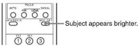
Note
The BACK LIGHT function is effective if MODE is set to FULL AUTO or BACK LIGHT in the EXPOSURE menu of the camera.
Storing the Camera Settings in Memory
- Presetting Feature
Up to six combinations of settings (six positions) including camera position, zooming, focusing, and backlighting, can be preset.
Note
The camera can store up to sixteen combinations of settings (sixteen positions) in the memory, but the supplied Remote Commander supports preset of six positions only (POSITION 1 to 6). Use the RM-BR300 Remote Control Unit (not supplied) to store the settings in POSITION 7 to 16.
For details of the camera settings to be preset, see “Presetting Items” on page 79.
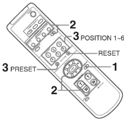
1 Press the PAN-TILT RESET button to reset the pan/tilt position.
2 Adjust the position, zooming, focusing and backlighting of the camera (pages 45 to 47).
3 While holding down the PRESET button, press any of the POSITION buttons, 1 to 6, in which you want to store the settings.

The message “PRESET No.xx” (selected POSITION number) is displayed for about 2 seconds.
Note
Before you store camera settings such as camera position, zooming, focusing, etc., in the memory, install the camera suitably and fix the camera securely. If you change the installation of the camera after storing, differences may arise on the preset.
To recall the stored settings
Press any of the POSITION buttons, 1 to 6, in which you have stored the settings.
To cancel the preset memory
While holding down the RESET button, press the POSITION button from which you want to cancel the settings.

Notes
- When the power is turned on, the camera starts with the settings stored in POSITION 1.
- If you want to retain the previous pan and tilt positions, etc., when the power is turned off and turned on again, store those positions in POSITION 1.
- Storing or canceling the settings in POSITION 1 takes about two seconds longer than those of other positions.
- When you are storing or canceling the settings in one POSITION, you cannot call up, store or cancel the settings in another POSITION.
- For details about the memory that you can erase, see "Presetting Items" on page 79.
Operation Using the RM-BR300 Remote Control Unit
Before operating, check that the camera, the RM-BR300 Remote Control Unit and peripheral devices are properly installed and connected.
For details, see “Installation” (page 56) and “Connections” (page 64).
Turning on the Power
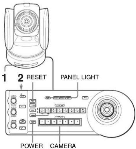
1 Connect the camera to an AC outlet using the supplied AC power adaptor and power cord. The power is turned on and the POWER lamp lights.
The camera will automatically pan and tilt and be reset to the position stored in POSITION 1 (Pan/tilt reset action).
2 Press the ON/OFF switch on the RM-BR300 Remote Control Unit to turn it on.
A CAMERA button lights to represent the camera whose power was turned off last. (The CAMERA 1 button lights by default.)
3 Turn on the peripheral devices.
Note
Be sure to turn on the power of the camera before the power of the Remote Control Unit. Otherwise, the Remote Control Unit cannot recognize the connected camera.
To turn on/off the camera using the RM-BR300 Remote Control Unit
As long as the camera is connected to an AC outlet, you can turn the camera on or off with the POWER button on the Remote Control Unit.
While holding down the POWER button, press the CAMERA button corresponding to the camera whose power you want to turn on/off.
When you turn the power off using the Remote Control Unit, the POWER lamp turns off and the STANDBY lamp lights on the camera.
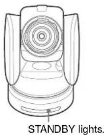
To illuminate the panel of the Remote Control Unit
Press the PANEL LIGHT button. All the POSITION buttons and CAMERA buttons light. To turn off the illumination, press the PANEL LIGHT button again.

Operating Multiple Cameras
Before operating, you must assign the camera addresses to the connected cameras as follows. Then you can switch the camera to be controlled simply by pressing the corresponding CAMERA button.
To assign camera addresses automatically
1 Make sure that the camera address selector on the bottom of each camera is set to "0."
For setting the camera address selector, see page 19.
2 Turn on the power of all the connected cameras and the RM-BR300 Remote Control Unit.
3 Hold down the RESET button and press the POWER button on the Remote Control Unit. The Remote Control Unit recognizes the connected cameras and assigns them camera addresses 1 to 7 automatically in the connected order.
4 Press the POWER button on the Remote Control Unit and check that the CAMERA buttons light. The number of the lit CAMERA buttons indicates how many cameras have the addresses assigned. Now you can switch the camera you want to control with the Remote Control Unit by pressing the CAMERA button.
To assign camera addresses manually
Set one of the camera addresses, 1 to 7, using the camera address selectors on the bottom of each camera.
For setting the camera address selectors, see page 19.
Pan/Tilt and Zoom Operation
Panning and Tilting
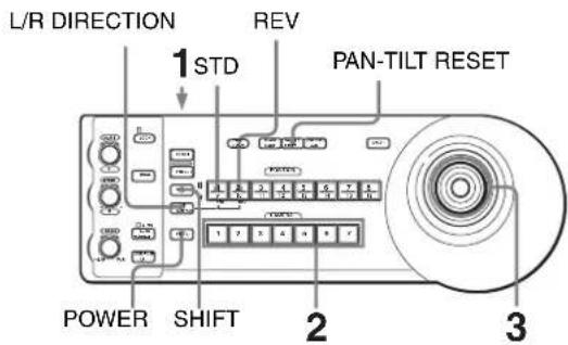
1 Turn on the power of the camera and the RM-BR300 Remote Control Unit. The camera will turn on, performing the pan/tilt reset action automatically.
2 Press the CAMERA button corresponding to the camera you want to operate.
3 Operate the joystick to pan or tilt the camera. While checking the picture on the screen, incline the joystick in the desired direction. The panning/tilting speed changes according to the angle at which you incline the joystick. Release the joystick to stop panning/tilting.
To set a limit on the maximum panning/tilting speed
You can limit the panning/tilting speed obtained when you incline the joystick at the maximum angle.
1 Hold the PAN-TILT RESET button for more than a second while pressing the SHIFT button. All of the CAMERA buttons 1 to 7 flash.
2 Press the CAMERA button corresponding to the speed you want to set, as shown in the table below.
| CAMERA button Maximum panning/tilting speed |
| 1 3.5 degrees/sec. |
| 2 6.4 degrees/sec. |
| 3 11 degrees/sec. |
| 4 18.3 degrees/sec. |
| 5 29 degrees/sec. |
| CAMERA button Maximum panning/tilting speed |
6 43 degrees/sec.
7 60 degrees/sec.
Only the CAMERA button you pressed flashes, and the corresponding maximum panning/tilting speed is set.
Note
The maximum panning/tilting speed setting is stored in the memory of the optional RM-BR300 Remote Control Unit. If you use another RM-BR300 Remote Control Unit or you connect another camera to the RM-BR300, set a limit on the maximum panning/tilting speed again.
To face the camera back to the front
Press the button on the top of the joystick for one or two seconds.
Press for 1 or 2 seconds.
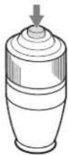
If you accidentally move the camera with your hand
Press the PAN-TILT RESET button to perform the pan/tilt reset action.
If the camera moves in a different direction from that you intended
The camera is preset to face toward the right whenever the joystick is inclined to the right. You might wish to face the camera toward the opposite direction from that in which you inclined the joystick, for example, when you change the direction of the camera while checking the picture on the screen. In such a case, press the POSITION 2 (REV) button while holding down the L/R DIRECTION button.
To reset the setting, press the POSITION 1 (STD) button while holding down the L/R DIRECTION button.
| Joystick Movement of the camera | Setting |
Incline to the right.
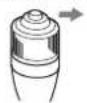
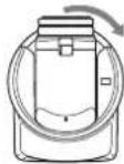
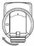
e holding down


Press.
Incline to the right.

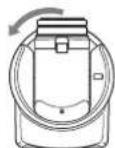
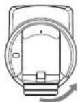
While holding down


Press.
Note
The setting above only changes the signal emitted from the RM-BR300 Remote Control Unit, and does not change the setting of the camera itself.
If the STANDBY lamp of the camera flashes
When the camera is moved or turned by hand or by external shock, the microcomputer inside the camera may not be able to memorize the pan/tilt position properly.
To reset the pan/tilt position, press the PAN-TILT RESET button.
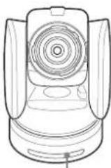
STANDBY flashes.
Zooming
Turn the dial on the upper part of the joystick.
Subject appears farther away. (Wide angle)
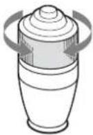
Subject appears closer. (Telephoto)
Note
When you perform pan/tilt operation while the camera is in the telephoto mode, the moving speed of the image on the screen may be a little jerky.
Adjusting the Camera
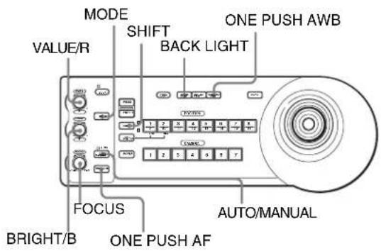
Focusing on a Subject
To focus the camera on a subject automatically
Press the AUTO/MANUAL button so that the AUTO indicator lights.
The camera focuses on the subject in the center of the screen automatically.
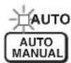
To focus the camera on a subject manually
Press the AUTO/MANUAL button so that the AUTO indicator turns off.
Then turn the FOCUS control clockwise or counterclockwise to have the camera focus on the subject.
Focusing on a near subject

Focusing on a far subject
One-push auto focusing during manual focus adjustment
Press the ONE PUSH AF button.
The camera focuses on the subject in the center of the screen automatically.

Shooting with Back Lighting
When you shoot a subject with a light source behind it, the subject becomes dark. In such a case, press the BACK LIGHT button.
To cancel the function, press the BACK LIGHT button again.

Note
The BACK LIGHT function is effective if MODE is set to FULL AUTO or BACK LIGHT in the EXPOSURE menu of the camera. Each time you press the button, the BACK LIGHT function toggles between on and off.
Shooting with spotlight compensation
If a portion of the shooting object is illuminated, the spotlight compensation function adjusts the exposure to a darker level. Hold down the SHIFT button and press the BACK LIGHT button.
To cancel the function, hold down the SHIFT button and press the BACK LIGHT button again.
Notes
- The backlighting and spotlight compensation functions cannot be used simultaneously.
- The spotlight compensation function is effective if MODE is set to FULL AUTO or SPOT LIGHT in the EXPOSURE menu of the camera. Each time you press the button, the BACK LIGHT function toggles between on and off.
Adjusting the White Balance
Before adjusting the white balance, shoot a white object under the same lighting conditions as the subject you want to shoot, and zoom it in on the screen. (You can use a white wall, etc., instead of the object.)
To adjust the white balance automatically
1 Set WHITE BALANCE to ONE PUSH in the COLOR menu of the camera.
For setting, see "COLOR Menu" on page 33.
2 Press the ONE PUSH AWB button. The white balance is adjusted automatically.

To adjust the white balance manually
1 Set WHITE BALANCE to MANUAL in the COLOR menu of the camera.
For setting, see "COLOR Menu" on page 33.
2 Press the MODE button so that the R and B indicators on the VALUE/R and BRIGHT/B controls light (white balance adjustment mode).
3 Adjust the red gain with the R control and the blue gain with the B control.
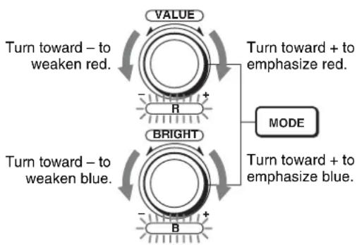
flowchart
graph TD
    A["VALUE"] --> B["Turn toward - to weaken red."]
    B --> C["R"]
    C --> D["+"]
    D --> E["BRIGHT"]
    E --> F["Turn toward - to weaken blue."]
    F --> G["-"]
    G --> H["B"]
    H --> I["+"]
    I --> J["MODE"]
    J --> K["Turn toward + to emphasize blue."]
Functions of the R and B controls
When the white balance adjustment mode is selected with the MODE button on the Remote Control Unit, the functions of the R control and B control change according to the WHITE BALANCE setting in the COLOR menu of the camera.
| WHITE BALANCE setting | R control B control |
| MANUAL Red gain control Blue gain control | |
| AUTO, ONE PUSH | OFFSET control OFFSET control |
Adjusting the Brightness
1 Set MODE to SHUTTER Pri, IRIS Pri, GAIN Pri or MANUAL in the EXPOSURE menu of the camera.
For setting, see "EXPOSURE Menu" on page 32.
2 Press the MODE button so that the VALUE and BRIGHT indicators on the VALUE/R and BRIGHT/B controls light (Brightness adjustment mode).
3
Adjust the brightness with the VALUE or BRIGHT control.
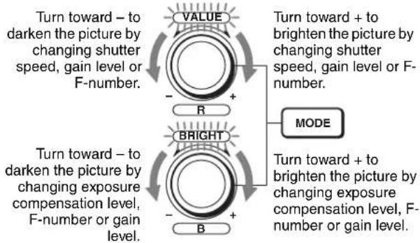
flowchart
graph TD
    A["VALUE"] --> B["R"]
    C["BRIGHT"] --> D["B"]
    E["MODE"] --> F["+"]
    G["Turn toward + to brighten the picture by changing shutter speed, gain level or F-number."] --> H["+"]
    I["Turn toward - to darken the picture by changing exposure compensation level, F-number or gain level."] --> J["-"]
    K["Turn toward + to brighten the picture by changing exposure compensation level, F-number or gain level."] --> L["-"]
Functions of the VALUE and BRIGHT controls The functions of the VALUE control and the BRIGHT control change according to the MODE setting in the EXPOSURE menu, as follows:
| MODE setting | Function of VALUE control | Function of BRIGHT control |
| FULL AUTO Not used AE LEVEL | ||
| SHUTTER Pri | Shutter speed control | AE LEVEL |
| IRIS Pri F-number control AE LEVEL | ||
| GAIN Pri Gain control AE LEVEL | ||
| MANUAL Shutter speed control | F-number and gain controls (when the DIP switch 3 at the bottom of the Remote Control Unit is set to ON)F-number control (when the DIP switch 3 at the bottom of the Remote Control Unit is set to OFF) | |
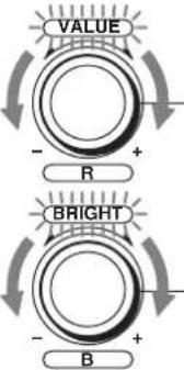
Storing the Camera Settings in Memory – Presetting Feature
Up to sixteen combinations of settings (sixteen positions), including camera position, zooming, focusing, and backlighting, can be stored in the memory of the camera using the RM-BR300 Remote Control Unit.
For details of the camera settings to be preset, see "Presetting Items" on page 79.
Storing Camera Settings
To select positions 9 to 16
While holding down the SHIFT button, press the PRESET button (to store the settings) or the RESET button (to cancel the settings). The lower indicator on the SHIFT button will light and the POSITION 1 to 8 buttons can be used for positions 9 to 16. When you release the SHIFT button, the upper indicator lights and the POSITION 1 to 8 buttons can be used for positions 1 to 8.

To store camera settings
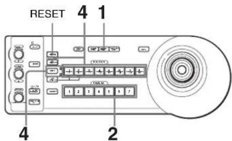
1 Press the PAN-TILT RESET button to reset the pan/tilt position.
2 Press the CAMERA button to select the camera whose settings you want to preset.
3 Adjust the position, zooming, focusing and backlighting of the camera. (See page 50 to 53.)
4
While holding down the PRESET button (for POSITION 1 to 8) or the SHIFT and PRESET buttons (for POSITION 9 to 16), press any of the POSITION buttons in which you want to store the settings.
While holding down (for POSITION 1 to 8)
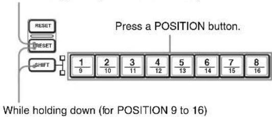
flowchart
graph TD
    A["RESET"] --> B["SHIFT"]
    C["RESET"] --> B
    D["SHIFT"] --> E["1/9"]
    F["SHIFT"] --> G["2/10"]
    H["SHIFT"] --> I["3/11"]
    J["SHIFT"] --> K["4/12"]
    L["SHIFT"] --> M["5/13"]
    N["SHIFT"] --> O["6/14"]
    P["SHIFT"] --> Q["7/15"]
    R["SHIFT"] --> S["8/16"]
    T["Press a POSITION button."] --> U["1/9"]
    V["While holding down (for POSITION 9 to 16)"] --> W["2/10"]
The settings are stored in the memory of the camera.
The pressed button flashes during storing. Flashing stops when storing is completed.
To recall the stored settings
Press any of the POSITION buttons in which you have stored the settings.
For POSITION 9 to 16, hold down the SHIFT button and press any of the POSITION buttons.
To cancel the preset memory
While holding down the RESET button (for POSITION 1 to 8) or the SHIFT and RESET buttons (for POSITION 9 to 16), press the POSITION button from which you want to cancel the settings.
While holding down (for POSITION 1 to 8)
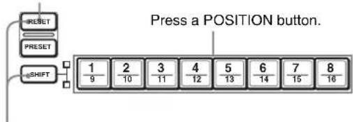
flowchart
graph TD
    A["RESET"] --> B["SHIFT"]
    C["PRESET"] --> B
    D["SHIFT"] --> E["1/9"]
    F["SHIFT"] --> G["2/10"]
    H["SHIFT"] --> I["3/11"]
    J["SHIFT"] --> K["4/12"]
    L["SHIFT"] --> M["5/13"]
    N["SHIFT"] --> O["6/14"]
    P["SHIFT"] --> Q["7/15"]
    R["SHIFT"] --> S["8/16"]
    T["Press a POSITION button."] --> U["1/9"]
While holding down (for POSITION 9 to 16)
The pressed button flashes during canceling of the settings. Flashing stops when the settings have been canceled.
Notes
- When the power is turned on, the camera starts with the settings stored in POSITION 1.
- If you want to retain the previous pan and tilt positions when the power is turned off and turned on again, store those positions in POSITION 1.
- When you are storing or canceling the settings in one POSITION, you cannot call up, store or cancel the settings in another POSITION.
- Before you store camera settings such as camera position, zooming, focusing, etc., in the memory,
install the camera suitably and fix the camera securely. If you change the installation of the camera after storing, differences may arise on the preset.
- For details about the setting items that you can store/ erase, see "Presetting Items" on page 79.
Setting the Speed of the Camera Movement to a Preset Position
You can select the panning/tilting speed when the camera moves to a preset position.
1 Press the CAMERA button to select the camera whose speed you want to set.
2 Press the POSITION button for which you want to set the speed for more than one second. All the CAMERA buttons, 1 to 7, flash.
3 Press one of the CAMERA buttons to select the speed.
CAMERA button Panning/tilting speed
| 1 1 degree/sec. |
| 2 2.2 degrees/sec. |
| 3 4.8 degrees/sec. |
| 4 11 degrees/sec. |
| 5 23.3 degrees/sec. |
| 6 43 degrees/sec. |
| 7 60 degrees/sec. (default) |
Now the camera will move to the position preset to the pressed POSITION button with the selected speed.
To set the camera's movement speed to a preset position between 9 and 16
Hold down the SHIFT button and press the corresponding POSITION button for more than one second. The POSITION 1 to 8 buttons can be used for positions 9 to 16.
Installation and Connections
Installation
Attaching an Interface Card
Attach an Interface Card (not supplied) to the card slot on the rear of the camera.
1 Loosen the two screws to remove the card slot cover.
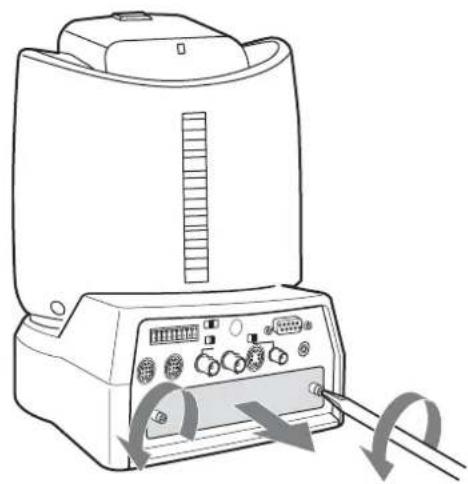
natural_image
Line drawing of a portable electronic device with ports and control panel, showing signal flow arrows (no text or symbols)2 Insert an optional Interface Card into the card slot. Align both ends of the card with the sliders inside the slot, then insert the card securely as far as it will go.
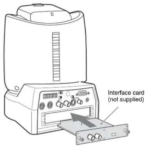
3 Tighten the two screws on the Interface Card.
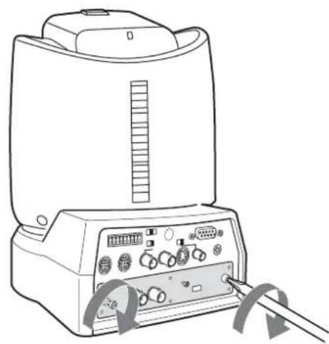
natural_image
Line drawing of a portable electronic device with control panel and buttons (no text or symbols)To remove the Interface Card
Loosen the two screws on the Interface Card and pull the card out straight and slowly.
Installing the Camera
To install the camera on a desk
Place the camera on a flat surface.
If you have to place the camera on an inclined surface, make sure that the inclination is less than ±15 degrees, so that the pan/tilt performance is guaranteed, then ensure the camera does not fall.
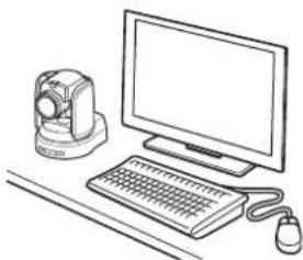
natural_image
Line drawing of a desktop computer setup with monitor, keyboard, mouse, and camera (no text or symbols)Notes
- You should take an appropriate countermeasure to prevent the camera from falling.
- Do not grasp the camera head when carrying the camera.
- Do not turn the camera head by hand. Doing so may result in the camera malfunctioning.
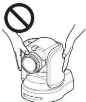
natural_image
Illustration of hands holding a camera with a prohibition symbol above (no text or labels)
natural_image
Illustration of a hand holding a camera with a prohibition symbol (no text or labels)
natural_image
Illustration of a hand using a device to clean or stop it, with no text or symbols present.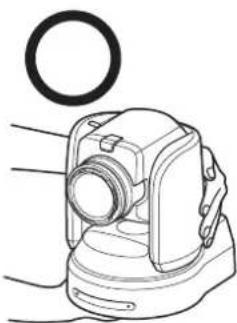
natural_image
Line drawing of a mechanical device with a circular component above it (no text or symbols)To attach the camera to a tripod
Attach a tripod to the tripod screw hole on the bottom of the camera.
The tripod must be set up on a flat surface and tightened firmly by hand.
Use a tripod with screws of the following specifications.
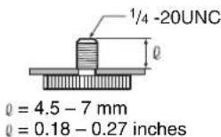
Caution
Installation of the camera using the tripod screws and screw holes should not be done for installation on a ceiling or a shelf, etc., in a high position.
Installing the Camera in a High Position
Using the supplied ceiling brackets, wire rope and screws, and attachment materials (not supplied), you can attach the camera to a ceiling or on a shelf, etc., in a high position.
When you install the camera, always install it on a level surface. If you have to install it on an incline, make sure that the inclination is within ± 15 degrees, so that the pan/tilt performance is guaranteed.
Caution
- When you attach the camera to a ceiling or shelf, etc., in a high position, entrust the installation to an experienced contractor or installer.
- Attach the camera to the ceiling or shelf, etc., firmly, after making sure the surface and the attachment materials (not including the supplied accessories) are strong enough to bear a weight of 60 kg (132 lb 4 oz). If the ceiling or shelf, etc., is not strong enough, the camera may fall and cause serious injury.
- Be sure to attach the supplied wire rope to prevent the camera from falling.
- Check periodically, at least once a year, to ensure that the connection has not loosened. If conditions warrant, make this periodic check more frequently.
Before installation
After deciding the shooting direction, make the required holes for the ceiling bracket (B) and connecting cables on the ceiling or shelf, etc. For the dimensions of the ceiling bracket (B), see page 83.
Notes
- The connecting cables cannot be passed through the ceiling bracket (A). A hole for the wiring is required through the surface on which the camera is to be installed.
- Do not attach any object other than the camera to the ceiling brackets.
- The ceiling bracket cannot be attached to a junction box when installing the camera on a ceiling.
Installation on a ceiling (example)
1 Set IMG FLIP to ON in the SYSTEM menu.
2 Remove the four screws on the bottom of the camera to remove the four feet.
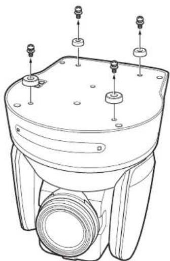
natural_image
Technical line drawing of a mechanical device with mounting holes and internal components (no text or symbols)3
Attach the ceiling bracket (A) to the bottom of the camera using the supplied four screws ( M3 × 8 ). Position the O hole for screwing on the ceiling bracket (A) to the front of the camera as illustrated, align the screw holes on the ceiling bracket with those on the bottom of the camera, then attach the bracket to the camera.
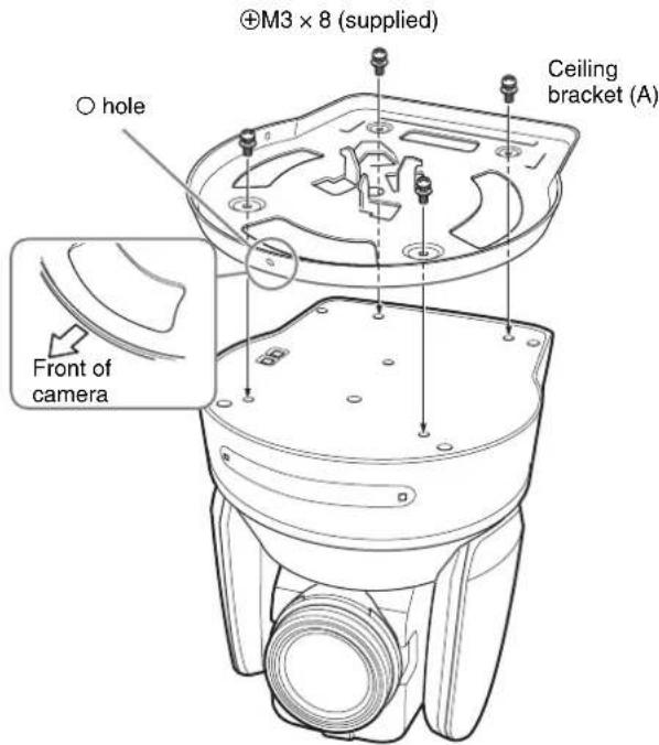
Caution
For attaching the camera to the ceiling bracket, use only the supplied screws. Using other screws may damage the camera.
4
Attach the attachment materials (not supplied) to the ceiling bracket (B), and install the bracket on the ceiling.
Align the hole on the ceiling bracket (B) in the direction where the front of the camera will be positioned later.
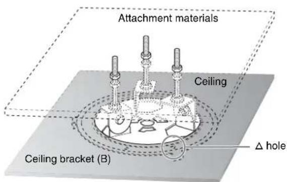
5 Attach the wire rope to the materials near the ceiling. Use an M5 (3/16 inch) hexagon socket head cap screw (not supplied). Attach the wire rope to an area independent of the area where the ceiling bracket is attached.
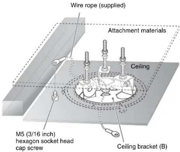
6 Attach the wire rope to the ceiling bracket (A). Pass the wire rope through the fixing hole and attach its end to the attachment hole on the bracket using the supplied one screw ( M4 × 8).
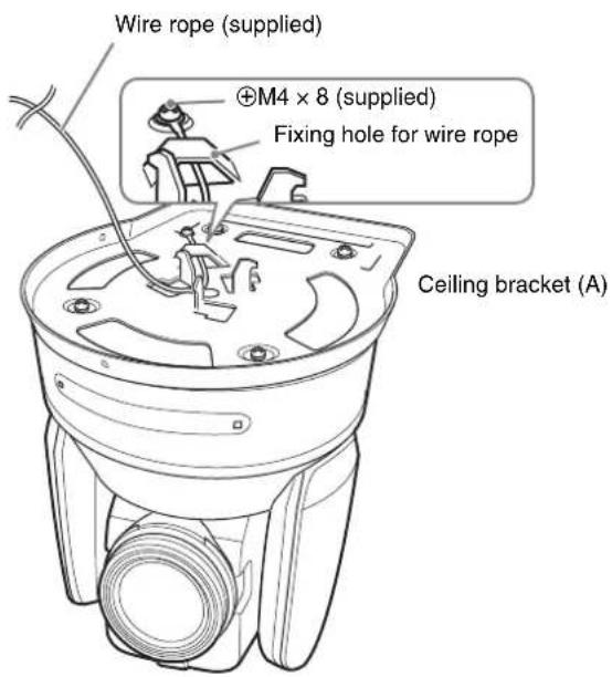
Caution
For attaching the wire rope to the bracket, use only the supplied screw. Using another screw may disable the function of the wire rope.
7 Insert the protrusions on the ceiling bracket (A) into the spaces prepared in the ceiling bracket (B) with the hole in the front of the ceiling bracket (A) aligned with the hole on the ceiling bracket (B), and temporarily attach them by turning the ceiling bracket (A) with the camera clockwise.
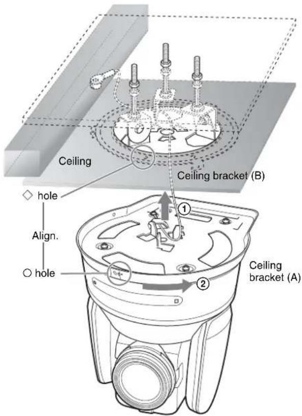
8 Secure the ceiling brackets (A) and (B) using the supplied three screws ( M3 × 8 ).
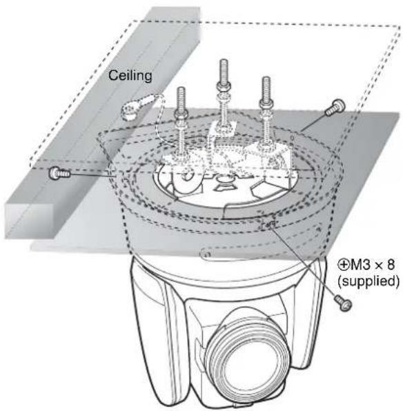
9 Connect the cables to the connectors on the rear of the camera.
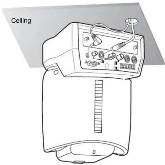
Notes
• Take the proper steps and make sure that the weight of the connected cables does not strain the connectors.
- For details about the supplied AC power cord and DC-cord secure connection attachment, see "Connections" on page 64.
10 The SONY and/or HD nameplates can be turned upside down, if necessary.
To remove the camera
1 Remove the three screws used to attach the camera in step 8 of "Installation on a ceiling (example)."
2 Turn the camera with the bracket counterclockwise to remove.
Installation on a shelf, etc., in a high position (example)
1 Remove the four screws on the bottom of the camera to remove the four feet.
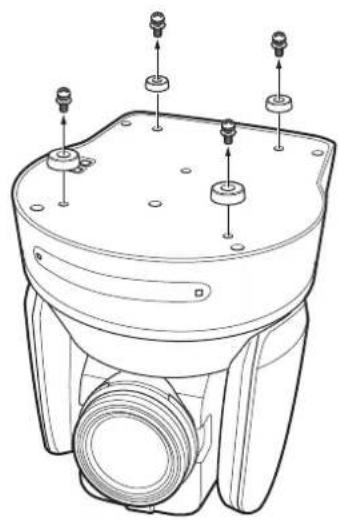
natural_image
Technical line drawing of a mechanical device with mounting holes and threaded components (no text or symbols)2 Attach the ceiling bracket (A) to the bottom of the camera using the supplied four screws ( M3 × 8 ). Position the O hole for screwing on the ceiling bracket (A) to the front of the camera as illustrated, align the screw holes on the ceiling bracket with those on the bottom of the camera, then attach the bracket to the camera.
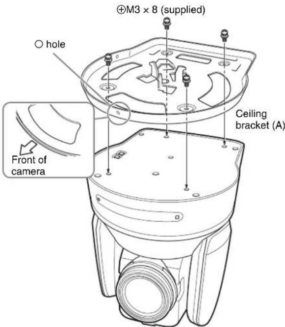
Note
For attaching the camera to the ceiling bracket, use only the supplied screws. Using other screws may damage the camera.
3 Attach the supplied wire rope to the ceiling bracket (A).
Pass the wire rope through the fixing hole and attach its end to the attachment hole on the bracket using the supplied one screw ( M4 × 8 ).
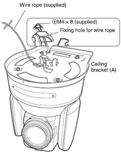
Caution
For attaching the wire rope to the bracket, use only the supplied screw. Using another screw may disable the function of the wire rope.
4 Attach the ceiling bracket (B) to a shelf, etc., on which the camera is to be installed. Use four screws (not supplied) appropriate for the materials of the shelf, etc. Align the hole on the ceiling bracket (B) in the direction where the front of the camera will be positioned later.
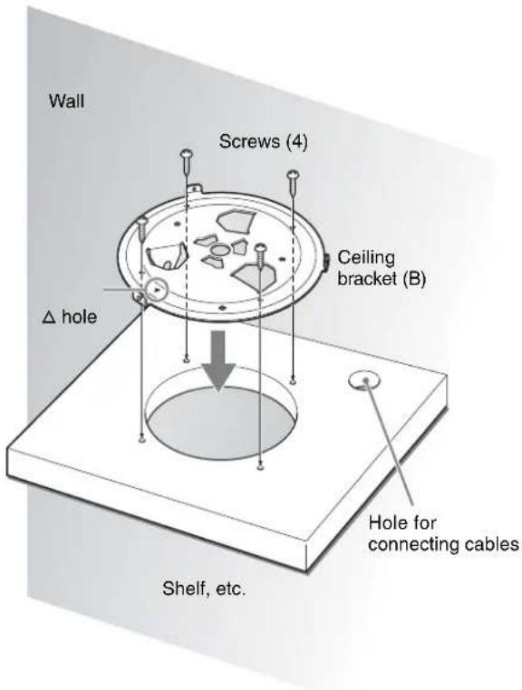
5 Attach the other end of the wire rope to the material near to where the camera is to be installed. Use an M5 (3/16 inch) hexagon socket head cap screw (not supplied). Attach the wire rope to the material independent of the surface where the ceiling bracket (B) is attached.
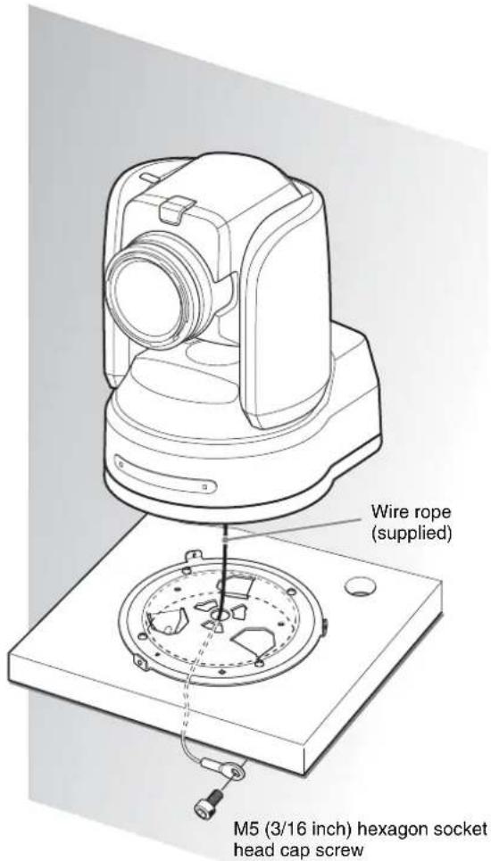
6 Insert the protrusions on the ceiling bracket (A) into the spaces prepared in the ceiling bracket (B) with the hole in the front of the ceiling bracket (A) aligned with the hole on the ceiling bracket (B), then temporarily attach them by turning the ceiling bracket (A) with the camera counterclockwise.
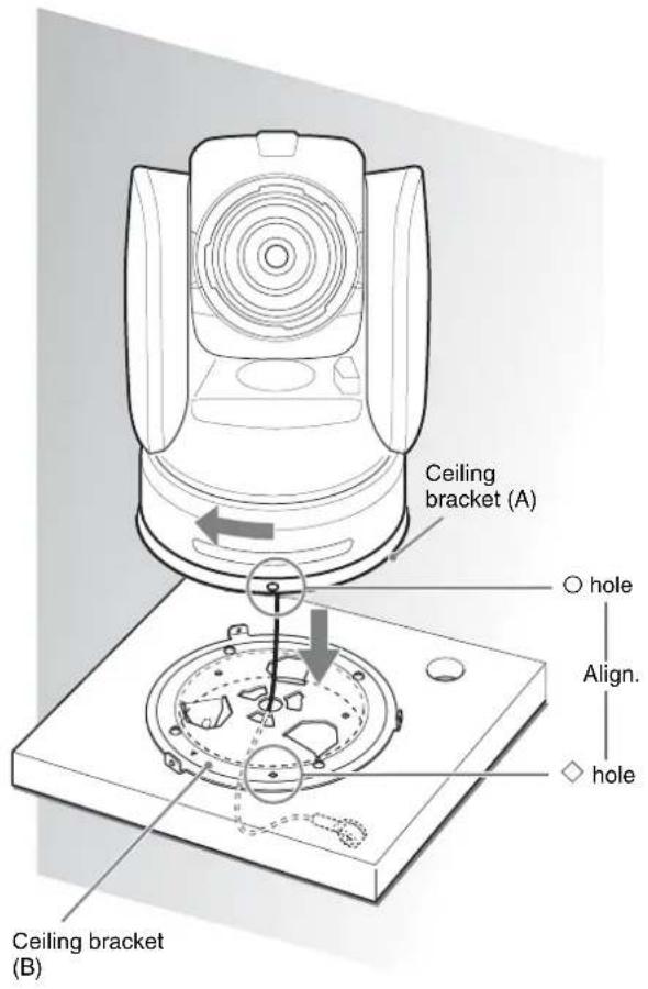
7 Secure the ceiling brackets (A) and (B) using the supplied three screws ( M3 × 8 ).
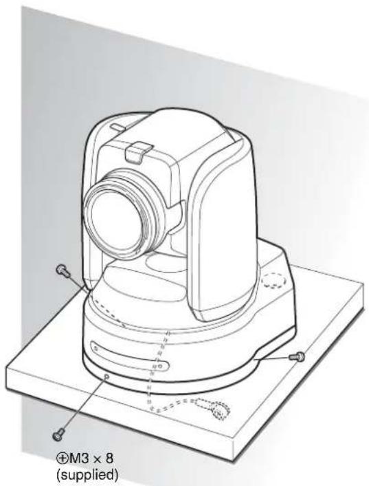
8 Connect the cables to the connectors on the rear of the camera.
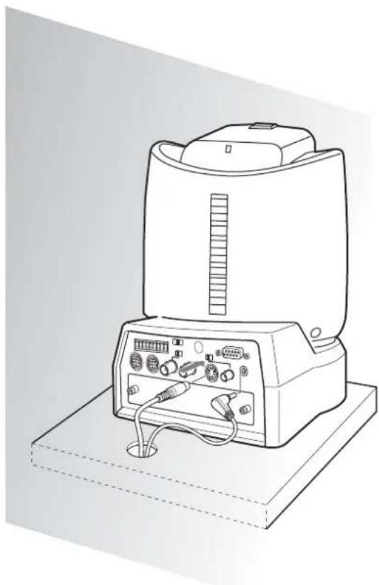
natural_image
Line drawing of a portable electronic device with control panel and ports (no text or symbols)Notes
• Take the proper steps and make sure that the weight of the connected cables does not strain the connectors.
- For details about the supplied AC power cord and DC-cord secure connection attachment, see "Connections" on page 64.
To remove the camera
1 Remove the three screws used to attach the camera in step 7 of "Installation on a shelf, etc., in a high position (example)."
2 Turn the camera with the bracket clockwise to remove.
Connections
Connecting to an AC Outlet
Use the supplied AC power adaptor and AC power cord to connect the camera to an AC outlet.
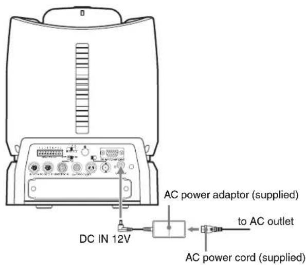
1 Remove the screw for fixing the DC-cord secure connection attachment from the rear panel of the camera.

2 Connect the supplied AC power adaptor and AC power cord.
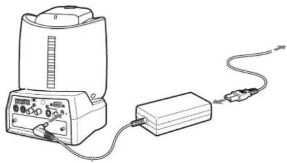
natural_image
Line drawing of a portable electronic device connected to a rectangular device via cable (no text or symbols)3 Attach the supplied DC-cord secure connection attachment and secure with the screw removed in Step 1 to prevent the AC power adaptor from being removed.
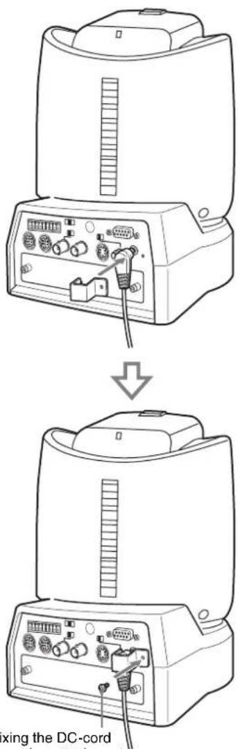
Screw for fixing the DC-cord secure connection attachment ( M3 × 6)
Note
Use the screw with the specified dimension to prevent internal damage to the camera.
Connecting the RM-BR300 Remote Control Unit
Use the RS-232C connecting cable supplied with the Remote Control Unit.
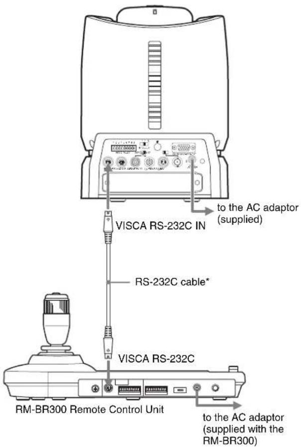
Note
When using the VISCA RS-232C connectors, check that the BOTTOM switch on the bottom of the camera (page 19) and the DIP switch on the bottom of the Remote Control Unit (page 24) are set to RS-232C.
To connect the Remote Control Unit using the VISCA RS-422 connectors
You can use the VISCA RS-422 connectors to connect the RM-BR300 Remote Control Unit to the camera instead of the VISCA RS-232C connectors. Use of the VISCA RS-422 connectors allows the connection up to 1,200 m (3,937 feet) away.
Prepare the connecting cable using the RS-422 connector plugs that come with the camera and the Remote Control Unit.
For making the cable, refer to the pin assignments of the VISCA RS-422 connector (pages 86 and 87) and the wiring diagram of VISCA RS-422 connection (page 89).
For the use of the RS-422 connector plugs, see page 90.

Notes
- When using the VISCA RS-422 connectors, check that the BOTTOM switch on the bottom of the camera (page 19) and the DIP switch on the bottom of the Remote Control Unit (page 24) are set to RS-422.
- When the connections using the VISCA RS-422 connectors are made, the VISCA RS-232C connection is not available.
- For the detailed wiring of the VISCA RS-422 connection, see the wiring diagram of VISCA RS-422 connection (page 89).
Connecting a Monitor, etc., Equipped with the Analog Component (YPbPr) Input Connector
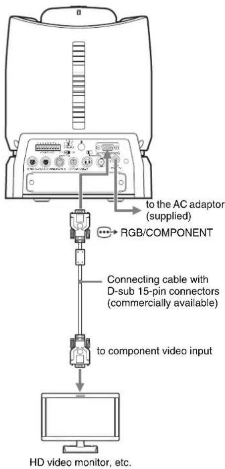
Connecting a Device Equipped with VISCA RS-232C Connector
Connections with the VISCA RS-232C cables (cross type) enable control of multiple cameras with a single RM-BR300 Remote Control Unit.
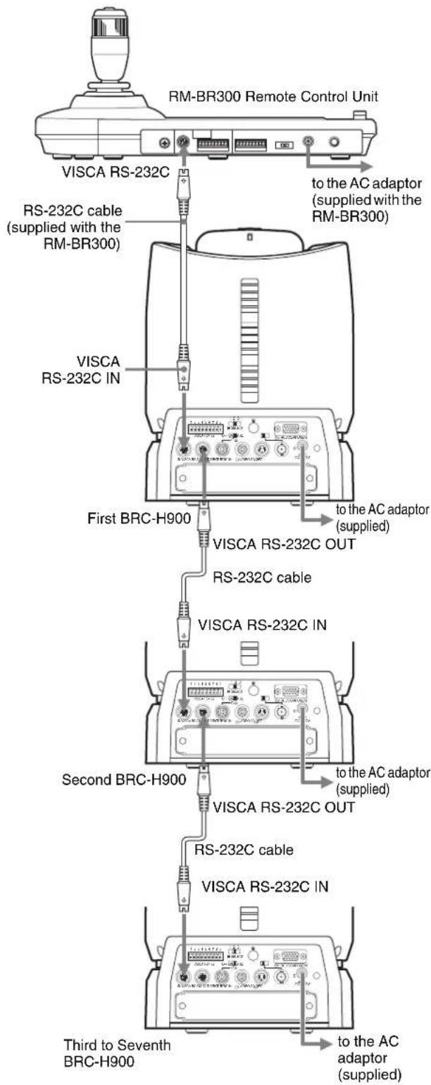
You can connect the camera to a computer equipped with the VISCA RS-232C connector instead of the connection to the RM-BR300 Remote Control Unit.
Note
When using the VISCA RS-232C connectors, check that the BOTTOM switch on the bottom of the camera (page 19) and the DIP switch on the bottom of the Remote Control Unit (page 24) are set to RS-232C.
Connecting a Device Equipped with VISCA RS-422 Connector
Connection via the VISCA RS-422 connectors enables control of multiple cameras. This allows the connection up to 1,200 m (3,937 feet) away.
Prepare the connecting cable using the RS-422 connector plugs that come with the camera and the Remote Control Unit.
For making the cable, refer to the pin assignments of the VISCA RS-422 connector (pages 86 and 87) and the wiring diagram of VISCA RS-422 connection (page 89).
For the use of the RS-422 connector plugs, see page 90.
Notes
- When using the VISCA RS-422 connectors, check that the BOTTOM switch on the bottom of the camera (page 19) and the DIP switch on the bottom of the Remote Control Unit (page 24) are set to RS-422.
- When the connections using the VISCA RS-422 connectors are made, the VISCA RS-232C connection is not available.
- Do not make the VISCA RS-422 connection and the VISCA RS-232C connection simultaneously. If both cables are connected simultaneously, the camera may malfunction.
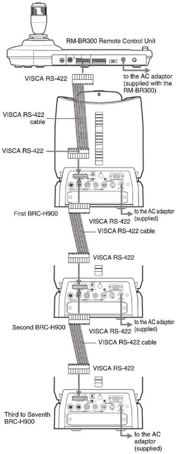
Connecting a Video Monitor Equipped with Composite Video or S Video Input Connector
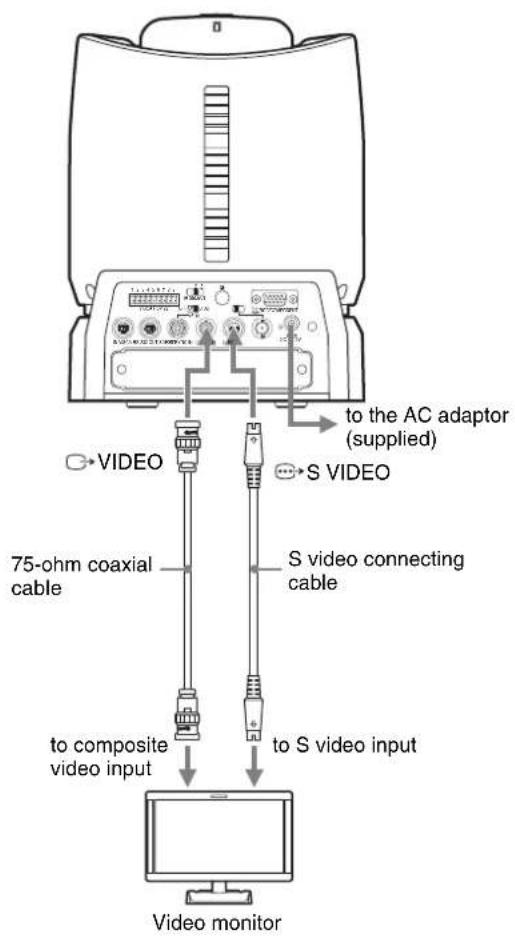
Connecting a Video Monitor, VTR, etc., Equipped with SDI Input Connector
Set the HD/SD select switch on the camera to SD, and turn on the camera. You can output the signal from the camera by converting it into an SDI signal that conforms to SMPTE 259M serial digital interface standards.
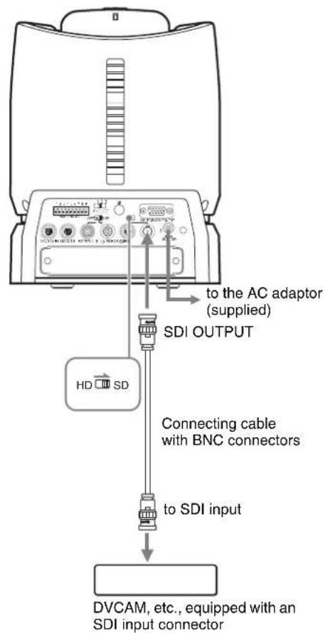
You can change an image size (aspect ratio) of the signals output from the SDI OUTPUT connector. For details, see "VIDEO OUT Menu" on page 42.
Connecting a VTR Equipped with HD-SDI Input Connectors
Set the HD/SD select switch on the camera to HD, and turn on the camera. You can output the signal from the camera by converting it into a signal compliant with HD-SDI standards (SMPTE 292 serial digital interface).

Connecting the BRU-SF10 HD Optical Multiplex Unit
When you install an optional BRBK-SF1 Optical Multiplex Card in the camera, you can connect the camera to the BRU-SF10 Optical Multiplex Unit using the CCFC-S200 Optical Fiber Cable. This allows you to control the camera from up to 2,000 m (6,562 feet) away.
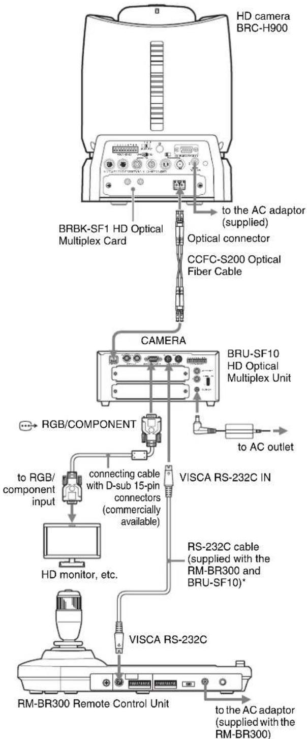
flowchart
graph TD
    A["HD camera BRC-H900"] --> B["BRBK-SF1 HD Optical Multiplex Card"]
    B --> C["to the AC adaptor (supplied)"]
    B --> D["Optical connector"]
    B --> E["CCFC-S200 Optical Fiber Cable"]
    C --> F["CAMERA"]
    D --> F
    E --> F
    F --> G["BRU-SF10 HD Optical Multiplex Unit"]
    G --> H["to AC outlet"]
    F --> I["RGB/COMPONENT"]
    I --> J["to RGB/ component input"]
    J --> K["connecting cable with D-sub 15-pin connectors (commercially available)"]
    K --> L["HD monitor, etc."]
    L --> M["RS-232C cable (supplied with the RM-BR300 and BRU-SF10)*"]
    M --> N["VISCA RS-232C"]
    N --> O["VISCA RS-232C"]
    O --> P["RM-BR300 Remote Control Unit"]
    P --> Q["to the AC adaptor (supplied with the RM-BR300)"]
* The VISCA RS-422 connection is also available if you use the VISCA RS-422 connectors.
Notes
- When the connection using the Optical Fiber Cable is made, the VISCA RS-232C and VISCA RS-422 connectors on the camera cannot be used.
- When using the VISCA RS-232C connectors or VISCA RS-422 connectors, check the VISCA FUNCTION switch on the rear of the Optical Multiplex Unit (page 26) and the DIP switch on the bottom of the Remote Control Unit (page 24) are set to RS-232C or RS-422 correctly.
Notes on use of the CCFC-S200 HD Optical Fiber Cable
- In order to prevent cable transmission loss, keep away bend in the cable more than 40 mm (1 5/8 inches) radius.
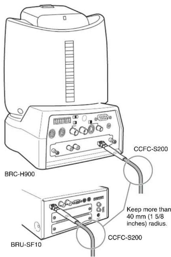
• To connect two Optical Fiber Cables, use the extension plug supplied with the cable.
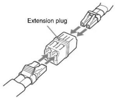
Connecting a Video Switcher
Use a commercially available video switcher to switch between the multiple camera signals to be output.
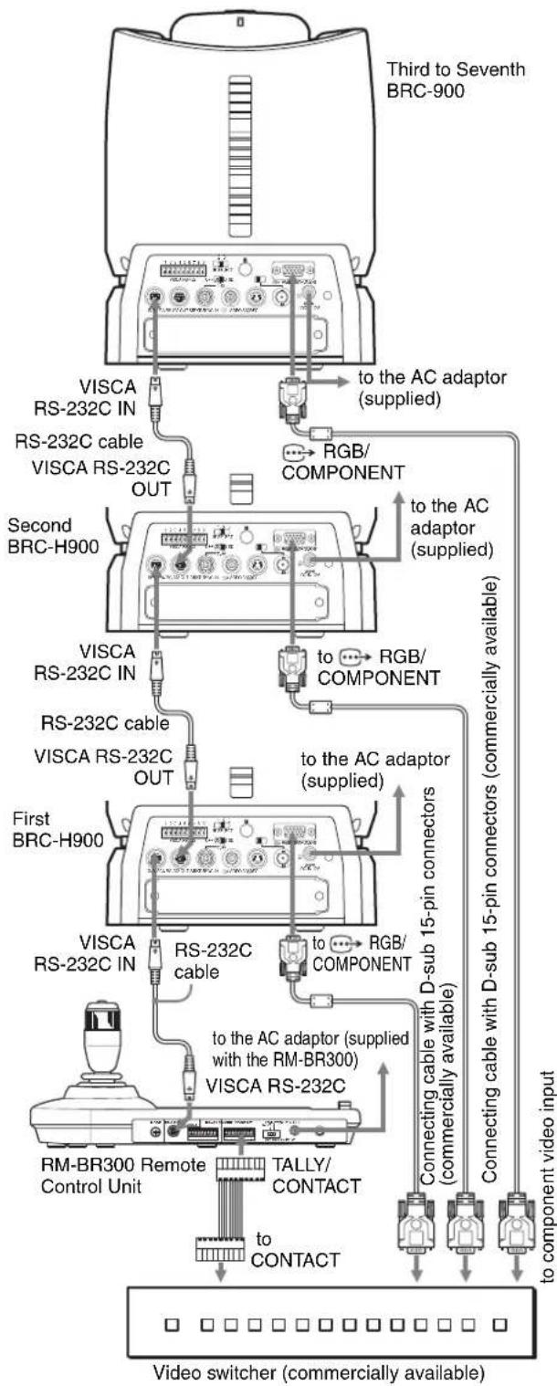
flowchart
graph TD
    A["Third to Seventh BRC-900"] -->|to the AC adaptor (supplied)| B["RS-232C IN"]
    A -->|to the AC adaptor (supplied)| C["RS-232C OUT"]
    A -->|to the AC adaptor (supplied)| D["RS-232C IN"]
    A -->|to the AC adaptor (supplied)| E["RS-232C OUT"]
    A -->|to the AC adaptor (supplied)| F["RS-232C IN"]
    A -->|to the AC adaptor (supplied)| G["RS-232C OUT"]
    A -->|to the AC adaptor (supplied)| H["RS-232C IN"]
    A -->|to the AC adaptor (supplied)| I["RS-232C OUT"]
    A -->|to the AC adaptor (supplied)| J["RS-232C IN"]
    A -->|to the AC adaptor (supplied)| K["RS-232C OUT"]
    A -->|to the AC adaptor (supplied)| L["RS-232C IN"]
    A -->|to the AC adaptor (supplied)| M["RS-232C OUT"]
    A -->|to the AC adaptor (supplied)| N["RS-232C IN"]
    A -->|to the AC adaptor (supplied)| O["RS-232C OUT"]
    A -->|to the AC adaptor (supplied)| P["RS-232C IN"]
    A -->|to the AC adaptor (supplied)| Q["RS-232C OUT"]
    A -->|to the AC adaptor (supplied)| R["RS-232C IN"]
    A -->|to the AC adaptor (supplied)| S["RS-232C OUT"]
    A -->|to the AC adaptor (supplied)| T["RS-232C IN"]
    A -->|to the AC adaptor (supplied)| U["RS-232C OUT"]
    A -->|to the AC adaptor (supplied)| V["RS-232C IN"]
    A -->|to the AC adaptor (supplied)| W["RS-232C OUT"]
    A -->|to the AC adaptor (supplied)| X["RS-232C IN"]
    A -->|to the AC adaptor (supplied)| Y["RS-232C OUT"]
    A -->|to the AC adaptor (supplied)| Z["RS-232C IN"]
    A -->|to the AC adaptor (supplied)| AA["RS-232C OUT"]
    A -->|to the AC adaptor (supplied)| AB["RS-232C IN"]
    A -->|to the AC adaptor (supplied)| AC["RS-232C OUT"]
    A -->|to the AC adaptor (supplied)| AD["RS-232C IN"]
    A -->|to the AC adaptor (supplied)| AE["RS-232C OUT"]
    A -->|to the AC adaptor (supplied)| AF["RS-232C IN"]
    A -->|to the AC adaptor (supplied)| AG["RS-232C OUT"]
    A -->|to the AC adaptor (supplied)| AH["RS-232C IN"]
    A -->|to the AC adaptor (supplied)| AI["RS-232C OUT"]
    A -->|to the AC adaptor (supplied)| AJ["RS-232C IN"]
    A -->|to the AC adaptor (supplied)| AK["RS-232C OUT"]
    A -->|to the AC adaptor (supplied)| AL["RS-232C IN"]
    A -->|to the AC adaptor (supplied)| AM["RS-232C OUT"]
    A -->|to the AC adaptor (supplied)| AN["RS-232C IN"]
    A -->|to the AC adaptor (supplied)| AO["RS-232C OUT"]
    A -->|to the AC adaptor (supplied)| AP["RS-232C IN"]
    A -->|to the AC adaptor (supplied)| AQ["RS-232C OUT"]
    A -->|to the AC adaptor (supplied)| AR["RS-232C IN"]
    A -->|to the AC adaptor (supplied)| AS["RS-232C OUT"]
    A -->|to the AC adaptor (supplied)| AT["RS-232C IN"]
    A -->|to the AC adaptor (supplied)| AU["RS-232C OUT"]
    A -->|to the AC adaptor (supplied)| AV["RS-232C IN"]
    A -->|to the AC adaptor (supplied)| AW["RS-232C OUT"]
    A -->|to the AC adaptor (supplied)| AX["RS-232C IN"]
    A -->|to the AC adaptor (supplied)| AY["RS-232C OUT"]
For connection with a video switcher, refer to the Operating Instructions of the switcher.
Connecting a Sync Signal Generator
To connect a single camera
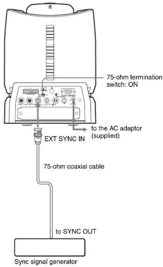
To connect multiple cameras to the HD sync signal generator
You can connect up to seven cameras.
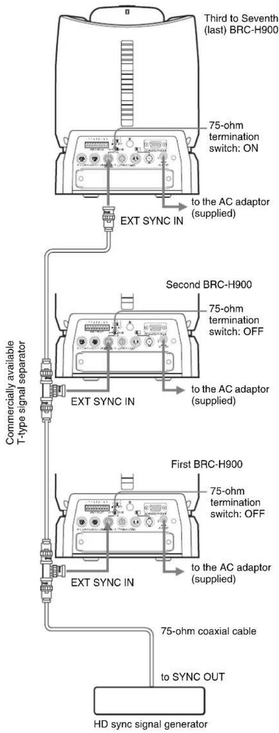
To connect multiple cameras to the SD sync signal generator
You can connect up to seven cameras.
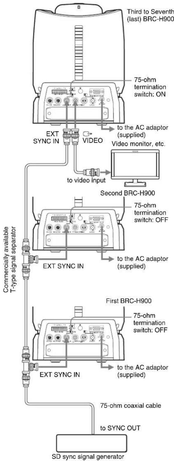
flowchart
graph TD
    A["Third to Seventh (last) BRC-H900"] --> B["75-ohm termination switch: ON"]
    B --> C["EXT SYNC IN"]
    C --> D["VIDEO"]
    D --> E["to video input"]
    E --> F["Second BRC-H900"]
    F --> G["75-ohm termination switch: OFF"]
    G --> H["EXT SYNC IN"]
    H --> I["to the AC adaptor (supplied)"]
    I --> J["First BRC-H900"]
    J --> K["75-ohm termination switch: OFF"]
    K --> L["EXT SYNC IN"]
    L --> M["to the AC adaptor (supplied)"]
    M --> N["75-ohm coaxial cable"]
    N --> O["SD sync signal generator"]
    style A fill:#f9f,stroke:#333
    style F fill:#ccf,stroke:#333
    style J fill:#ccf,stroke:#333
    style K fill:#ccf,stroke:#333
Appendix
List of Messages
The following messages may appear on the screen. Take the necessary measures shown below.
Indicators on the BRC-H900 camera
| Indicator Meaning/remedies | |
| STANDBY lamp flashes. | The camera stopped moving due to an error in the pan/tilt mechanism. Reset the pan/tilt position or turn off the power of the camera, then turn it on again. |
| The back tally lamp flashes. | Turn off the power of the camera, then consult your Sony dealer. |
Messages for the BRC-H900 camera
| Message Meaning/remedies | |
| Please restart system! | You are prompted to restart the power of the camera after you changed the setting of “IMG FLIP” in the SYSTEM menu. Use the POWER button on the supplied Remote Commander or the POWER button on the RM-BR300 Remote Control Unit to turn the power off, then on. The changed setting becomes effective. |
| PRESET xx OK (xx = preset position numbers 01 to 16) | When you store the camera settings into the memory (POSITION 1-16), the message will appear for two seconds. |
| One Push WB...OK (NG) | While the white balance is automatically adjusted, the message will appear. Wait for a while. When the adjustment is complete, it will disappear. |
| ⚠️ FAN STOP! (The message will flash in the main menu.) | Turn off the power of the camera, then consult your Sony dealer. |
| CAUTION COOLING FAN STOPPED! | Turn off the power of the camera, then consult your Sony dealer. |
| PRESET (xx) OUT OF RANGE (xx = preset position numbers 01 to 16) | This message appears when you preset the camera position when the pan/tilt position of the camera is out of range of the current PAN-TILT LIMIT setting. This camera position presetting will fail. Perform the presetting again after moving the camera within the range of the PAN-TILT LIMIT setting. |
Messages for video outputs from the BRU-SF10 HD Optical Multiplex Unit
| Message Meaning/remedies | |
| Communication errorPlease check connection | The AC adaptor is not properly connected to the DC IN 12V connector on the BRC-H900, or the AC cord may be disconnected from the power outlet. Check that the BRC-H900 is turned on.The CCFC-S200 Optical Fiber Cable connecting the BRC-H900 to the BRU-SF10 is connected improperly, or the optical fiber cable may be damaged.Image frequency settings for the BRC-H900 and the BRU-SF10 may be different. For details on settings, see page 20 and 26. After checking the above conditions, restart the BRC-H900 and BRU-SF10. |
| Option card errorPlease check option card | This message appears when an unsupported optional interface card is inserted in the card slot of the BRU-SF10. Remove the card after turning off the BRU-SF10. |
Troubleshooting
Before bringing in your camera for service, check the following guide to troubleshoot the problem. If the problem cannot be corrected, consult your Sony dealer.
| Symptom Cause Remedy | ||
| The power of the camera is not turned on. | The supplied AC power adaptor is not connected to the DC IN 12V jack firmly. | Insert the power cord firmly as far as it will go. |
| The AC power cord is not inserted firmly into the AC power adaptor or the AC outlet. | Insert the power cord firmly as far as it will go. | |
| The BRBK-SF1 HD Optical Multiplex Card is inserted into the card slot. | Remove the card from the card slot. | |
| When using the far-distance remote control system with the BRBK-SF1 HD Optical Multiplex Card, CCFC-S200 Optical Fiber Cable and BRU-SF10 HD Optical Multiplex Unit, the Optical Fiber Cable is not properly connected or the HD Optical Multiplex Unit is not turned on. | Connect the optical fiber cable correctly. | |
| Turn on the HD Optical Multiplex Unit, or plug in the power cord of the unit to an AC outlet firmly. | ||
| The camera cannot be turned on with the supplied Remote Commander. | IR RECEIVE in the SYSTEM menu is set to OFF. | Use the RM-BR300 Remote Control Unit to open the menu and set IR RECEIVE to ON. (page 40) |
| The camera is connected to a BRU-SF10 HD Optical Multiplex Unit. | The camera cannot be turned on/off using the supplied Remote Commander. Instead, use the power switch on the BRU-SF10 or the POWER button on an RM-BR300 connected to the BRU-SF10 to turn on/off the camera. | |
| The picture is not displayed on the video monitor connected to the camera. | The video cable is not connected properly. Check the connection between the camera and video monitor. | |
| The exposure is not set correctly on the camera. | Set the exposure correctly in the EXPOSURE menu. | |
| Pan, tilt or zoom cannot be operated. A menu is displayed on the monitor screen. Press the DATA SCREEN button on the supplied Remote Commander or the MENU button on the RM-BR300 Remote Control Unit to turn off the menu from the monitor screen. | ||
| The Remote Commander does not work. The CAMERA SELECT button you pressed on the Remote Commander does not match the number set with the IR SELECT switch on the camera. | Press the CAMERA SELECT button corresponding to the IR SELECT switch setting on the camera (page 46). | |
| The camera cannot be operated with the RM-BR300 Remote Control Unit. | The connection using the VISCA RS-422 connectors is not correctly made. | Check that the connection to the VISCA RS-422 connectors is correctly made, and the RS-422 cable is properly connected. |
| The BOTTOM switch on the bottom of the camera is set to any other address than “0 (AUTO).” | Identify the address of the camera, then select the same address by the CAMERA button of the Remote Control Unit. | |
| VISCA control setting is not correct. Select the proper setting (RS-232C or RS-422) with the BOTTOM switch on the bottom of the camera (page 19) and the DIP switch on the Remote Control Unit (page 24). | ||
| The communication baud rate setting of the camera and the RM-BR300 differ. | Select the same communication baud rate (9,600 bps or 38,400 bps) with the BOTTOM switch on the bottom of the camera (page 19) and the DIP switch on the Remote Control Unit (page 24). | |
| The VISCA control is not available with a computer connected to the camera. | The computer is not correctly connected to the camera. | Make sure the connection between the computer and camera is made correctly. |
| Check that the VISCA control setting (RS-232C or RS-422) and the baud rate setting (9,600 bps or 38,400 bps) are properly made with the BOTTOM switch on the bottom of the camera (page 19) and the DIP switch on the Remote Control Unit (page 24). | ||
| Try to connect the camera to the RM-BR300 Remote Control Unit to check that the camera works properly. | ||
| The picture quality obtained from the camera connected to a computer differs from that from the camera connected to a video monitor. | Depending on your computer or video capture board, you may not be able to obtain the expected picture quality. | Consult your computer manufacturer or dealer for details. |
| The camera cannot be operated at all. | — | Pull out the plug of the power cord from the AC outlet, then reinsert it into the AC outlet after a while. |

Menu Configuration
The menus of the camera are configured as described below.
For more information, refer to the pages indicated in parentheses.
The initial settings of each item are in bold.
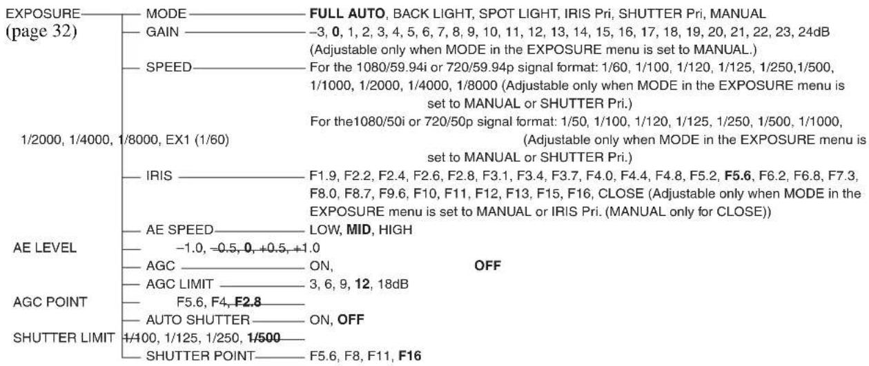
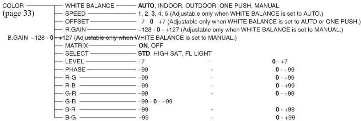
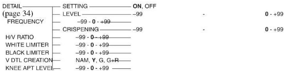

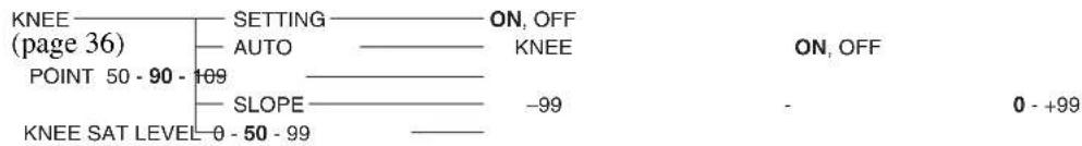

flowchart
graph TD
    A["GAMMA"] --> B["SELECT"]
    B --> C["LEVEL"]
    C --> D["BLACK GAMMA"]
    D --> E["BLACK"]
    E --> F["AUTO BLACK BALANCE"]
    F --> G["R.BLACK"]
    F --> H["B.BLACK"]
    B --> I["STD1, STD2, STD3, STD4, CINE1, CINE2, CINE3, CINE4"]
    C --> J["-99~0~+99"]
    D --> K["-99~0~+99"]
    E --> L["-99~0~+99"]
    F --> M["ON, OFF"]
    G --> N["-99~0~+99"]
    H --> O["-99~0~+99"]
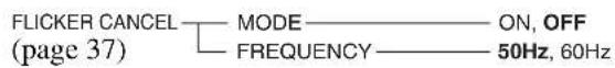

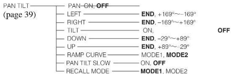
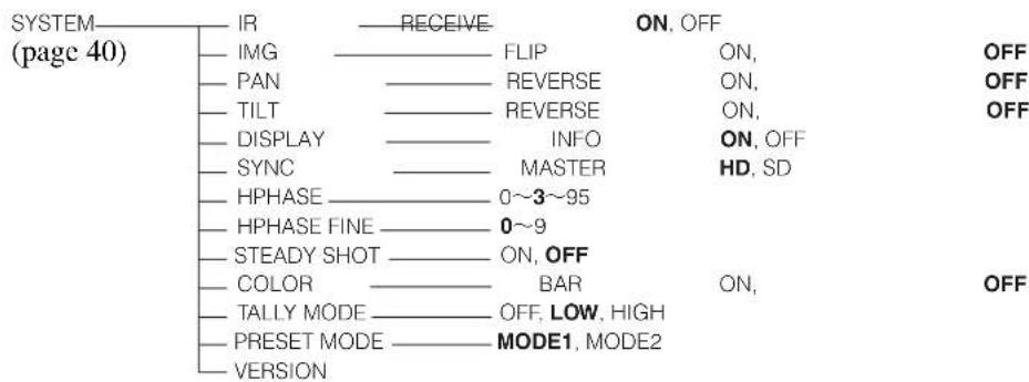
![VIDEO OUT (page 42) FORMAT RGB, YPbPr ADD SYNC SYNC TYPE VD, 1^SYNC IMG SIZE 16:9 [LETTER], 4:3 [CROP], 4:3 [SQUEEZE] SET 1) OR, OFF RGB, OFF](/content/2026/03/486734/images/2b81d7252048ace3628cded390d2c9c41b719cac0206d3826c205a1356d1a2f0.jpg)
^1) Does not appear when an HD output signal is 1080/50i or 720/50p format.
Menus when an Interface Card is inserted
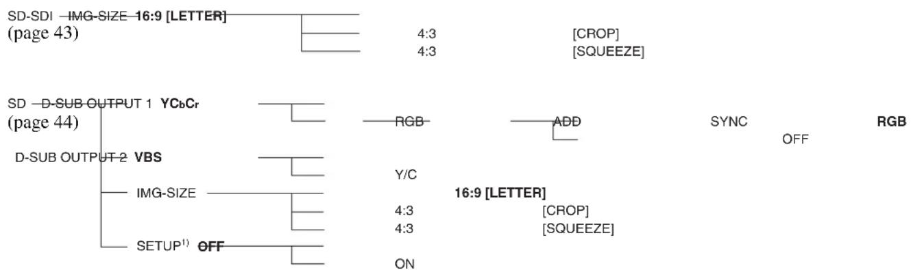
flowchart
graph TD
    A["SD-SDI -IMG-SIZE 16:9 [LETTER"] (page 43)] --> B["4:3"]
    B --> C["CROP"]
    B --> D["SQUEEZE"]
    E["SD -D-SUB-OUTPUT 1 YCbCr (page 44)"] --> F["RGB"]
    F --> G["ADD"]
    G --> H["SYNC"]
    I["D-SUB OUTPUT 2 VBS"] --> J["Y/C"]
    J --> K["16:9 [LETTER"]]
    L["IMG-SIZE"] --> M["4:3"]
    L --> N["4:3"]
    O["SETUP¹"] --> P["ON"]
    Q["OFF"] --> R["ON"]
^1) Does not appear when an HD output signal is 1080/50i or 720/50p format.
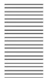
Presetting Items
The following setting items can be stored in the memory of the camera.
General presetting items
| Presetting item Presetting position number | |
| Pan/tilt position ● ○ | |
| ZOOM position ● ○ | |
| FOCUS position (only when MODE in the EXPOSURE menu set to MANUAL) | ● ○ |
Presetting menu items ^4)
| Presetting item Presetting position number | ||
| EXPOSURE MODE ● | ○ | |
| AE SPEED □ | ||
| AE LEVEL □ | ||
| AGC □ | ||
| AGC LIMIT □ | ||
| AGC POINT □ | ||
| AUTO SHUTTER □ | ||
| SHUTTER LIMIT □ | ||
| SHUTTER POINT □ | ||
| GAIN(only when MODE in the EXPOSURE menu set to MANUAL) | ● | ○ |
| SHUTTER(only when MODE in the EXPOSURE menu set to MANUAL) | ● | ○ |
| IRIS(only when MODE in the EXPOSURE menu set to MANUAL) | ● | ○ |
| SHUTTER(only when MODE in the EXPOSURE menu set to SHUTTER Pri) | ● | ○ |
| IRIS(only when MODE in the EXPOSURE menu set to IRIS Pri) | ● | ○ |
| WHITE BALANCE MODE ● | ○ | |
| SPEED | □ | |
| OFFSET | ● | ○ |
| MATRIX | □ | |
| Presetting item Presetting position number | ||
| SELECT | ||
| LEVEL (MATRIX) | ||
| PHASE | ||
| R-G | ||
| R-B | ||
| G-R | ||
| G-B | ||
| B-R | ||
| B-G | ||
| R.GAIN (only when MODE in the EXPOSURE menu set to MANUAL) | ||
| B.GAIN (only when MODE in the EXPOSURE menu set to MANUAL) | ||
| DETAIL SETTING | ||
| LEVEL (DETAIL) | ||
| FREQUENCY | ||
| CRISPENING | ||
| H/V RATIO | ||
| WHITE LIMITER | ||
| BLACK LIMITER | ||
| V DTL CREATION | ||
| KNEE APT LEVEL | ||
| COLOR DETAIL SETTING | ||
| LEVEL (COLOR DETAIL) | ||
| AREA INDICATION | _1) | |
| SATURATION | ||
| PHASE | ||
| WIDTH | ||
| KNEE SETTING | ||
| AUTO KNEE | ||
| POINT | ||
| SLOPE | ||
| KNEE SAT LEVEL | ||
| GAMMA SELECT | ||
| LEVEL (GAMMA) | ||
| BLACK | ||
| BLACK GAMMA | ||
| FLICKER CANCEL MODE | ||
| FREQUENCY | ||
| FOCUS MODE | ||
| PAN LIMIT | - | |
| LEFT | - | |
| RIGHT | - | |
| TILT LIMIT | - | |

| Presetting item | Presetting position number | |
| 1 | 2 - 16 | |
| DOWN - | ||
| UP - | ||
| RAMP CURVE - | ||
| IR RECEIVE - | ||
| IMG FLIP ^2) | - | |
| PAN REVERSE - | ||
| TILT REVERSE | - | |
| DISPLAY INFO | - | |
| SYNC MASTER | - | |
| HPHASE | - | |
| HPHASE FINE - | ||
| STEADY SHOT | - | |
| COLOR BAR | _-^1) | |
| TALLY MODE | - | |
| FORMAT (HD OUTPUT) | - | |
| ADD SYNC | - | |
| SYNC TYPE | - | |
| IMG SIZE (SD OUTPUT) | - | |
| SETUP ^3) (SD OUTPUT) | - | |
^1) The item is set to OFF automatically when the power is turned off and on again even if the item is set to ON while you preset.
^2) The current setting of IMG FLIP is recalled regardless of presetting operations.
^3) The item cannot be stored for 1080/50i or 720/50p output signal.
^4) When the PRESET MODE2 is selected, the items cannot be stored in the preset positions between 2 to 16.
Presetting menu items while the Interface Card is inserted into BRU-SF10 connected with the camera
| Presetting item | Presetting position number | |
| 1 | 2 – 16 | |
| Menu items displayed only when the HFBK-SA1 is installed | ||
| DSUB OUTPUT 1 | - | |
| ADD SYNC | - | |
| DSUB OUTPUT 2 | - | |
| IMG SIZE ^1) | - | |
| SETUP (not available for 50i output signal) | - | |
| Menu items displayed only when the HFBK-HSD2 is installed | ||
| IMG SIZE ^1) | - | |
^1) When installed in the BRC-H900 and in use, the IMG SIZE setting is linked with the VIDEO OUT setting. When two BRBK-SA1 cards are installed in the BRU-SF10, or when a BRBK-SA1 and BRBK-HSD2 are used as SD-SDI, the IMG SIZE settings for both option cards are linked. When two BRBK-HSD2 cards are installed in the BRU-SF10, or when a BRBK-SA1 and BRBK-HSD2 are used as SD-SDI, the IMG SIZE settings for both option cards are linked.
●: Setting items are stored in memory. When the power is turned on, the camera starts with these settings.
○: Setting items are stored in memory. Recall the settings by selecting the preset number.
☐: Setting items are stored in memory. Because only one memory is available for this item, the last preset setting is stored regardless of the preset number, and recalled when the power is turned on. This setting cannot be reset. When the item setting is changed, the new setting is applied, even if the preset is recalled.
△: Setting items are stored in memory. When the power is turned on, the camera starts with these settings. This setting cannot be reset by pressing the RESET button. When the item setting is changed, the new setting is applied, even if the preset is recalled.
- : Setting items are not stored.
Specifications
System
Video signal 1080/59.94i, 1080/50i, 720/59.94p, 720/50p (switched with the BOTTOM switch)
Synchronization
Internal/external synchronization, automatically switched
Image device 1/2 type (8.0 mm), 3CMOS pickup element
Total picture elements: Approx. 3,010,000 pixels
Effective picture elements: Approx. 2,070,000 pixels
Lens 14× (optical)
Filter diameter: 77 mm (Wide/tele conversion lens cannot be attached.) f = 5.8 to 81.2 mm, F1.9 to F16 f = 31.4 to 439 mm (equivalent to the focal length of a 35-mm camera)
Minimum object distance
800 mm (31 ^1 /2 inches)
Minimum illumination
4 lux (F1.9) with 50 IRE (WIDE end)
Shutter speed 1/60 (1/50 for 1080/50i or 720/50p format) to 1/8,000 sec.
Video S/N 50 dB (Typical) (component Y signal output)
Pan/tilt action Horizontal: ±170 degrees
Maximum panning speed: 60 degrees/sec. Minimum panning speed: 0.22 degrees/sec.
Vertical: +90 degrees, -30 degrees Maximum tilting speed: 60 degrees/sec. Minimum tilting speed: 0.22 degrees/sec.
Input/output connectors
Video output RGB/COMPONENT (D-sub 15-pin)
RGB: 0.7 Vp-p (no sync, at 75-ohm termination)
1 Vp-p ( ± 0.3 V, tri-level sync, at 75-ohm termination)
Component:
Y: 1 Vp-p ( ± 0.3 V, tri-level sync, at 75-ohm termination)
Pb/Pr: ±350 mVp-p, 75-ohm terminated
HD/VD Sync: 1 Vp-p, 75-ohm terminated
Tri-level Sync: ±300 mVp-p, 75-ohm terminated
VIDEO (BNC type)
Composite: 1 Vp-p (sync negative, at 75-ohm termination)
S VIDEO (mini DIN 4-pin)
S video output:
Y: 1 Vp-p (sync negative, at 75-ohm termination)
C: Same as chroma level of composite signal (at 75-ohm termination)
SDI OUT (BNC type, HD/SD switchable) Conforms to SMPTE 292/259M
External sync input
EXT SYNC IN: BNC type
Control input/output
VISCA RS-232C IN: Mini DIN 8-pin type
VISCA RS-232C OUT: Mini DIN 8-pin type
VISCA RS-422: 9-pin type
Control signal format
9600 bps/38400 bps
Data: 8 bit
Stop bit: 1
Power connector
JEITA type4 (DC IN 12V)
General
Input voltage 12 V DC (10.8 V to 13.2 V DC)
Current consumption
2.4 A max. (at 12 V DC), 28.8 W without optional Interface Card
Operating temperature
0^ to 40^ (32°F to 104°F)
Storage temperature
-20^ to +60^ (-4^ to +140^)
Dimensions Video camera: 198 mm × 260 mm ×
238 mm ( 7^7/8 in × 10^1/4 in × 9^3/_8 in) (w/h/d) (excluding protruding parts)
Remote Commander: 56 mm × 26 mm
× 210 ~mm (2^1/4 in × 1^1/16 in × 8^3/_8 in) (w/h/d)
Mass Video camera: Approx. 5.0 kg (11 lb 0.37 oz)
Remote Commander: 110 g (3.9 oz)
Installation angle
Less than ±15 degrees to the horizontal surface
Supplied accessories
AC power adaptor (100 to 240 V AC, 50/60 Hz) (1)
AC power cord (1)
Remote Commander (1)
Ceiling bracket (A) (1)
Ceiling bracket (B) (1)
Wire rope (1)
Screws (⊕M3 × 8) (7)
Screw (⊕M4 × 8) (1)
RS-422 connector plug (1)
DC-cord secure connection attachment (1)
Operating Instructions (1)
Operation Guide for Optional IP Control (1)
Design and specifications are subject to change without notice.
Notes
• Always verify that the unit is operating properly before use. SONY WILL NOT BE LIABLE FOR DAMAGES OF ANY KIND INCLUDING, BUT NOT LIMITED TO, COMPENSATION OR REIMBURSEMENT ON ACCOUNT OF THE LOSS OF PRESENT OR PROSPECTIVE PROFITS DUE TO FAILURE OF THIS UNIT, EITHER DURING THE WARRANTY PERIOD OR AFTER EXPIRATION OF THE WARRANTY, OR FOR ANY OTHER REASON WHATSOEVER.
- SONY WILL NOT BE LIABLE FOR CLAIMS OF ANY KIND MADE BY USERS OF THIS UNIT OR MADE BY THIRD PARTIES.
- SONY WILL NOT BE LIABLE FOR THE TERMINATION OR DISCONTINUATION OF ANY SERVICES RELATED TO THIS UNIT THAT MAY RESULT DUE TO CIRCUMSTANCES OF ANY KIND.
If the unit is suddenly taken from a cold to a warm location, or if ambient temperature suddenly rises, moisture may form on the outer surface of the unit and/or inside of the unit. This is known as condensation. If condensation occurs, turn off the unit and wait until the condensation clears before operating the unit. Operating the unit while condensation is present may damage the unit.
The life expectancy of the AC adapter and the electrolytic capacitor is about 5 years under normal operating temperatures and normal usage (8 hours per day; 25 days per month). If usage exceeds the above normal usage frequency, the life expectancy may be reduced correspondingly.
Dimensions
BRC-H900 Video Camera
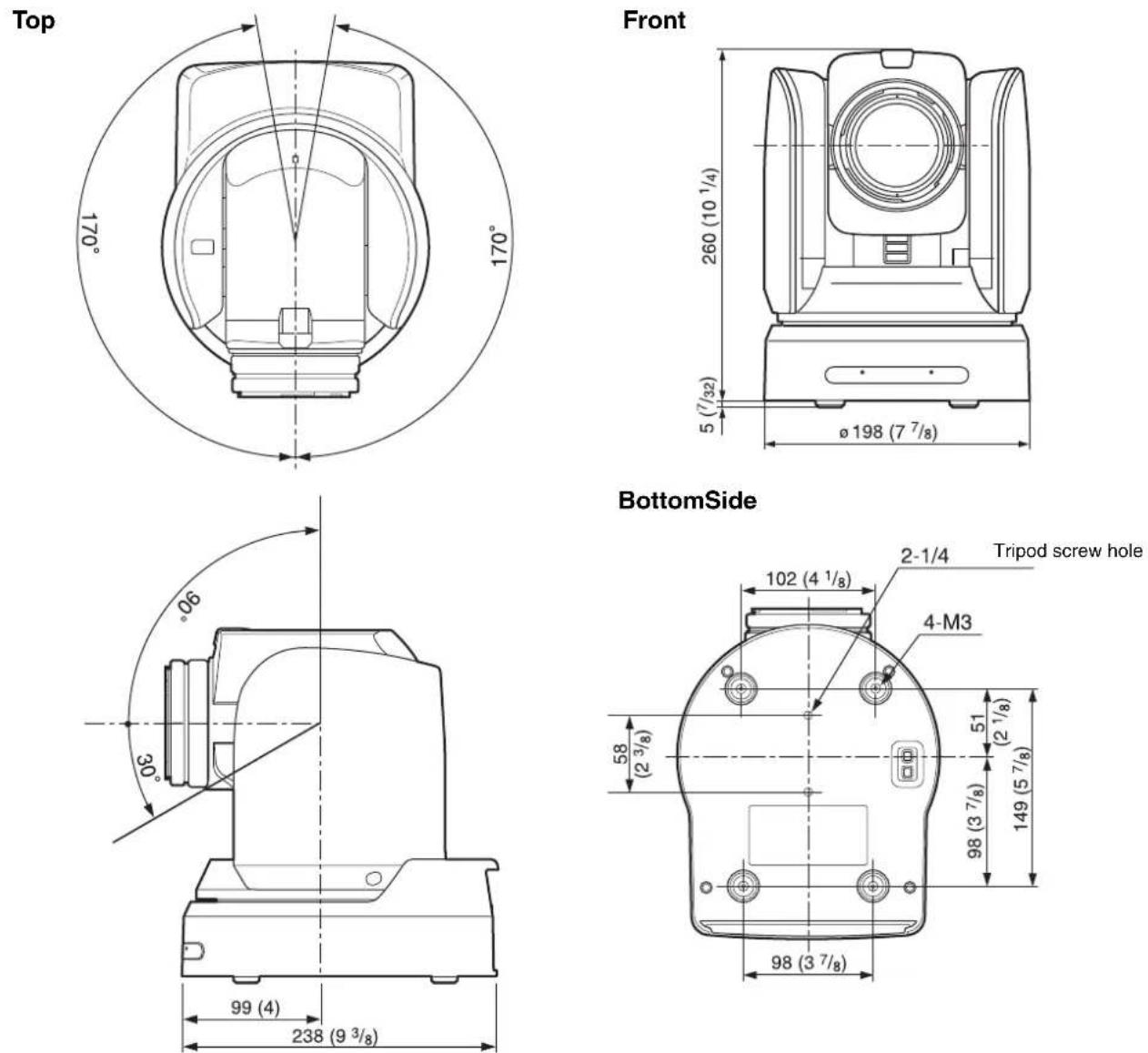
Ceiling Bracket (B)
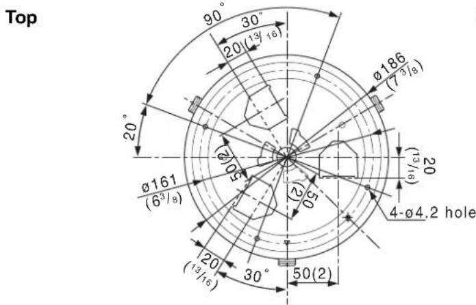
Side
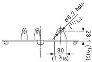
Unit: mm (inches)
RM-BR300 Remote Control Unit
Top
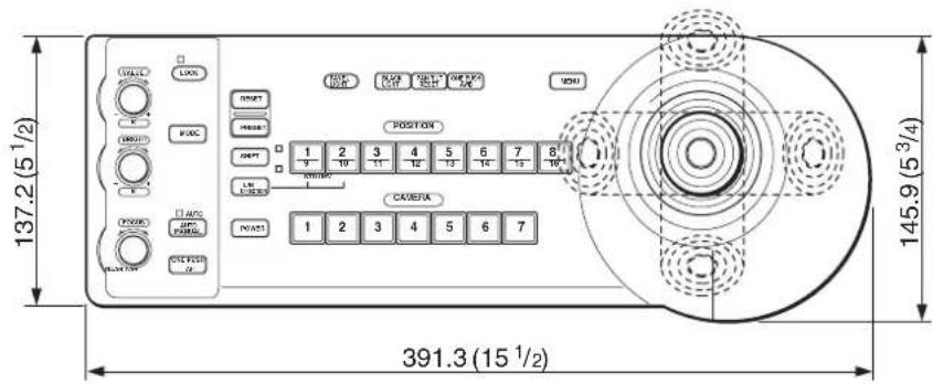
Side
Front
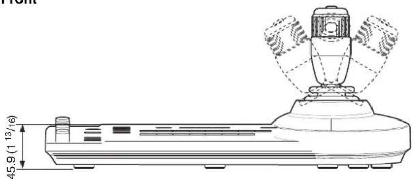

Bottom
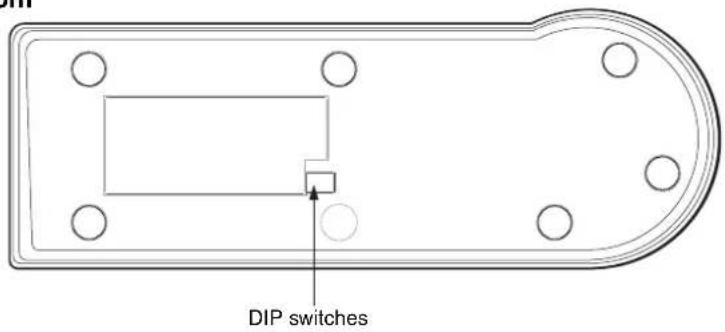
Unit: mm (inches)
Appendix
BRU-SF10 HD Optical Multiplex Unit
Top
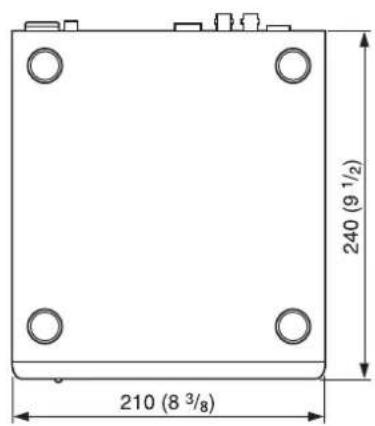
Side
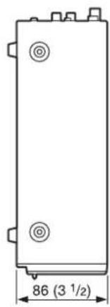
natural_image
Technical drawing of a rectangular electronic component with mounting holes and a dimension label (no text or symbols beyond measurement)Front
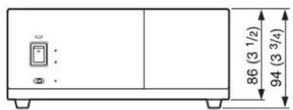
Unit: mm (inches)

Appendix
Pin Assignments
BRC-H900 Video Camera
VISCA RS-422 connector (connector plug 9-pin)
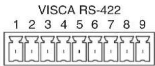
| Pin No. Function |
| 1 RXD OUT - |
| 2 RXD OUT+ |
| 3 TXD OUT - |
| 4 TXD OUT+ |
| 5 GND |
| 6 RXD IN - |
| 7 RXD IN+ |
| 8 TXD IN - |
| 9 TXD IN+ |
VISCA RS-232C IN connector (mini-DIN 8-pin, female)
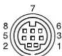
IN VISCA RS-232
| Pin No. Function | ||
| 1 | D | T |
| 2 | D | S |
| 3 TXD IN | ||
| 4 GND | ||
| 5 RXD IN | ||
| 6 GND | ||
| 7 SIRCS OUT * | ||
| 8 No Connection | ||
* The SIRCS OUT function is selectable with the BOTTOM switch on the bottom of the camera.
VISCA RS-232C OUT connector (mini DIN 8-pin, female)
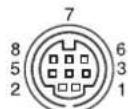
VISCA RS-232 OUT
| Pin No. Function | ||
| 1 | D | T |
| 2 DSR OUT | ||
| 3 TXD OUT | ||
| 4 GND | ||
| 5 RXD OUT | ||
| 6 GND | ||
| 7 No Connection | ||
| 8 No Connection | ||
Analog RGB/COMPONENT (D-sub 15-pin)
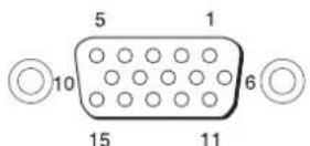
RGB/COMPONENT
| Pin No. | Function | |||
| At YPbPr COMPONENT setting | At YPbPr COMPONENT setting (at VD) | At RGB setting (at 1 ^1 SYNC) | At RGB setting (at VD) | |
| 1 Pr-OUT Pr-OUT R-OUT R-OUT | ||||
| 2 Y-OUT Y-OUT G-OUT G-OUT | ||||
| 3 Pb-OUT Pb-OUT B-OUT B-OUT | N | |||
| 4 GND GND I GND GND | ||||
| 5 GND GND GND GND | ||||
| 6 GND GND GND GND | ||||
| 7 GND GND GND GND | ||||
| 8 GND GND GND GND | ||||
| 9 | NC | NC | NC | NC |
| 10 | GND | GND | GND | GND |
| 11 | GND | GND | GND | GND |
| 12 | NC | NC | NC | NC |
| 13 | HD-OUT HD-OUT HD-OUT HD-OUT | |||
| 14 | Tri-level SYNC-OUT | Bi-level VD-OUT | Tri-level SYNC-OUT | Bi-level VD-OUT |
| 15 | NC | NC | NC | NC |
RM-BR300 Remote Control Unit (optional)
VISCA RS-232C output connector (mini DIN 8-pin, female)
RS-232C
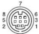
| Pin No. Function | ||
| 1 No Connection | ||
| 2 No Connection | ||
| 3 | T | X |
| 4 GND | ||
| 5 RXD IN | ||
| 6 GND | ||
| 7 No Connection | ||
| 8 No Connection | ||
VISCA RS-422 connector (connector plug, 9-pin)
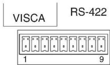
| Pin No. Function | ||
| 1 No Connection | ||
| 2 No Connection | ||
| 3 No Connection | ||
| 4 No Connection | ||
| 5 GND | ||
| 6 RXD IN – | ||
| 7 RXD IN+ | ||
| 8 | T | X |
| 9 | T | X |
TALLY/CONTACT connector (connector plug, 9-pin)
TALLY/CONTACT
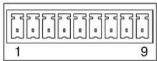
VISCA RS-232C IN connector (mini DIN 8-pin, female)
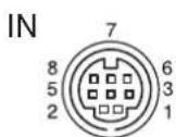
VISCA RS232C
| Pin No. Function | ||
| 1 | D | T |
| 2 | D | S |
| 3 TXD IN | ||
| 4 GND | ||
| 5 RXD IN | ||
| 6 GND | ||
| 7 No Connection | ||
| 8No Connection | I | N |
| D | I | N |
VISCA RS-232C OUT connector (mini DIN 8-pin, female)
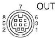
VISCA RS232C
| Pin No. Function |
| 1 DTR OUT |
| 2 DSR OUT |
| 3 TXD OUT |
| 4 GND |
| 5 RXD OUT |
| 6 GND |
| 7 No Connection |
| 8 No Connection |
VISCA RS-422 connector (connector plug, 9-pin)
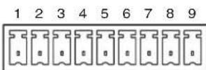
VISCA RS422
| Pin No. Function |
| 1 RXD OUT - |
| 2 RXD OUT+ |
| 3 TXD OUT - |
| 4 TXD OUT+ |
| 5 GND |
| 6 RXD IN - |
| 7 RXD IN+ |
| 8 TXD IN - |
| 9 TXD IN+ |
Analog RGB/COMPONENT (D-sub 15-pin)
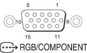
| Pin No. | Function | |||
| At YPbPr COMPONENT setting | At YPbPr COMPONENT setting (at VD) | At RGB setting (at SYNC) | At RGB setting (at VD) | |
| 1 Pr-OUT Pr-OUT R-OUT R-OUT | ||||
| 2 Y-OUT Y-OUT G-OUT G-OUT | ||||
| 3 Pb-OUT Pb-OUT B-OUT B-OUT | ||||
| 4 GND GND GND GND | ||||
| 5 GND GND GND GND | ||||
| 6 GND GND GND GND | ||||
| 7 GND GND GND GND | ||||
| 8 GND GND GND GND | ||||
| 9 N C | N C | N C | N C | N C |
| 10 GND GND GND GND | ||||
| 11 GND GND GND GND | ||||
| 12 NC | NC | NC | NC | NC |
| 13 HD-OUT HD-OUT HD-OUT HD-OUT | ||||
| 14 Tri-level SYNC-OUT | Bi-level VD-OUT | Tri-level SYNC-OUT | Bi-level VD-OUT | |
| 15 NC | NC | NC | NC | NC |
N
Wiring Diagram of VISCA RS-422 Connection
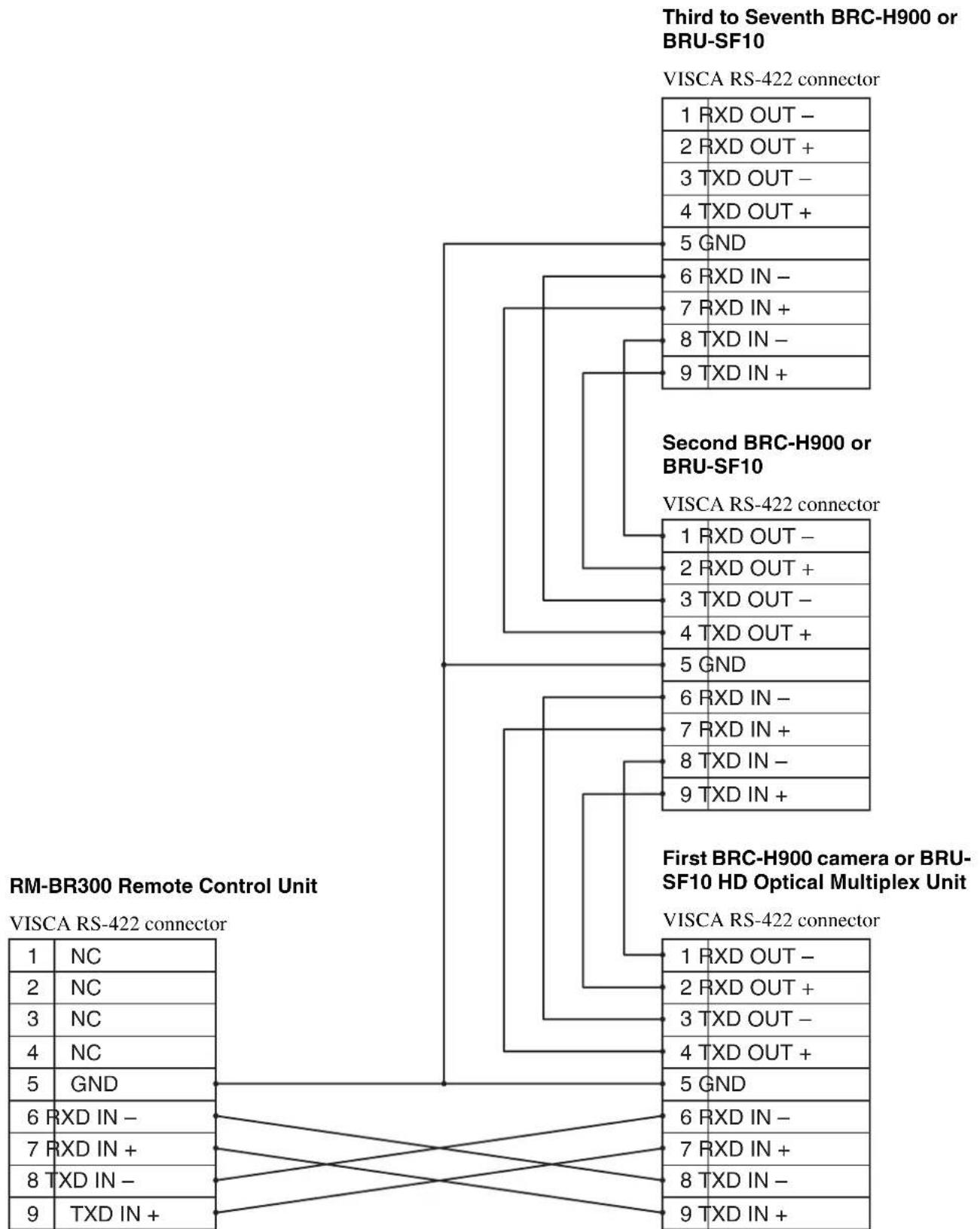
flowchart
graph TD
    A["Third to Seventh BRC-H900 or BRU-SF10"] --> B["VISCA RS-422 connector"]
    B --> C["1 RXD OUT -"]
    B --> D["2 RXD OUT +"]
    B --> E["3 TXD OUT -"]
    B --> F["4 TXD OUT +"]
    B --> G["5 GND"]
    B --> H["6 RXD IN -"]
    B --> I["7 RXD IN +"]
    B --> J["8 TXD IN -"]
    B --> K["9 TXD IN +"]
    L["Second BRC-H900 or BRU-SF10"] --> M["VISCA RS-422 connector"]
    M --> N["1 RXD OUT -"]
    M --> O["2 RXD OUT +"]
    M --> P["3 TXD OUT -"]
    M --> Q["4 TXD OUT +"]
    M --> R["5 GND"]
    M --> S["6 RXD IN -"]
    M --> T["7 RXD IN +"]
    M --> U["8 TXD IN -"]
    M --> V["9 TXD IN +"]
    W["First BRC-H900 camera or BRU-SF10 HD Optical Multiplex Unit"] --> X["VISCA RS-422 connector"]
    X --> Y["1 RXD OUT -"]
    X --> Z["2 RXD OUT +"]
    X --> AA["3 TXD OUT -"]
    X --> AB["4 TXD OUT +"]
    X --> AC["5 GND"]
    X --> AD["6 RXD IN -"]
    X --> AE["7 RXD IN +"]
    X --> AF["8 TXD IN -"]
    X --> AG["9 TXD IN +"]
NC = No Connection
Using the VISCA RS-422 Connector Plug
1 Insert a wire (AWG Nos. 28 to 18) into the desired wire opening on the VISCA RS-422 connector plug, and tighten the screw for that wire using a flat-head screwdriver.
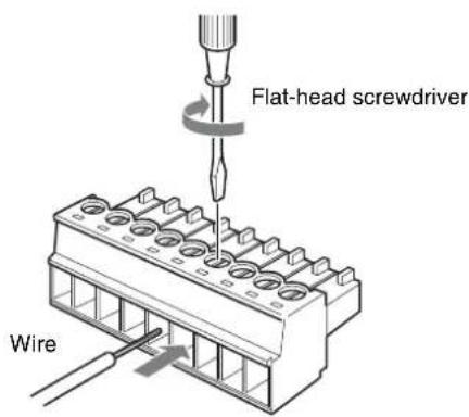
2 Insert the VISCA RS-422 connector plug into the VISCA RS-422 connector.
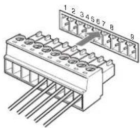
To remove the connector plug
Grasp both ends of the VISCA RS-422 connector plug and pull it out as shown in the illustration.
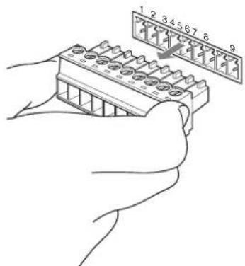
Notes
- In order to stabilize the voltage level of the signal, connect both ends to GND.
- When the connections using the VISCA RS-422 connectors are made, the VISCA RS-232C connection is not available.
- The maximum connection distance with the VISCA RS-422 connection is approximately 1,200 m (3,937 feet).
Menu principal ......29
natural_image
Line drawing of a mechanical device with no visible text or symbolsnatural_image
Line drawing of a rectangular electronic device with coiled cable and connector (no text or symbols)natural_image
Line drawing of a cord with two plug connectors (no text or symbols)natural_image
Line drawing of a plug and cable with two leads (no text or symbols)Télécommande (1)
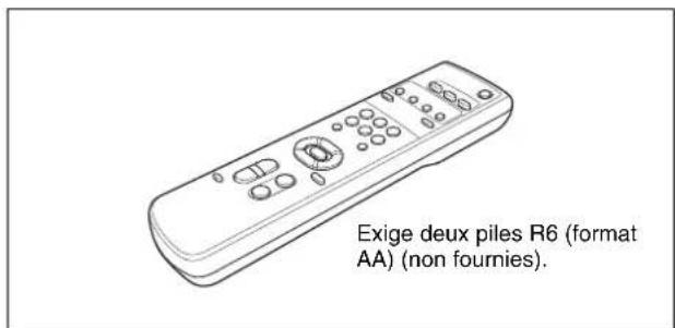
natural_image
Technical line drawing of a mechanical component with cutouts and mounting holes (no text or symbols)natural_image
Technical line drawing of a circular mechanical component with internal cavities and mounting holes (no text or symbols)natural_image
Line drawing of a coiled cable or wire with two connectors (no text or symbols)Vis ⊕M3 × 8 (7)/vis inoxydable ⊕M4 × 8 (1)

natural_image
Two identical mechanical screw or nut diagrams with threaded ends, shown from different angles (no text or symbols)natural_image
Isometric line drawing of a connector pinout (no text or symbols)natural_image
Simple line drawing of a 3D mechanical bracket or bracket (no text or symbols)Mode d'emploi (1)
Produits en option
natural_image
Line drawing of a joystick controller with handle and control panel (no text or symbols)natural_image
Line drawing of an electronic device with ports and connectors (no text or symbols)natural_image
Line drawing of a rectangular electronic device with multiple ports and connectors (no text or symbols)natural_image
Line drawing of a computer drive chassis with ports and connectors (no text or symbols)natural_image
Line drawing of a rectangular electronic device with mounting holes and a small internal component (no text or symbols)natural_image
Illustration of a coiled cable with two connectors and a small connector (no text or symbols)natural_image
Line drawing of a rectangular electronic device with ports and indicator lights (no text or symbols)Sert aux commandes VISCA.
16Prises AUDIO OUT L/R
| <COLOR> | |
| >WHITE BALANCE | AUTO |
| SPEED | 3 |
| OFFSET | 0 |
| MATRIX | ON |
| SELECT | STD |
| LEVEL | 0 |
| PHASE | 00 |
| R-G | 00 |
| R-B | 00 |
| G-R | 00 |
| G-B | 00 |
| B-R | 00 |
| B-G | 00 |
WHITE BALANCE
| (KNEE) | |
| >SETTING | DN |
| AUTO KNEE | OFF |
| POINT | 090 |
| SLOPE | 00 |
| KNEE SAT LEVEL | 50 |
SETTING
SELECT
natural_image
Line drawing of a Standby s'allume device with no text or symbols on the device itselfMise sous tension
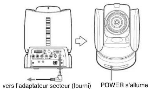
natural_image
Line drawing of a Standby clignote device (no text or symbols on the device itself)Zoom
natural_image
Line drawing of a portable electronic device with ports and cables, no text or symbols presentnatural_image
Line drawing of a portable electronic device with control panel and buttons (no text or symbols)natural_image
Line drawing of a desktop computer setup with monitor, keyboard, and mouse (no text or symbols)Remarques
natural_image
Illustration of two hands operating a camera with no visible text or symbols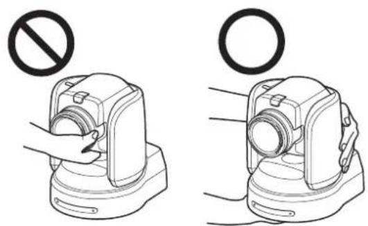
natural_image
Illustration of two mechanical devices with a prohibition symbol above them, no text or labels present.natural_image
Technical line drawing of a mechanical device with mounting holes and a coiled component (no text or symbols)natural_image
Technical line drawing of a mechanical device with mounting holes and cylindrical components (no text or symbols)natural_image
Line drawing of a portable electronic device with control panel and ports (no text or symbols)Remarques
natural_image
Line drawing of a portable kitchen appliance with control panel and buttons (no text or symbols)natural_image
Line drawing of a portable electronic device connected to a rectangular device via cable (no text or symbols)Operation Guide for Optional IP Control (1)
Face inférieure
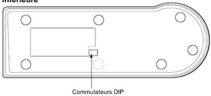
natural_image
Technical drawing of a rectangular electronic component with mounting holes and a dimension label (no text or symbols beyond measurement)Face avant
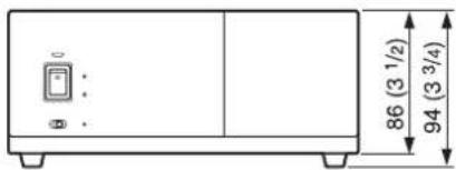
Unité : mm (pouces)

Annexe
Menú principal ......28
Menús de ajuste 28
natural_image
Line drawing of a mechanical device with no visible text or symbolsnatural_image
Line drawing of a rectangular electronic device with coiled cable and connector (no text or symbols)natural_image
Line drawing of a cord with two plug connectors (no text or symbols)Modelo para Europa
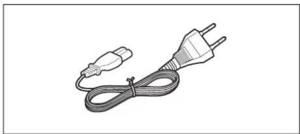
natural_image
Line drawing of a plug and cable with two leads (no text or symbols)natural_image
Technical line drawing of a mechanical component with cutouts and mounting holes (no text or symbols)Soporte de techo (B) (1)
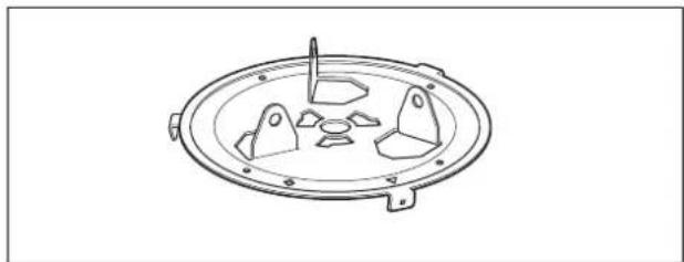
natural_image
Technical line drawing of a circular mechanical component with internal cavities and mounting holes (no text or symbols)natural_image
Line drawing of a coiled cable or wire with two connectors (no text or symbols)Tornillo ⊕M3 × 8 (7)/Tornillo de acero inoxidable ⊕M4 × 8 (1)

natural_image
Two identical mechanical screw or nut diagrams with threaded ends, shown from different angles (no text or symbols)natural_image
Isometric line drawing of a 3-pin electrical connector (no text or symbols)natural_image
Simple line drawing of a mechanical bracket or connector (no text or symbols)natural_image
Line drawing of a joystick controller with handle and control panel (no text or symbols)natural_image
Line drawing of an electronic device chassis with ports and connectors (no text or symbols)natural_image
Line drawing of a device rear panel with ports and connectors (no text or symbols)natural_image
Line drawing of a computer drive chassis with ports and connectors (no text or symbols)natural_image
Line drawing of a rectangular electronic device with mounting holes and a small internal component (no text or symbols)natural_image
Illustration of a coiled cable with connectors and a small connector (no text or symbols)natural_image
Simple line drawing of a rectangular electronic device with ports and indicator lights (no text or symbols)13 Conector → RGB/COMPONENT
15 Conector VISCA RS-232C OUT
21 Conector DC IN 12V
24 Conector TALLY/CONTACT
26 Conector DC IN 12V
12 Conector RGB/COMPONENT
14 Conector VISCA RS-232C OUT
1 Conector SDI MONITOR OUT (tipo BNC)
-1,0,-0,5,0,+0,5 y+1,0.
| <COLOR> | |
| >WHITE BALANCE | AUTO |
| SPEED | 3 |
| OFFSET | 0 |
| MATRIX | ON |
| SELECT | STD |
| LEVEL | 0 |
| PHASE | 00 |
| R-G | 00 |
| R-B | 00 |
| G-R | 00 |
| G-B | 00 |
| B-R | 00 |
| B-G | 00 |
WHITE BALANCE
natural_image
Line drawing of a vintage camera with visible lens and screen (no text or symbols)STANDBY se enciende.
natural_image
Line drawing of a camera with lens and side panels (no text or symbols)STANDBY parpadea.
Uso del zoom
natural_image
Line drawing of a portable electronic device with ports and control panel, showing signal flow arrows (no text or symbols)natural_image
Line drawing of a portable electronic device with control panel and buttons (no text or symbols)natural_image
Line drawing of a desktop computer setup with monitor, keyboard, mouse, and camera (no text or symbols)Notas
natural_image
Illustration of hands holding a camera with a prohibition symbol above (no text or labels)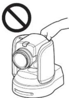
natural_image
Illustration of a hand holding a camera with a prohibition symbol above (no text or labels)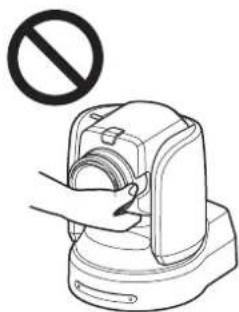
natural_image
Illustration of a hand using a device to press a circular component, with no text or symbols present.