IC800T - Speaker KLIPSCH - Free user manual and instructions
Find the device manual for free IC800T KLIPSCH in PDF.
Download the instructions for your Speaker in PDF format for free! Find your manual IC800T - KLIPSCH and take your electronic device back in hand. On this page are published all the documents necessary for the use of your device. IC800T by KLIPSCH.
USER MANUAL IC800T KLIPSCH
2. KEEP these instructions.
3. HEED all warnings.
4. FOLLOW all instructions.
5. DO NOT use this apparatus near water.
6. CLEAN ONLY with dry cloth or lightly damped cloth.
7. DO NOT block any ventilation openings. Install in accordance
with the manufacturer’s instructions.
8. DO NOT install near any heat sources such as radiators, heat registers,
stoves, or other apparatus (including amplifiers) that produce heat.
9. ONLY USE attachments/accessories specifically designed
for this application
10. USE only with a cart, stand, tripod, bracket, or table specifically
designed for this application, or sold with the apparatus. When a cart is used, use caution when moving the cart/apparatus combination to avoid injury from tip-over.
11. DO NOT expose this apparatus to dripping or splashing and ensure that
no objects filled with liquids, such as vases, are placed on the apparatus.
12. DO NOT modify or alter in any way.
13. SWITCH OFF amplifier prior to connecting speakers.
14. DO NOT hang or suspend any items from this apparatus.
The exclamation point, within an equilateral triangle, is intended to alert the user to the presence of important operating and mainte- nance (servicing) instructions in the literature accompanying the product. The lightning flash with arrowhead symbol within an equilateral triangle is intended to alert the user to the presence of uninsu- lated “dangerous voltage” within the product’s enclosure that may be of sufficient magnitude to constitute a risk of electrical shock to persons.
WARNING: To reduce the risk of fire or electrical shock, do not expose
this apparatus to rain or moisture.
WARNING: No naked flame sources – such as candles – should be
placed on the product.
WARNING: The apparatus is not designed to be used for any type of
moving or lifting installation.
WARNING: For Indoor use only.
WARNING: Installation must be done by qualified personnel to
appropriate standards and/or building codes. IMPORTANT SAFETY INSTRUCTIONSWARNING: Neglect to follow the safety and installation instructions may cause malfunctions resulting in property damage and personal injury.
WARNING: Do Not Open! Risk of Electrical Shock.
Voltages in this equipment are hazardous to life. No user-serviceable parts inside. Refer all servicing to qualified service personnel. Klipsch recommends that only qualified personnel install its loudspeaker systems. At all times, be sure that adequate safety factors are observed. Due to the weight and size of the components involved, potential damage could occur if devices were to become unattached. The included tile-bridge must be used when installing into suspended ceilings. Use the seismic tab as a secondary means of support. In some areas, using the seismic tab is required by code.CONTENTS IC-400-T IC-525-T IC-650-T IC-800-T IC-500-T-SC x2 Speaker Modules x2 Grilles x2 Reinforcement Rings x4 Rails x2 Cardboard Cutout Template and Paint Mask x8 Screws (Attach Rails to Reinforcement Ring) x2 3/4” Adapter fittings x1 Speaker Module x1 Grille x1 Reinforcement Ring x2 Rails x1 Cardboard Cutout Template and Paint Mask x4 Screws (Attach Rails to Reinforcement Ring) x1 3/4” Adapter fitting
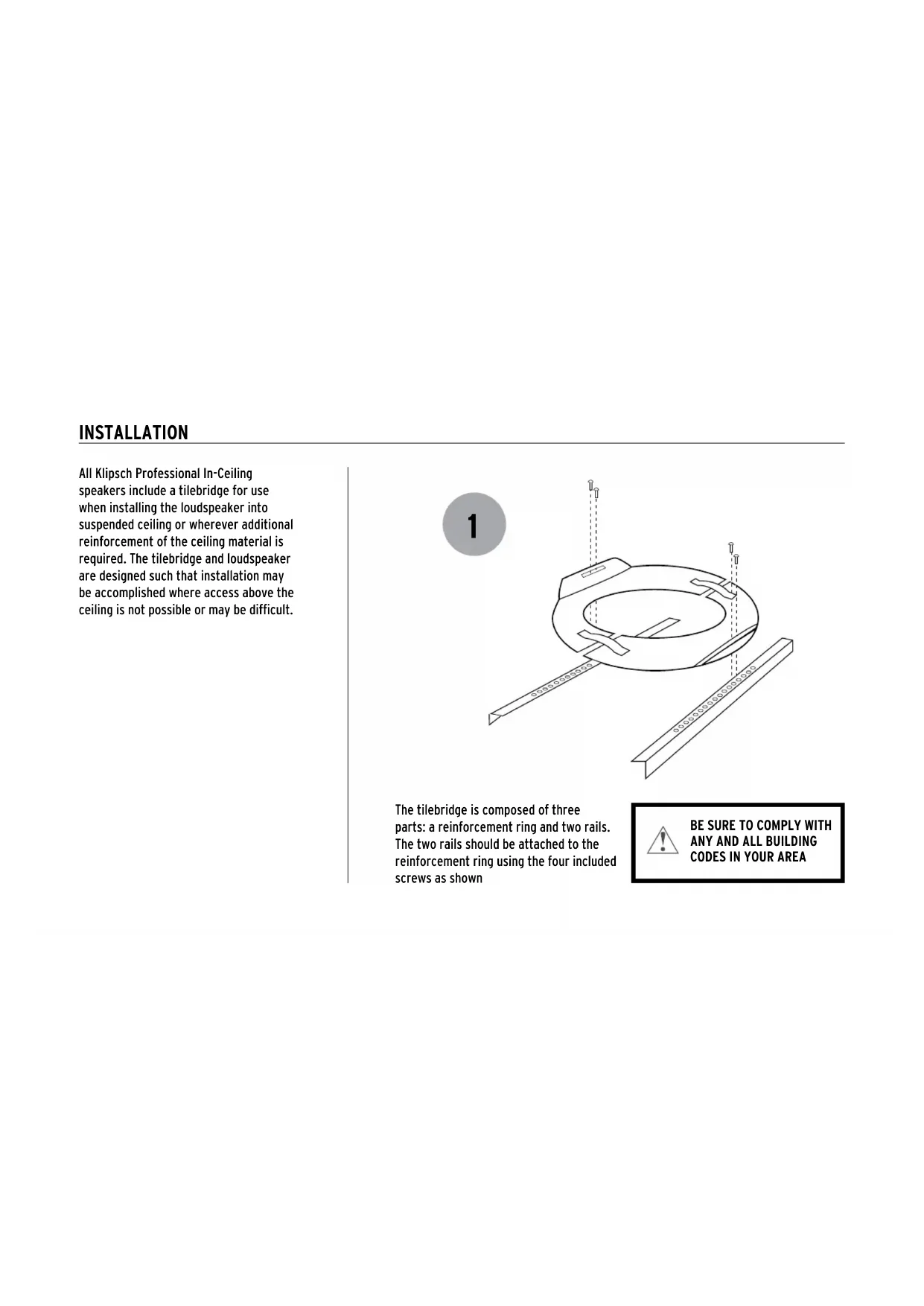
All Klipsch Professional In-Ceiling speakers include a tilebridge for use when installing the loudspeaker into suspended ceiling or wherever additional reinforcement of the ceiling material is required. The tilebridge and loudspeaker are designed such that installation may be accomplished where access above the ceiling is not possible or may be difficult. The tilebridge is composed of three parts: a reinforcement ring and two rails. The two rails should be attached to the reinforcement ring using the four included screws as shown2 3 INSTALLATION
TEMPLATE TEMPLATE To install your speaker cut a hole in the ceiling using either the cardboard cutout template provided with your speakers or consult the measurements shown. Pull wiring through hole. IC-400-T, IC-525-T, IC-500-T ø9.125” IC-650-T ø10.125” IC-800-T ø12.625”4 To Install the tilebridge, fold the rail side of the ring back upon itself using the spring tensioner on the reinforcement ring to allow insertion into the cutout hole. Once it is inserted into the cutout hole, release the reinforcement ring such that it unfolds back to its normal position. Position tilebridge over cutout hole, and insure that the tile rails rest on the t-grid struts.INSTALLATION The wiring compartment is intended as a termination point for the audio circuit. Access to the compartment is gained by removing the terminal cover located on the back of the speaker. (For the IC-500-T-SC, the terminal is located on the side of the speaker) The terminal cover will accept the appropriate conduit/wire adapter. Feed wires through conduit/wire adapter and connect to the input terminal according to the desired operation mode. Be sure to observe proper polarity. Replace the terminal cover and tighten the conduit/wire adapter to secure the wire.
FOR IC-500-T-SC ONLYInsert the speaker into the cutout hole. With a #2 Phillips screwdriver, tighten the four dog clamps until they are seated securely against the ceiling surface. Do not overtighten. 6 7INSTALLATION
3.75W 7.5W 15W 30W 30W 15W 7.5W
7.5Ω 7.5W 15W 30W 60W 60W 30W 15W
Stereo 60W For installations using 70V/100V input connection, set the switch on the front panel to the desired setting. For applications where 8 Ohm impedance is desired, the switch should be set to 8 Ohms. (Or 7.5 ohm for the IC-650-T) Note: The speaker comes from the factory set at the lowest output setting (high impedance). IC-650-T tap selectable
3.75W 7.5W 15W 30W 30W 15W 7.5W
7.5Ω 7.5W 15W 30W 60W 60W 30W 15W
Stereo 60W IC-525-T tap selectable IC-400-T tap selectable IC-500-T-SC tap selectable IC-800-T tap selectableUsing the flat of your hand, insert grille into speaker frame making sure it is securely seated and flush. SEISMIC TAB A seismic tab, located on the back of the speaker, is used as a secondary security point. Some construction codes may require its use. To utilize the seismic tab, run a support wire from a secure point in the ceiling and attach it to the tab. Be sure to consult the construction codes in your area. Klipsch recommends the use of this tab in all installations as a secondary means of support.
3.75W 7.5W 15W 30W 30W 15W 7.5W
7.5Ω 7.5W 15W 30W 60W 60W 30W 15W
3.75W 7.5W 15W 30W 30W 15W 7.5W
7.5Ω 7.5W 15W 30W 60W 60W 30W 15W
3.75W 7.5W 15W 30W 30W 15W 7.5W
7.5Ω 7.5W 15W 30W 60W 60W 30W 15W
3.75W 7.5W 15W 30W 30W 15W 7.5W
7.5Ω 7.5W 15W 30W 60W 60W 30W 15W
3.75W 7.5W 15W 30W 30W 15W 7.5W
7.5Ω 7.5W 15W 30W 60W 60W 30W 15W
3.75W 7.5W 15W 30W 30W 15W 7.5W
7.5Ω 7.5W 15W 30W 60W 60W 30W 15W
3.75W 7.5W 15W 30W 30W 15W 7.5W
7.5Ω 7.5W 15W 30W 60W 60W 30W 15W
3.75W 7.5W 15W 30W 30W 15W 7.5W
7.5Ω 7.5W 15W 30W 60W 60W 30W 15W
3.75W 7.5W 15W 30W 30W 15W 7.5W
7.5Ω 7.5W 15W 30W 60W 60W 30W 15W
3.75W 7.5W 15W 30W 30W 15W 7.5W
7.5Ω 7.5W 15W 30W 60W 60W 30W 15W
3.75W 7.5W 15W 30W 30W 15W 7.5W
7.5Ω 7.5W 15W 30W 60W 60W 30W 15W
3.75W 7.5W 15W 30W 30W 15W 7.5W
7.5Ω 7.5W 15W 30W 60W 60W 30W 15W
93502 WOODVIEW TRACE, INDIANAPOLIS, IN, USA
©2015, Klipsch Group, Inc. Klipsch Group, Inc. is a wholly-owned subsidiary of Voxx International Corporation. Klipsch and Keepers of the Sound are trademarks of Klipsch Group, Inc., registered in the United States and other countries. V07 - 0504