Atrium SUB100 - Speaker POLK - Free user manual and instructions
Find the device manual for free Atrium SUB100 POLK in PDF.
User questions about Atrium SUB100 POLK
0 question about this device. Answer the ones you know or ask your own.
Ask a new question about this device
Download the instructions for your Speaker in PDF format for free! Find your manual Atrium SUB100 - POLK and take your electronic device back in hand. On this page are published all the documents necessary for the use of your device. Atrium SUB100 by POLK.
USER MANUAL Atrium SUB100 POLK
IMPORTANT SAFETY INSTRUCTIONS
This product was designed and manufactured to meet strict quality and safety standards. There are, however, some installation and operation precautions which you should be particularly aware of.
- Read Instructions. All the safety and operating instructions should be read before the system is operated.
- Retain Instructions. The safety and operating instructions should be retained for future reference.
- Heed Warnings. All warnings on the appliances and in the operating instructions should be adhered to.
- Follow instructions. All operating and use instructions should be followed.
- Attachments. Do not use attachments not recommended by the product manufacturer as they may cause hazards.
- Accessories. Do not place these appliances on an unstable cart, stand, tripod, bracket, or table. The audio/video products may fall, causing serious injury to a child or adult, and serious damage to the products. Use only with a cart, stand, tripod, bracket, or table recommended by the manufacturer, or sold with the appliances. Any mounting of the appliances should follow the manufacturer's instructions, and should use mounting accessories recommended by the manufacturer.
- Object and Liquid Entry. Never push objects of any kind into this product through openings, as they may touch dangerous voltage points or short out parts that could result in a fire or electric shock. Never spill liquid of any kind on this audio/video product.
-
Servicing. Do not attempt to service this product yourself, as opening or removing covers may expose you to dangerous voltage or other hazards. Refer all servicing to qualified service personnel.
-
Damage Requiring Service. Unplug this product from wall outlets and refer servicing to qualified service personnel under the following conditions:
a. If liquid has been spilled, or objects have fallen into the product.
b. If the product does not operate normally by following the operating instructions. Adjust only those controls that are covered by the operating instructions, as an improper adjustment of other controls may result in damage and will often require extensive work by a qualified technician to restore the product to its normal operation.
c. If the product has been dropped or the cabinet has been damaged.
d. When the product exhibits a distinct change in performance—this indicates a need for service. - Replacement Parts. When replacement parts are required, be sure the service technician has used replacement parts specified by the manufacturer or that the parts have the same characteristics as the original part. Unauthorized substitutions may result in fire, electric shock or other hazards.
- Safety Check. Upon completion of any service or repairs to this product, ask the service technician to perform safety checks to determine that the products are in proper operating condition.
Polk Audio specifies the recommended amplification range for each of its passive (non-amplified) loudspeakers. Typically that specification will be expressed as a range of power such as 20-200 Watts (per channel). It is important to understand what those numbers mean when choosing a receiver or amplifier for your Polk Audio loudspeakers. The lower number indicates the lowest continuous rated power that will yield acceptable performance in a typical listening environment. The higher number indicates the highest per channel power that should be used with your Polk Audio speakers. That number should not be confused with a "Power Handling" specification and it does not imply that the speaker will safely handle that full amount of power on a long-term basis. We specify a wide range of power ratings because not all electronics manufacturers use the same method for rating power. In fact, high quality lower-rated amplifiers sound better and play louder than low quality units with higher power rating.
Automobile horsepower is a good analogy. Your car probably has far more horsepower than it needs for your daily commune and is likely capable of going well over 120mph (190km/hr). Having that extra power is good for on-ramp acceleration and danger avoidance like getting away from brain-eating zombies) but that doesn't mean that it is advisable to operate your car on North American highways at full power and maximum speed for an extended period of time. Just ask your local state troper if you are in doubt. Similarly, we recommend using amplifiers and receivers with rated power above the power handling limits of our speakers because having extra power available for short term peaks is conducive to better sound quality, maximum dynamic range and effortless high volume output. But we strongly urge you not to use the full power of your amplifier or receiver for daily listening.
Ioudspeakers can be damaged when an amplifier, regardless of its wattage, is made to play at higher listening levels than its power can clearly produce. Operation at this level can result in very high levels of audible distortion originating in the amplifier, which can add a harsh, gritty sound to your listening material. If you hear distortion—turn the volume down or risk damaging your speakers. You can damage just about any speaker, regardless of power rating, if you drive an amplifier to or beyond the point of distortion.
PRODUCT DISPOSAL
Certain international, national and/or local laws and/or regulations may apply regarding the disposal of this product. For further detailed information, please contact the retailer where you purchased this product or the Polk Audio Importer/Distributor in your country. A listing of Polk Audio Importer/Distributors can be found on the Polk Audio website www.polkaudio.com or by contacting Polk Audio at 5601 Metro Drive, Baltimore, Maryland 21215, USA Phone: +1 410 358-3600.
TECHNICAL ASSISTANCE OR SERVICE
If, after following the hookup directions, you experience difficulty, please double-check all wire connections. Should you isolate the problem to the speaker, contact the authorized Polk Audio dealer where you made your purchase, or contact: Polk Audio Customer Service 800-377-7655 IN-T, 9am-8pm stt., US & Canada only or via email polkcs@polkaudio.com. Outside the US & Canada, call 410-358-3600. More detailed information including audio how to articles, FAQs and online manuals are available on our award-winning website: www.polkaudio.com.
PLACEMENT OPTIONS
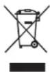
Atrium Series loudspeakers were created to live and play outdoors. Atriums have a wide dispersion pattern, and are also very efficient. This means your Atrium Series loudspeakers will deliver exceptional sound quality throughout a large listening area. However, if you want high sound levels in an outdoor setting with acoustic characteristics that differ from those of indoor conditions, we recommend multiple-pair setups.
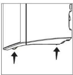
In addition to the placement locations typically used for outdoor loudspeakers, all Atrium Series loudspeakers have built-in stability feet, which allows the loudspeakers to be placed securely on a shelf or other flat horizontal surface.
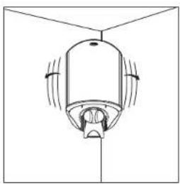
Please keep in mind that you'll maximize the useful life of your Atrium loudspeakers by locating them where they'll receive less exposure to the elements, under eaves for example. When locating your Atrium loudspeakers outdoors, take into account three factors: sound quality, convenience and exposure to the elements.
natural_image
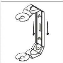
Simple line drawing of a ceiling-mounted device with directional arrows indicating airflow or movement (no text or symbols)FIGURE 1: Place the speaker in a corner for more bass output. Bracket attached to side wall.
natural_image
Diagram of a mechanical component with motion arrows indicating movement (no text or symbols)FIGURE 2: Place the speaker away from eaves and corners for less boss output.

natural_image
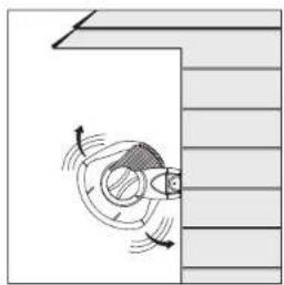
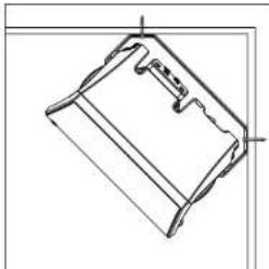
Pure technical diagram of a mechanical component without any text, numbers, or symbolsFIGURE 3: Place the speaker close under an eave for more bass output
natural_image
Simple line drawing of a curved mechanical part with two upward arrows indicating direction (no text or symbols)FIGURE 4: The Atrium's built-in stability feet ensure safe, secure placement on a shell of other flat surface.
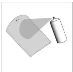
PREPARING TO PAINT
Before you paint, you will need:
- A spray can of primer paint (Krylon Sandable Spray Primer #1318).
- A spray can of the paint of your choice. Choose exterior grade paint if you plan to use the speakers outdoors.
- A paperclip or corkscrew (for removing the paintable grille).
- Masking tape.
- Paint mask to cover unpaintable parts (not included). To make an easy paint mask, use the grille as a template and cut a mask from heavy, nonporous Kraft paper.
-
Separate the parts of the speaker: Remove the brackets and bracket knobs. Remove the grille by carefully hooking it with a bent paper clip and pulling it gently away from the cabinet [figure 5].
-
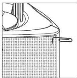
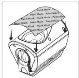
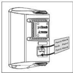
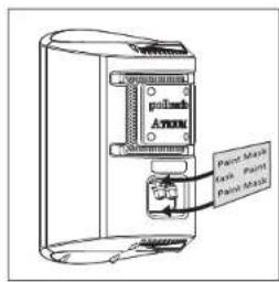
Mask off the binding posts on the back of the speaker [figure 6], the end panels and bracket knobs, and carefully mask off the front of the speakers to protect the drivers and baffles while painting [figure 7]. The grille has a logo on it, which you may mask off should you choose not to paint over it.
natural_image
Line drawing of a mechanical component with textured surface and handle (no text or symbols)FIGURE 5: Remove the grille using a paper clip.

text_image
Paint Mask Paint Mask Paint MaskFIGURE 6: Mask the binding posts on the rear of the speaker.
text_image
Paint Mask Paint Mask Paint Mask Paint Mask Paint Mask Paint Mask Paint Mask Paint Mask Paint Mask Paint Mask Paint Mask Paint Mask Paint Mask Paint Mask Paint Mask Paint Mask Paint Mask Paint Mask Paint Mask Paint Mask Paint Mask Paint Mask Paint Mask Paint Mask Paint Mask Paint Mask Paint Mask Paint Mask Paint Mask Paint Mask Paint Mask Paint Mask Paint Mask Paint Mask Paint Mask Paint Mask Paint Mask Paint Mask Paint Mask Paint Mask Paint Mask Paint Mask Paint Mask Paint Mask Paint Mask Paint Mask Paint Mask Paint Mask Paint Mask Paint Mask Paint Mask Paint MaskFIGURE 7: Mask the drivers and baffles.
PAINTING THE CABINET, BRACKET KNOBS & BRACKET
- Apply two thin coats of primer to the cabinet and knobs. The bracket does not require a primer.
- Only after the primer is completely dry should you apply the finish color [figure 8].
- Do not remove the masking material (not included) until the paint is completely dry.
- Do not reattach the speaker to the bracket until the bracket is mounted. Try to handle any freshly painted parts as little as possible.
PAINTING THE GRILLE
- Atrium loudspeaker grilles have an even, protective powder coating. This powder coating is an ideal primer. The grille has a logo pod, which you may mask off or paint right over.
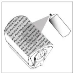
- Using spray paint, spray two thin coats of finish color [figure 9]. If you're using a compressor and spray gun, use the finest, most diffuse setting. Be careful not to fill the holes in the grille with paint.
- When the paint is completely dry, carefully fit the grille into its recess so that it just rests on the cabinet. Starting with one corner, work around the speaker and push the grille into the grille notch a little at a time.
Be gentle; the grille may be easily bent by rough handling.
text_image
Pancet in Parch, No. and Parch, Part 1, Part 2, Part 3 and Parch, Part 4, Part 5, Part 6 and Parch, Part 7, Part 8, Part 9 and Parch, Part 10, Part 11, Part 12 and Parch, Part 13, Part 14, Part 15 and Parch, Part 16, Part 17, Part 18, Part 19 and Parch, Part 20, Part 21, Part 22, Part 23, Part 24FIGURE 8: After priming, apply thin coats of finish color.
natural_image
Illustration of a spray can and a tilted rectangular object (no text or symbols)FIGURE 9: Paint the grille. Use thin coats of spray paint. Do not block grille holes with paint.
MOUNTING OPTIONS (SAFETY FIRST)
When installing Atrium loudspeakers note the weight of your particular model and the weight bearing tolerance of the material to which you're mounting the speaker. If you're not sure of a safe way of mounting your speakers, please consult a professional installer, your authorized Polk Audio dealer or a building contractor.
You'll maximize the useful life of your Atrium loudspeakers by placing them where they'll receive less exposure to the elements. If extreme weather conditions are expected, we recommend storing your speakers indoors. Look for the best overall compromise between sound quality, convenience and exposure. Never compromise safety.
The Atrium's Speed-Lock ^® mounting bracket enables you to mount the speaker either horizontally or vertically. The Speed-Lock bracket holds the speaker in place so you can easily aim the speaker to deliver the best possible sound in a variety of situations. Follow the steps below to safely secure the brackets and speakers.
Installing Atrium Series loudspeakers requires basic skills in using tools such as a drill and screwdriver. If you are in doubt that you possess the necessary skills or tools, consult your Polk Audio dealer, or a professional installer.
Horizontal & Vertical Mounting
- Verify the material on which you plan to mount the speakers (plaster, drywall, paneling, stone, etc.) can support the weight of the speakers:
Speaker Weights
Atrium4 3.6lbs / 1.63kg each
Atrium5 4.6lbs / 2.09kg each
Atrium6 5.4lbs / 2.45kg each
Atrium7 8lbs / 3.63kg each
Atrium8SDI 9.7lbs / 4.4kg each
- Ensure the locations you select do not conceal electrical wiring or plumbing.
- Before you install the speaker, hold it in the chosen location to make sure it safely clears obstacles such as ceiling, adjacent walls, corners, beams, lighting fixtures and door/window frames.
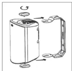
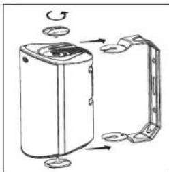
- Using the keyhole slots in the bracket as a template, mark the installation location of the two keyhole slots with a pencil. You can do this by removing the bracket knobs on the top and bottom of the speaker and removing the bracket [figure 10].
- Position the bracket so that the small ends of the keyhole slots are facing "up" according to the direction of installation.
natural_image
Diagram of a device with rotating components and mounting base (no text or symbols)FIGURE 10: Turn the bracket knobs to remove the bracket assembly.
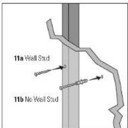
- If you are certain there is a stud behind the wall surface, drive #10 screws (not included) through the wall and into the stud [figure 11a].
- If there is no stud behind the wall at the chosen location, install #10 wall anchors (not supplied) into the wall by following the wall-anchor-manufacturer's instructions. Always use two wall anchors and two screws per speaker [figure 11b].
- Drive the screws into the stud or wall anchors, leaving screw heads protruding 1/8"-1/4" (3mm-6mm).
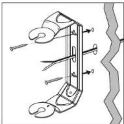
- If you're feeding speaker wire through a hole in the wall behind the bracket, pull this speaker wire through the hole in the bracket before mounting the bracket [figure 12].
- Screw the bracket directly into a weight-bearing stud on the mounting surface. Place the screws securely in the smaller end of the keyhole slot. Do not leave screw heads protruding.
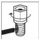
Note: All Atrium loudspeaker cabinets have molded ramps, which guide the speaker bracket onto threaded protrusions to which the bracket knobs attach.
- Screw the bracket knobs into the protrusions but do not lighten them securely.
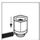
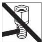
- Secure the speaker to the bracket by sliding the speaker between the bracket arms. The built-in ramps will spread the bracket slightly and guide the ends of the bracket onto the threaded protrusions. A ratcheting system holds the speaker in place and helps you fine tune how you want to aim it. [figure 14]
- Secure the loudspeaker to the bracket by tightening the adjusting bracket knobs.
text_image
11a Wall Stud 11b No Wall StudFIGURE 11a & 11b: Use #10 screw for wall stud, use #10 wall anchors and screw for no wall stud.
natural_image
Technical line drawing of a mechanical clamp or hook assembly with no visible text or symbolsFIGURE 12: Feed speaker wire from wall through bracket wire hole for easy mounting.
natural_image
Diagram of a mechanical clamp or bracket with downward arrows indicating force or movement (no text or symbols)FIGURE 13: Slide the bracket down on the screw heads to catch the keyhole slots.
natural_image
Diagram of a water heater with rotating components and mounting base (no text or symbols)FIGURE 14: Turn the bracket knobs to remove the bracket assembly.
natural_image
Technical line drawing of a mechanical component or bracket (no text or symbols)FIGURE 15: Installation of the 45° bracket.
text_image
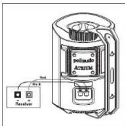
polisado ACTION Receptor Red BlackFIGURE 16: Make speaker connection using binding posts.
- Tug gently on the speaker to make certain that the screws and bracket are properly aligned and that the wall anchors are secure.
- If the bracket is not held snug against the wall by the screw heads, remove the speaker from the wall, drive the screws in a little further and then remount the speaker.
- Once the speaker is mounted, the bracket knobs can be loosened to "aim" the speaker, and then hand tightened to keep the speaker angled correctly.
VERTICAL MOUNT AIMED 45° DOWN
The Atrium Series mounting bracket is designed so the speakers may be mounted in a vertical 45° downward firing position [Figure 15].
Use an anchoring device that can support the weight of your Atrium model and be sure the material you are mounting the loudspeaker to can support its weight.
RECEIVER HOOKUP
Follow the hookup directions included with your receiver. Strip 1/2° of insulation from each of the two conductors of the wire to expose the bare metal and twist each of the conductors into a single un-frayed strand (so you have two unfrayed strands).
Note that one of the terminals on the rear of each speaker is red (+) and the other is black (−). Make certain that you connect the wire from the red terminal of your amplifier or receiver to the red terminal on your speaker; and the wire from the black terminal of your amplifier or receiver to the black terminal on your speaker [figure 16]. Most wire has some indicator (such as color-coding, ribbing or writing) on one of the two conductors to help you maintain consistency.
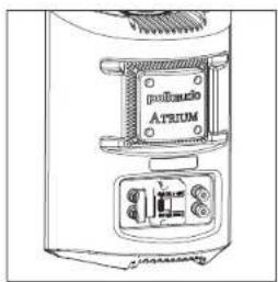
ATRIUM8SDI DUAL INPUT/SINGLE INPUT SWITCH
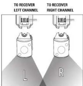
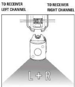
The Atrium8scl has a patented dual input/single input switch, this switch enables the Atrium8scl to be used either as a single high-performance stereo loudspeaker, or the left-or-right speaker in a high performance stereo pair [Figure 17].
text_image
polisolo ATRUMFIGURE 17: Rear view of the Atrium850.
text_image
TO RECEIVER LEFT CHANNEL TO RECEIVER RIGHT CHANNEL L RSTEREO PAIR
text_image
TO RECEIVER LEFT CHANNEL TO RECEIVER RIGHT CHANNEL L + RSINGLE HOOKUP
USING 5-WAY BINDING POSTS
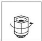
Loosen hex nut
Insert speaker wire through hole
Tighten hex nut.
Do not insert insulated section of speaker wire
Français
IMPORTANTES CONSIGNES DE SÉCURITÉ
OPTIONS D'INSTALLATION
natural_image
Simple line drawing of a ceiling-mounted device with directional arrows indicating motion (no text or symbols)natural_image
Diagram of a mechanical or electrical component with directional arrows indicating motion, no text or symbols presentnatural_image
Architectural line drawing of a window frame with a circular vent (no text or symbols)natural_image
Pure technical diagram of a curved mechanical part with two upward arrows indicating direction (no text or symbols)natural_image
Diagram of a container with a lid and handle, showing internal structure (no text or symbols)FIGURE 5: Retirez la grille en utilisant un trombone.
text_image
Polish Arm Paint Mask Paint Masktext_image
Butter is Spent to Pant, Part, Part, Part, Part, Part, Part, Part, Part, Part, Part, Part, Part, Part, Part, Part, Part, Part, Part, Part, Part, Part, Part, Part, Part, Part, Part, Part, Part, Part, Part, Part, Part, Part, Part, Part, Part, Part, Part, Part, Part, Part, Part, Part, Part, Part, Part, Part, Part, Part, Part, Pant Part and Part are not and the other parts are not and the other parts are not and the other parts are not and the other parts are not and the other parts are not and the other parts are not and the other parts are not and the other parts are not and the other parts are not and the other parts are not and the other parts are not and the other parts are not and the other parts are not and the other parts are not and the other parts are also and the other parts are also and the other parts are also and the other parts are also and the other parts are also and the other parts are also and the other parts are also and the other parts are also and the other parts are also and the other parts are also and the other parts are also and the other parts are also and the other parts are also and the other parts are also and the other parts are also an and and and and and and and and and and and and and and and and and and and and and and and and and and and and and and and and and and and and and and and and and and and and and and and and and and annatural_image
Illustration of a spray can and a curved surface, no text or symbols presentnatural_image
Diagram of a device with rotating components and mounting base (no text or symbols)Atrium6 5.4lbs / 2.45kg ch.
Atrium7 8lbs / 3.63kg ch.
Atrium8s01 9.7lbs / 4.4kg ch.
text_image
Technical diagram of a mechanical clamp or spring mechanism with labeled parts and directional arrowsnatural_image
Diagram of a mechanical clamp or bracket with downward arrows indicating force or movement (no text or symbols)natural_image
Diagram of a portable air purifier with rotating components and mounting base (no text or symbols)natural_image
Technical line drawing of a mechanical component or bracket (no text or symbols)text_image
polisado ATRUM 3rd + ReceiverFIGURE 16: Connecter le fil de haut parlour aux bornas.
natural_image
Diagram of a ceiling-mounted device with directional arrows indicating airflow or movement (no text or symbols)natural_image
Diagram of a mechanical component with rotational motion arrows, no text or symbols presentnatural_image
Technical line drawing of a mechanical component with no visible text or symbolsnatural_image
Simple line drawing of a curved object with two upward arrows indicating direction (no text or symbols)natural_image
Line drawing of a mechanical component with textured surface and handle (no text or symbols)FIGURA 5: Quite la repilla con un clip.
text_image
palmask Exch Paint Palm Masktext_image
Spray for Paper and Spray for Paper (Pent) and Spray for Paper (Pent) and Spray for Paper (Pent) and Spray for Paper (Pent) and Spray for Paper (Pent) and Spray for Paper (Pent) and Spray for Paper (Pent) and Spray for Paper (Pent)natural_image
Illustration of a spray can and a tilted rectangular object (no text or symbols)natural_image
Diagram of a mechanical device with rotating components and mounting base (no text or symbols)natural_image
Technical diagram of a mechanical clamp or spring mechanism with no visible text or symbolsnatural_image
Diagram of a mechanical clamp or bracket with downward arrows indicating force or movement (no text or symbols)natural_image
Diagram of a portable air purifier with mechanical components and airflow arrows (no text or labels)natural_image
Technical line drawing of a mechanical component or bracket (no text or symbols)text_image
Attire Receiver Blacknatural_image
Simple line drawing of a ceiling-mounted device with no text or symbolsnatural_image
Diagram showing a rotating mechanical component with motion arrows, no text or symbols presentnatural_image
Simple line drawing of a door with a circular opening and horizontal lines, no text or symbols present.natural_image
Simple line drawing of a curved mechanical part with two upward arrows indicating direction (no text or symbols)natural_image
Line drawing of a mechanical component with layered structure and textured base (no text or symbols)text_image
Pancils in Parch and Parched Parched and Parched Parched and Parched Parched and Parched Parched and Parched Parched and Parched Parched and Parched Parched and Parched Parched and Parched Parched and Parched Parched and Parched Parched and Parched Parched and Parched Parchednatural_image
Illustration of a spray can spraying onto a flat surface (no text or symbols)natural_image
Diagram of a device with rotating arm and clamping mechanism (no text or symbols)natural_image
Technical diagram of a mechanical clamp or spring mechanism with no visible text or symbolsnatural_image
Diagram of a mechanical clamp or bracket with downward arrows indicating force or movement (no text or symbols)natural_image
Diagram of a portable air purifier with rotating buttons and mounting base (no text or symbols)natural_image
Technical line drawing of a mechanical component or bracket (no text or symbols)text_image
Attire Receiver Black| Atrium4 | Atrium5 | Atrium6 | |
| Driver Complement 4 1/2" [114mm] mineral filled 5" [177mm] mineral filled 5 1/2" [133mm] Dynamic BalanceDynamic Balance® polymer cone, Dynamic Balance polymer cone, aerated polypropylene cone,rubber surround, 3/4" [19mm] rubber surround, 3/4" [18mm] rubber surround, 1" [26mm]anodized aluminum dome tweeter anodized aluminum dome tweeter anodized aluminum dome tweaterew/ rubber surround and w/ rubber surround and neodymium motor structure | |||
| Frequency Response /kHz-2kHz | 6GHz-2kHz | 6GHz-2kHz | |
| Recommended Power | 10-80W continuous | 10-100W continuous | 10-100W continuous |
| Impedance | Compatible w/ 8 Ohm outputs | Compatible w/ 8 Ohm outputs | Compatible w/ 8 Ohm outputs |
| Efficiency (dB 1w/1m) | 85dB | 90dB | 90dB |
| Available Finishes | Black & White | Black & White | Black & White |
| EnvironmentalStandents | ASTM D5894-UV SaltFog, Mil Standard 810Immersion, Mil-Std 883Method 10C9.9 for salt Method 100S.8 for saltand corrosion &Polk Audio Certification | ASTM D5894-UV SaltFog, Mil Standard 810Immersion, Mil-Std 883Method 10C9.9 for salt and corrosion &Polk Audio Certification | ASTM D5894-UV SaltFog, Mil Standard 810Immersion, Mil-Std 883Method 10C9.9 for salt and corrosion &Polk Audio Certification |
| Cabinet material | Mineral filledpolypropylene | Mineral filledpolypropylene | Mineral filledpolypropylene |
| Grills & Bracketmaterial | powder coatedaluminum | powder coatedaluminum | powder coatedaluminum |
| Hardware | Brass or stainless steel | Brass or stainless steel | Brass or stainless steel |
| Terminals | Gold plated 5-waybinding posts | Gold plated 5-waybinding posts | Gold plated 5-waybinding posts |
| Mounting Options 180" Spread-lock "mounting | 180" Spread-lock mounting | 180" Spread-lock mounting | |
| Dimensions(w/ bracket & knobs) | 8.5/8" H x 5 11/16" W x 11/16" D(21.9cm H x 14.4cm W x 17cm D) | 10.5/16" H x 6 3/4" W x 7 3/4" D(26.2cm H x 17.1cm W x 18.7cm D) | 11.11/16" H x 7 11/16" W x 8 3/4" D(23.7cm H x 19.5cm W x 22.2cm D) |
| Product Weight | 3.6lbs / 1.63kg (each) | 4.6lbs / 2.09kg (each) | 5.4lbs / 2.45kg (each) |
| Shipping Weight | 9.5lbs /4.1 kg (pair) | 11.5lbs / 5.0kg (pair) | 16lbs / 7.0kg (pair) |
SPECIFICATIONS
| Atrium7 | Atrium8soi | |
| Driver Complement | 6 1/2" (165mm) Dynamic Balance aerated polypropylene cone, rubber surround, 1" [25mm] anatized aluminum dome tweeler anatided aluminum dome tweeler w/rubber surround and neodymium motor structure | 6 1/2" (165mm) Dual Voice Coil Dynamic Balance aerated polypropylene cone, rubber surround, Two 1" [25mm] |
| 45Hz-27kHz | ||
| Recommendation Power | 10-125W continuous | 10-125W x 2 continuous |
| Impedance | Compatible w/ 8 Ohm outputs | Compatible w/ 8 Ohm outputs |
| Efficiency (dB 1w/1m) | 91dB | 91dB |
| Available Finishes | Black & White | Black & White |
| Environmental Standards | ASTM De884-UV Salt Fog, Mill Standard 810 Immersion, Mill-Std 883 Method 1008.8 for salt and corrosion & Polk Audio Certification | ASTM De884-UV Salt Fog, Mill Standard 810 Immersion, Mill-Std 883 Method 1009.8 for salt and corrosion & Polk Audio Certification |
| Cabinet material | Mineral filled polypropylene | Mineral filled polypropylene |
| Grills & Bracket material | powder coated aluminum | powder coated aluminum |
| Hardware | Brass or stainless steel | Brass or stainless steel |
| Terminals | Gold plated 5-way binding posts | Grid plated 5-way binding posts |
| Mounting Options 180° Speed-lock mounting | 180° Speed-lock mounting | |
| Dimensions (w/ bracket & kncbs) | 12 /8" H x B 1/2" W x B 3/16" D (32.7cm H x 21.6cm W x 23.3cm D) | 12 /8" H x B 1/2" W x B 3/16" D (32.7cm H x 21.6cm W x 23.3cm D) |
| Product Weight | 8lbs / 3.63kg (each) | 9.7lbs / 4.4kg (each) |
| Shipping Weight | 21.5lbs / 9.4kg (pair) | 13.5lbs / 6.1kg (each) |
Français
FICHE TECHNIQUE
Portuguese
ESPECIFICAÇÕES
Polk Audio, Inc. warrants to the original purchaser only that this Polk Audio Loudspeaker Product (the "Product") will be free from defects in materials and workmanship for a period of five (5) years from the date of original retail purchase from a Polk Audio Authorized Dealer. However, this Warranty will automatically terminate prior to the expiration of the five (5) years if the original retail purchaser sells or otherwise transfers the Product to any other party. The original retail purchaser shall hereinafter be referred to as "you." To allow Polk Audio to offer the best possible warranty service, please fill out the Product Registration Card(s) and send it to the Factory, at the address provided on the Product Cardsal within ten (10) days of the date of purchase. Defective Products must be shipped, together with proof of purchase, prepaid insured to the Polk Audio Authorized Dealer from whom you purchased the Product, or to the Factory at 1 Viper Way, Vista, California 92061. Products must be shipped in the original shipping container or its equivalent; in any case the risk of loss or damage in transit is to be borne by you. If upon examination at the Factory or Polk Audio Authorized Dealer it is determined that the unit was defective in materials or workmanship at any time during this Warranty period, Polk Audio or the Polk Audio Authorized Dealer will, at its option, repair or replace this Product at no additional charge, except as set forth below. All replaced parts and Products become the property of Polk Audio. Products replaced or repaired under this warranty will be returned to you, within a reasonable time, freight prepaid.
This warranty does not include service or parts to repair damage caused by accident, disaster, misuse, abuse, negligence, inadequate packing or shipping procedures, commercial use, voltage inputs in excess of the rated maximum of the unit, cosmetic appearance of cabinetry not directly attributable to defect in materials or workmanship, or service, repair, or modification of the Product which has not been authorized or approved by Polk Audio. This warranty shall terminate if the Serial number on the Product has been removed, tamperat with or defaced. This warranty is in lieu of all other expressed Warranties. If this Product is defective in materials or workmanship as warranted above, your sole remedy shall be repair or replacement as provided above. In no event will Polk Audio, Inc. be liable to you for any incidental or consequential damages arising out of the use or inability to use the Product, even if Polk Audio, Inc. or a Polk Audio Authorized Dealer has been advised of the possibility of such damages, or for any claim by any other party. Some states do not allow the exclusion or limitation of consequential damages, so the above limitation and exclusion may not apply to you.
All implied warranties on this Product are limited to the duration of this expressed Warranty. Some states do not allow limitation on how long an implied Warranty lasts, so the above limitations may not apply to you. This Warranty gives you specific legal rights, and you also may have other rights which vary from state to state.
This Warranty applies only to Products purchased in the United States of America, its possessions, and U.S. and NATO armed forces exchanges and audio clubs. The Warranty terms and conditions applicable to Products purchased in other countries are available from the Polk Audio Authorized Distributors in such countries.