AFS Nikkor 50mm f1.8G - Camera lens NIKON - Free user manual and instructions
Find the device manual for free AFS Nikkor 50mm f1.8G NIKON in PDF.
| Brand | Nikon |
| Model | AF-S Nikkor 50mm f/1.8G |
| Product type | Prime lens |
| Mount | Nikon F |
| Focal length | 50 mm |
| Maximum aperture | f/1.8 |
| Minimum aperture | f/16 |
| Optical construction | 7 lenses in 6 groups (including 1 aspherical) |
| Angle of view (FX) | 47° |
| Angle of view (DX) | 31°30' (equiv. 75 mm in 35mm format) |
| Focus | Autofocus SWM (ultrasonic motor) with manual priority |
| Minimum focus distance | 0.45 m (from focal plane) |
| Diaphragm blades | 7 (circular) |
| Filter diameter | 58 mm (pitch 0.75 mm) |
| Dimensions (diameter x length) | 72 mm x 52.5 mm |
| Weight | Approx. 185 g |
| Supplied accessories | Front cap LC-58, rear cap LF-4, lens hood HB-47, soft case CL-1013 |
| Maintenance | Clean with a blower and a soft cloth moistened with ethanol; do not use organic solvents |
| Safety | Do not disassemble, do not expose to flammable gases, do not look at the sun through the lens |
| Warranty and repairability | Entrust to an authorized Nikon service center for any repairs |
Frequently Asked Questions - AFS Nikkor 50mm f1.8G NIKON
User questions about AFS Nikkor 50mm f1.8G NIKON
0 question about this device. Answer the ones you know or ask your own.
Ask a new question about this device
Download the instructions for your Camera lens in PDF format for free! Find your manual AFS Nikkor 50mm f1.8G - NIKON and take your electronic device back in hand. On this page are published all the documents necessary for the use of your device. AFS Nikkor 50mm f1.8G by NIKON.
USER MANUAL AFS Nikkor 50mm f1.8G NIKON
- Do not disassemble. Touching the internal parts of the camera or lens could result in injury. In the event of malfunction, the product should be repaired only by a qualified technician. Should the product break open as the result of a fall or other accident, remove the camera battery and/or disconnect the AC adapter and then take the product to a Nikon-authorized service center for inspection.
- Turn the camera off immediately in the event of malfunction. Should you notice smoke or an unusual smell coming from the equipment, immediately unplug the AC adapter and remove the camera battery, taking care to avoid burns. Continued operation could result in fire or injury. After removing the battery, take the equipment to a Nikon-authorized service center for inspection.
- Do not use in the presence of flammable gas. Operating electronic equipment in the presence of flammable gas could result in explosion or fire.
- Do not look at the sun through the lens or the camera viewfinder.
Viewing the sun or other bright light source through the lens or viewfinder could cause permanent visual impairment.
- Keep out of reach of children. Failure to observe this precaution could result in injury.
-
Observe the following precautions when handling the lens and camera:
-
Keep the lens and camera dry. Failure to observe this precaution could result in fire or electric shock.
- Do not handle the lens or camera with wet hands. Failure to observe this precaution could result in electric shock.
- Keep the sun well out of the frame when shooting backlit subjects. Sunlight focused into the camera when the sun is in or close to the frame could cause a fire.
-
If the lens will not be used for an extended period, attach the front and rear lens caps and store the lens out of direct sunlight. If left in direct sunlight, the lens could focus the sun's rays onto flammable objects, causing fire.
-
Do not carry tripods with a lens or camera attached. You could trip or accidentally strike others, resulting in injury.
- Do not leave the lens where it will be exposed to extremely high temperatures, such as in an enclosed automobile or in direct sunlight. Failure to observe this precaution could adversely affect the lens' internal parts, causing fire.
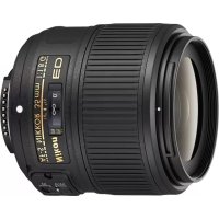
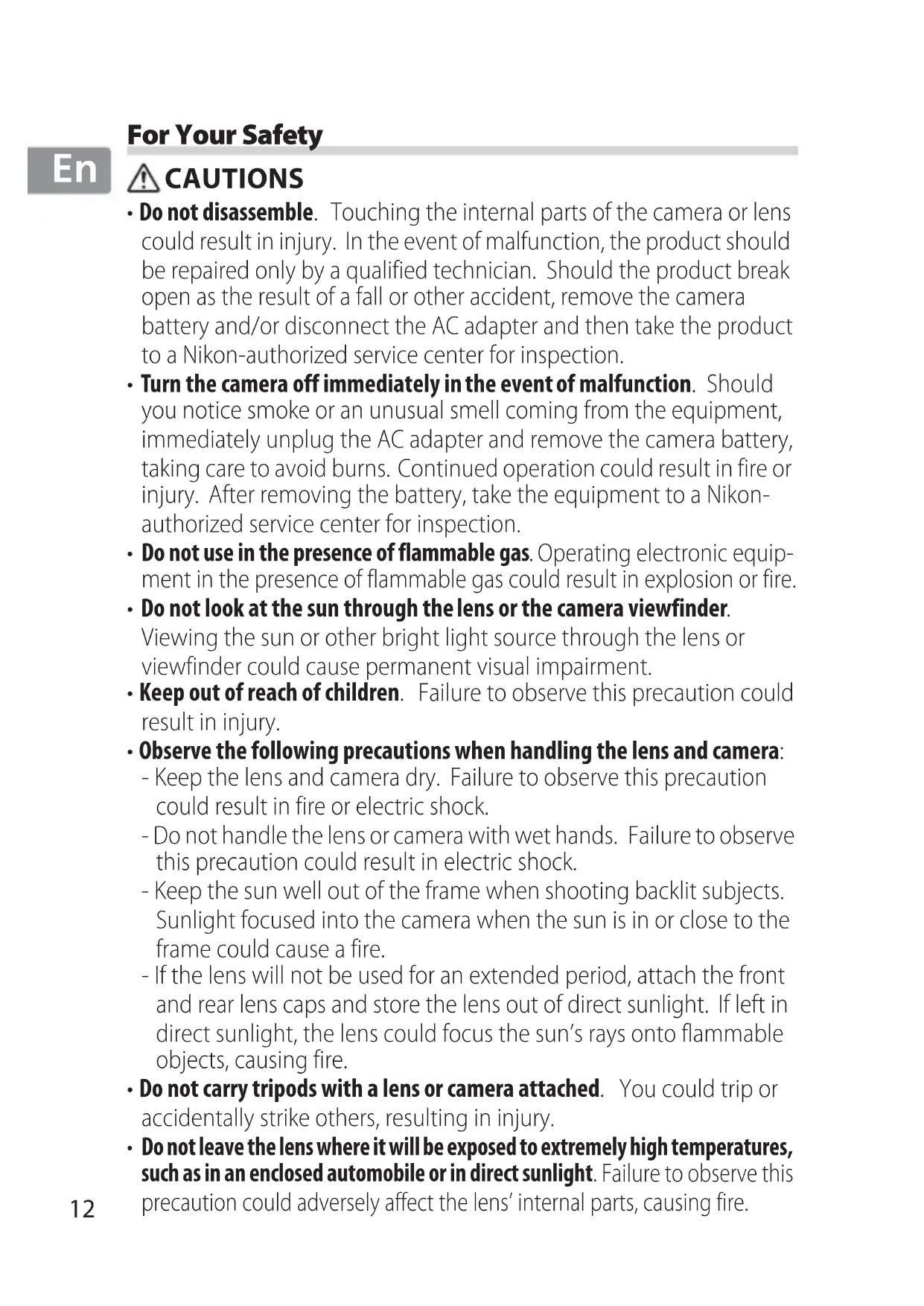
Thank you for your purchase of an AF-S NIKKOR 50mm f/1.8G lens. Before using this product, please carefully read both these instructions and the camera manual.
Note: When mounted on a DX-format digital single-lens reflex camera such as the D7000 or cameras in the D300 series, this lens has an angle of view of 31^ 30' and a focal length equivalent to 75 mm (35 mm format).
■Parts of the Lens
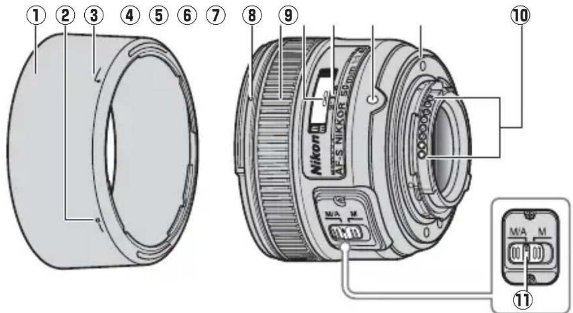
① Lens hood...... 16
② Lens hood lock mark...... 16
③ Lens hood alignment mark.... 16
④ Lens hood mounting mark.... 16
⑤ Focus ring.... 15
⑥ Focus distance indicator...16
⑦ Focus distance mark .....16
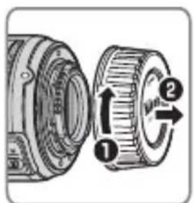
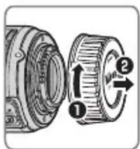
⑧ Lens mounting mark
⑨ Rubber lens-mount gasket......18
⑩ CPU contacts ....18
⑪ Focus-mode switch......15
En
■Compatibility
Check marks ("√") indicate supported features, dashes ("—") features that are not supported. Some limitations may apply; see the camera manual for details.
| Camera | Exposure (Shooting) mode | AF^5 | |||
| P4 | S A | M | |||
| Nikon FX-format and DX-format digital single-lens reflex cameras | √ | √ | √ | √ | √ |
| F6, F5, F100, F/N80-series1, F/N75-series1, F/N65-series1,Pronea 600i/6i1,Pronea S2 | √ | √ | √ | √ | √ |
| F4-series, F90X/N90s1, F90-series/N901, F70-series/N701 | √ | √ | — | — | √ |
| F60-series/N601, F/N55-series1, F50-series/N501,F-401x/N50051, F-401s/N4004s1, F-401/N40041 | √ | √ | √ | √ | — |
| F-801s/N8008s1, F-801/N80081, F-601M/N60001 | √ | √ | — | — | — |
| F3AF, F-601/N60061, F-501/N20203, Nikon manual focus cameras (excluding F-601M/N60001) | — | ||||
1 N-series cameras and Pronea 6i sold in U.S.A. only.
2 Exposure mode M (manual) not available.
3 N2020 sold in U.S.A. and Canada only.
4 Includes AUTO and scene (Digital Vari-Program) modes.
5 Autofocus.
Focus
Supported focus modes are shown in the following table (for information on camera focus modes, see the camera manual).
En
| Camera | Camera focus mode | Lens focus mode | |
| M/AM | |||
| Nikon FX-format and DX-format digital single-lens reflex cameras, F6, F5, F4-series, F100, F90X/N90s*, F90-series/N90*, F/N80-series*, F/N75-series*, F70-series/N70*, F/N65-series*, Pronea 600i/6i*, Pronea S | AF | Autofocus with manual override | Manual focus with electronic rangefinder |
| MF | Manual focus (electronic rangefinder available with all cameras except F-601M/N6000*) | ||
| F60-series/N60*, F/N55-series*, F50-series/N50*, F-801s/N8008s*, F-801/N8008*, F-601M/N6000*, F-401x/N5005*, F-401s/N4004s*, F-401/N4004* | AF, MF | ||
*N-series cameras and Pronea 6i sold in U.S.A. only.
M/A (Autofocus with Manual Override)
To focus using autofocus with manual override (M/A):
1 Slide the lens focus-mode switch to M/A.
2 Focus.
If desired, autofocus can be over-ridden by rotating the lens focus ring while the shutter-release button is pressed halfway (or, if the camera is equipped with an AF-ON button, while the AF-ON button is pressed). To refocus using autofocus, press the shutter-release button halfway or press the AF-ON button again.
En
■Depth of Field
The depth-of-field indicators on the lens show the approximate depth of field (see page 172 for more information). If the camera offers depth-of-field preview (stop down), depth of field can also be previewed in the viewfinder.

Aperture
Aperture is adjusted using camera controls.
■Built-in Flash Units
When using the built-in flash on cameras equipped with a built-in flash unit, shoot at ranges of 0.6 m (2 ft) or more and remove the lens hood to prevent vignetting (shadows created where the end of the lens obscures the built-in flash).
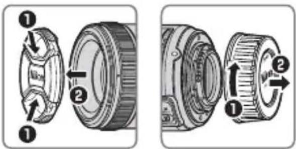
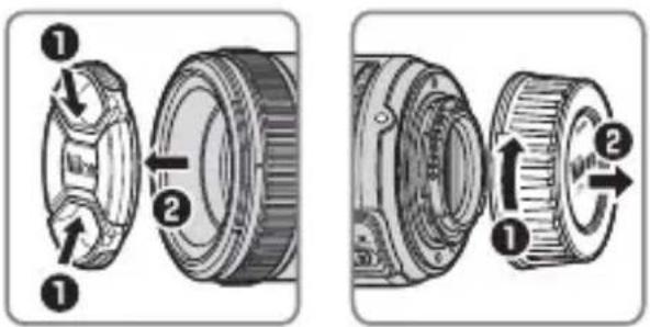
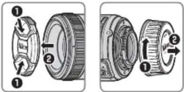
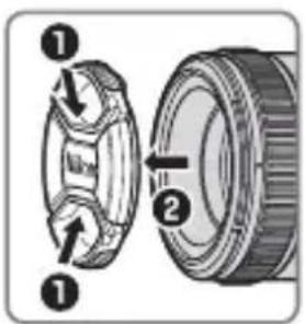
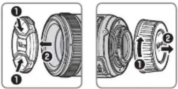
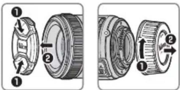
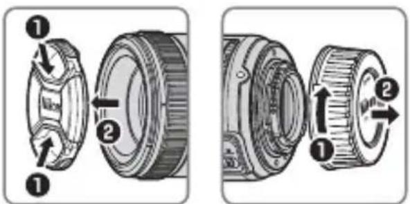
The Lens Hood
The lens hoods protect the lens and block stray light that would otherwise cause flare or ghosting.

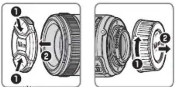
Align the lens hood lock mark (—○) with the lens hood mounting mark (●) on the lens (③).
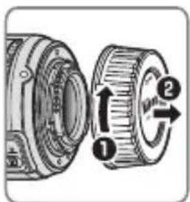
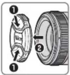
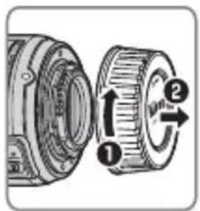
When attaching or removing the hood, hold it near the symbol on its base and avoid gripping it too tightly.
Vignetting may occur if the hood is not correctly attached.
The hood can be reversed and mounted on the lens when not in use. When the hood is reversed, it can be attached and removed by rotating it while holding it near the lock mark (—○).
■Focusing Screens
The following cameras support a variety of focusing screens for use in different situations.
En
| ScreenCamera | A B C E | EC-BEC-E | G1 | G2 | G3 | G4 | J | L | M | U | |||
| F6 | ◎ | ◎ | — | ◎ | — | — | — | — | — | ◎ | ◎ | ◎ | |
| F5+DP-30 | ◎ | ◎ | ◎ | ◎ | ◎ | ◎ | ◎ | ◎ | |||||
| F5+DA-30 | ◎ | ◎ | ◎ | ◎ | ◎(+0.5) | ◎ | ◎ | ◎ | |||||
◎: Recommended.
O: Vignetting visible in viewfinder (photographs are not affected).
—: Not compatible with camera.
(:): Figures in parentheses give the exposure compensation for center-weighted metering. Select "Other screen" for Custom Setting b6 ("Screen comp.") when adjusting exposure compensation for the F6; note that with screens other than B or E, "Other screen" must be selected even when the value for exposure compensation is 0. Exposure compensation for the F5 can be adjusted using Custom Setting 18; see the camera manual for details.
Empty cell: Not suited to use with this lens. Note that type M screens can however be used for photomicrography and macro photography at magnifications of 1 : 1 or higher.
Note: The F5 supports matrix metering with A, B, E, EC-B/EC-E, J, and L focusing screens only.
En
Lens Care
- Do not pick up or hold the lens or camera using only the lens hood.
- Keep the CPU contacts clean.
- Should the rubber lens-mount gasket be damaged, cease use immediately and take the lens to a Nikon-authorized service center for repair.
- Use a blower to remove dust and lint from the lens surfaces. To remove smudges and fingerprints, apply a small amount of ethanol or lens cleaner to a soft, clean cotton cloth or lens-cleaning tissue and clean from the center outwards using a circular motion, taking care not to leave smears or touch the glass with your fingers.
- Never use organic solvents such as paint thinner or benzene to clean the lens.
- The lens hood or NC filters can be used to protect the front lens element.
- Attach the front and rear caps before placing the lens in its flexible pouch.
- If the lens will not be used for an extended period, store it in a cool, dry location to prevent mold and rust. Do not store in direct sunlight or with naphtha or camphor moth balls.
- Keep the lens dry. Rusting of the internal mechanism can cause irreparable damage.
• Leaving the lens in extremely hot locations could damage or warp parts made from reinforced plastic.
■Supplied Accessories
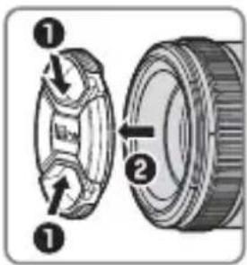
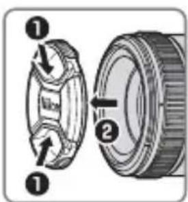
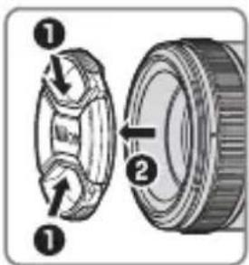
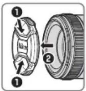
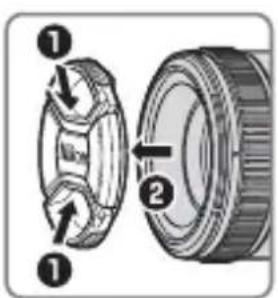
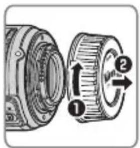
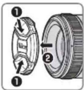
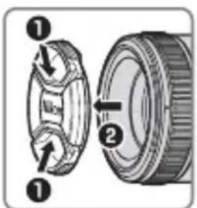
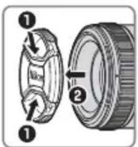
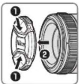
- 58 mm snap-on Front Lens Cap LC-58
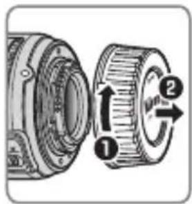
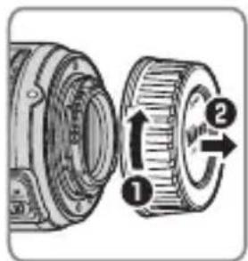
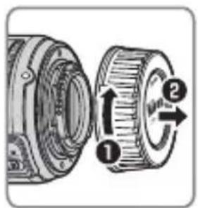
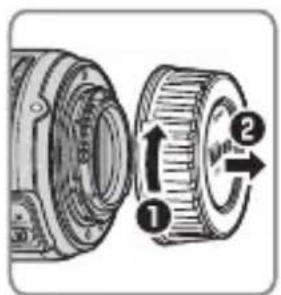
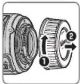
- Rear Lens Cap LF-4
• Bayonet Hood HB-47 - Flexible Lens Pouch CL-1013
■Compatible Accessories
- 58 mm screw-on filters
Specifications
| Type Type G AF-S lens with built-in CPU and F mount | |
| Focal length 50 mm | |
| Maximum aperture f/1.8 | |
| Lens construction | 7 elements in 6 groups (including 1 aspherical lens element) |
| Angle of view | Nikon film SLR and FX-format D-SLR cameras: 47°Nikon DX-format D-SLR cameras: 31° 30'IX240 system cameras: 38° |
| Distance information Output to camera | |
| Focusing Autofocus controlled by Silent Wave Motor and separate focus ring for manual focus | |
| Focus distance indicator | Graduated in meters from 0.45 m to infinity (∞) |
| Minimum focus distance | 0.45 m (1.48 ft) from focal plane |
| Diaphragm blades 7 (rounded diaphragm opening) | |
| Diaphragm Fully automatic | |
| Aperture range | f/1.8 to f/16 |
| Metering | Full aperture |
| Filter-attachment size | 58 mm (P=0.75 mm) |
| Dimensions | Approx. 72 mm diameter × 52.5 mm (distance from camera lens mount flange) |
| Weight | Approx. 185 g (6.6 oz) |
Nikon reserves the right to change the specifications of the hardware described in this manual at any time and without prior notice.
Für Ihre Sicherheit
De

SICHERHEITSHINWEISE
| Scheibe | A B C E | EC-BEC-E G1 G2 G3 G4 J L M UKamera | |||||||||||
| F6 | ◎ | ◎ | — | ◎ | — | — | — | — | — | ◎ | ◎ | ◎ | |
| F5+DP-30 | ◎ | ◎ | ◎ | ◎ | ◎ | ◎ | ◎ | ◎ | |||||
| F5+DA-30 | ◎ | ◎ | ◎ | ◎ | (+0,5) | ◎ | ◎ | ◎ | |||||
| Appareil photo\Verre | A B C E | EC-B EC-E G1 G2 | G3 G4 J L | M U | |||||||||
| F6 | ◎ | ◎ | — | ◎ | — | — | — | — | — | ◎ | ◎ | ◎ | |
| F5+DP-30 | ◎ | ◎ | ◎ | ◎ | ◎ | ◎ | ◎ | ◎ | |||||
| F5+DA-30 ◎ | ◎ | ◎ | ◎ | (+0,5) | ◎ | ◎ | ◎ | ||||||
| Skiva | A B C E | EC-B EC-E | G1 G2 G3 G4 | J L M | UKamera | ||||||||
| F6 | ◎ | ◎ | — | ◎ | — | — | — | — | ◎ | ◎ | ◎ | ||
| F5+DP-30 | ◎ | ◎ | ◎ | ◎ | ◎ | ◎ | ◎ | ◎ | |||||
| F5+DA-30 | ◎ | ◎ | ◎ | ◎ | (+0.5) | ◎ | ◎ | ◎ | |||||

① Pára-sol da objectiva....72
Alinhe a marca de bloqueio do pára-sol da objectiva (—○) com a marca de montagem do pára-sol da objectiva (●) na objectiva (3).
Pt
| Ecrã | A B C E | EC-B EC-E | G1 G2 G3 G4 | J L M | UCâmara | ||||||||
| F6 | ◎ | ◎ | — | ◎ | — | — | — | — | ◎ | ◎ | ◎ | ||
| F5+DP-30 | ◎ | ◎ | ◎ | ◎ | ◎ | ◎ | ◎ | ◎ | |||||
| F5+DA-30 | ◎ | ◎ | ◎ | ◎ | (+0,5) | ◎ | ◎ | ◎ | |||||
| Tela | A B C E | EC-B EC-E | G1 G2 G3 G4 | J L M | UCâmera | |||||||
| F6 | ◎ | ◎ | — | ◎ | — | — | — | — | ◎ | ◎ | ◎ | |
| F5+DP-30 | ◎ | ◎ | ◎ | ◎ | ◎ | ◎ | ◎ | ◎ | ||||
| F5+DA-30 | ◎ | ◎ | ◎ | ◎ | (+0,5) | ◎ | ◎ | ◎ | ||||
| Schermo | A B C E | EC-BEC-E G1 G2 | G3 G4 J L M U | Fotocamera | |||||||||
| F6 | ◎ | ◎ | — | ◎ | — | — | — | — | — | ◎ | ◎ | ◎ | |
| F5+DP-30 | ◎ | ◎ | ◎ | ◎ | ◎ | ◎ | ◎ | ◎ | |||||
| F5+DA-30 | ◎ | ◎ | ◎ | ◎ | (+0.5) | ◎ | ◎ | ◎ | |||||
① Parasolar obiectiv......120
② Marcaj fixare parasolar
obiectiv....120
③ Marcaj aliniere parasolar
obiectiv......120
④ Marcaj montare parasolar
obiectiv......120
⑤ Inel de focalizare .....119
⑥ Indicator distanță focală......119
| 照相机\对焦屏 | A | B | C | E | EC-B | EC-E | G1 | G2 | G3 | G4 | J | L | M | U | |
| F6 | ◎ | ◎ | — | ◎ | — | — | — | — | — | — | — | ◎ | ◎ | ◎ | |
| F5+DP-30 | ◎ | ◎ | ◎ | ◎ | ◎ | ◎ | ◎ | ◎ | |||||||
| F5+DA-30 | ◎ | ◎ | ◎ | ◎ | (+0.5) | ◎ | ◎ | ◎ |
◎: 推荐使用。
光
將遮罩鎖定標記 (—〇)與鏡頭上的遮
光罩接環標記()對齊(3)。
光
| 屏幕相機 | A | B | C | E | EC-BEC-E | G1 | G2 | G3 | G4 | J | L | M | U | ||||
| F6 | ◎ | ◎ | — | ◎ | — | — | — | — | — | ◎ | — | ◎ | ◎ | ||||
| F5+DP-30 | ◎ | ◎ | ◎ | ◎ | ◎ | ◎ | ◎ | ◎ | |||||||||
| F5+DA-30 | ◎ | ◎ | ◎ | ◎ | ◎(+0.5) | ◎ | ◎ | ◎ |
◎:建議使用。
| 카메라\스크린 | A | B | C | EC-BEEC-E | G1 | G2 | G3 | G4 | J | L | M | U | |
| F6 | ◎ | ◎ | — | ◎ | — | — | — | — | — | ◎ | ◎ | ◎ | |
| F5+DP-30 | ◎ | ◎ | ◎ | ◎ | ◎ | ◎ | ◎ | ◎ | |||||
| F5+DA-30 | ◎ | ◎ | ◎ | ◎ | ◎(+0.5) | ◎ | ◎ | ◎ |
◎:권 장 .
①Tudung lensa 168
②Tanda kunci tudung lensa .... 168
③Tanda kesejajaran tudung
lensa 168
④Tanda pemasangan tudung
lensa.... 168
⑤Cincin fokus.... 167
⑥Indikator jarak fokus...... 167
⑦Tanda jarak fokus....167
⑧Tanda pemasangan lensa
⑨Gasket karet pemasangan lensa ....170
⑩Kontak CPU....170
⑪Switch mode fokus......167
Kompatibilitas
Sejajarkan tanda kunci tudung lensa (—○) dengan tanda pemasangan tudung lensa (●) pada lensa (3).
| Layar | A B C E | EC-B EC-E | G1 G2 G3 G4 | J L M | UKamera | |||||||
| F6 | ◎ | ◎ | — | ◎ | — | — | — | — | ◎ | ◎ | ◎ | |
| F5+DP-30 | ◎ | ◎ | ◎ | ◎ | ◎ | ◎ | ◎ | ◎ | ||||
| F5+DA-30 | ◎ | ◎ | ◎ | ◎ | (+0,5) | ◎ | ◎ | ◎ | ||||
Depth of field (Imperial)
(ft)
| Focus distance | Depth of field | Reproduction ratio | |||||||
| f/1.8 | f/2 | f/2.8 | f/4 | f/5.6 | f/8 | f/11 | f/16 | ||
| 1.75 | 1 ft 8 12/16 in.—1 ft 9 4/16 in. | 1 ft 8 12/16 in.—1 ft 9 4/16 in. | 1 ft 8 12/16 in.—1 ft 9 4/16 in. | 1 ft 8 10/16 in.—1 ft 9 6/16 in. | 1 ft 8 6/16 in.—1 ft 9 10/16 in. | 1 ft 8 4/16 in.—1 ft 9 13/16 in. | 1 ft 7 15/16 in.—1 ft 10 3/16 in. | 1 ft 7 9/16 in.—1 ft 10 13/16 in. | |
| 2.5 | 2 ft 5 10/16 in.—2 ft 6 8/16 in. | 2 ft 5 8/16 in.—2 ft 6 8/16 in. | 2 ft 5 6/16 in.—2 ft 6 12/16 in. | 2 ft 5 3/16 in.—2 ft 6 15/16 in. | 2 ft 4 13/16 in.—2 ft 7 5/16 in. | 2 ft 4 5/16 in.—2 ft 8 1/16 in. | 2 ft 3 12/16 in.—2 ft 8 12/16 in. | 2 ft 2 12/16 in.—2 ft 10 5/16 in. | |
| 4 | 3 ft 10 13/16 in.—4 ft 1 3/16 in. | 3 ft 10 13/16 in.—4 ft 1 5/16 in. | 3 ft 10 5/16 in.—4 ft 1 15/16 in. | 3 ft 9 10/16 in.—4 ft 2 12/16 in. | 3 ft 8 10/16 in.—4 ft 3 15/16 in. | 3 ft 7 7/16 in.—4 ft 5 14/16 in. | 3 ft 5 14/16 in.—4 ft 8 6/16 in. | 3 ft 3 10/16 in.—5 ft 1 7/16 in. | |
| 7 | 6 ft 8 4/16 in.—7 ft 4 1/16 in. | 6 ft 8 1/16 in.—7 ft 4 7/16 in. | 6 ft 6 10/16 in.—7 ft 6 6/16 in. | 6 ft 4 7/16 in.—7 ft 9 6/16 in. | 6 ft 1 13/16 in.—8 ft 1 11/16 in. | 5 ft 10 3/16 in.—8 ft 9 2/16 in. | 5 ft 6 2/16 in.—9 ft 8 3/16 in. | 5 ft 8/16 in.—11 ft 9 6/16 in. | |
| ∞ | 142 ft 1 3/16 in.—∞ | 131 ft 5 10/16in.—∞ | 94 ft—∞ | 65 ft 10 13/16in.—∞ | 47 ft 1 15/16 in.—∞ | 33 ft 1 5/16 in.—∞ | 24 ft 2 1/16 in.—∞ | 16 ft 8 10/16 in.—∞ | |
En
■Notices for Customers in Europe
This symbol indicates that electrical and electronic equipment is to be collected separately.
The following apply only to users in European countries:
- This product is designated for separate collection at an appropriate collection point. Do not dispose of as household waste.
- Separate collection and recycling helps conserve natural resources and prevent negative consequences for human health and the environment that might result from incorrect disposal.
- For more information, contact the retailer or the local authorities in charge of waste management.
De
No reproduction in any form of this manual, in whole or in part (except for brief quotation in critical articles or reviews), may be made without written authorization from NIKON CORPORATION.