
SA60M - Receiver ALPINE - Free user manual and instructions
Find the device manual for free SA60M ALPINE in PDF.

| Product type | Mono subwoofer amplifier |
| Brand | Alpine |
| Model | SA60M |
| Dimensions (W x H x D) | 204 x 57.5 x 204 mm |
| Weight | 2.2 kg |
| Power supply voltage | 12 V DC (negative ground) |
| Output power (4 Ω) | 330 W RMS x 1 |
| Output power (2 Ω) | 600 W RMS x 1 |
| Frequency response | 10 Hz - 400 Hz (+0/-3 dB) |
| Low-pass filter (LPF) | 50 Hz - 400 Hz, 24 dB/octave slope |
| Bass EQ | 50 Hz, adjustable 0 to +12 dB |
| Input sensitivity (RCA) | High: 0.5 - 10 V / Low: 0.2 - 4 V |
| Input impedance | > 10 kΩ |
| Preamp output | Pass-Through CH-1/2, 4 V max. |
| Protection | Thermal, short circuit, over/under voltage (LED indicator) |
| Fuse | 30 A x 2 |
| Max current consumption | 60 A (with corresponding external fuse) |
| Supplied accessories | 4 self-tapping screws M4 x 20, 1 hex key |
| Compliance | FCC Class B |
| Installation | Only on 12 V vehicle with negative ground |
Frequently Asked Questions - SA60M ALPINE
User questions about SA60M ALPINE
0 question about this device. Answer the ones you know or ask your own.
Ask a new question about this device
Download the instructions for your Receiver in PDF format for free! Find your manual SA60M - ALPINE and take your electronic device back in hand. On this page are published all the documents necessary for the use of your device. SA60M by ALPINE.
USER MANUAL SA60M ALPINE
FOR CAR USE ONLY/POUR APPLICATION AUTOMOBILE/PARA USO EN AUTOMÓVILES
ALPINE®
S-A60M
MONO POWER AMPLIFIER
S-A32F
4 CHANNEL POWER AMPLIFIER
S-A55V
4 CHANNEL + MONO POWER AMPLIFIER
- OWNER'S MANUAL
Please read before using this equipment.
• MODE D'EMPLOI
Victoria 3803, Australia
Phone 03-8787-1200
ALPINE ELECTRONICS GmbH
Ohmstraße 4
Fletchamstead Highway, Coventry CV4 9TW, U.K.
www.alpine.co.uk
ALPINE ELECTRONICS FRANCE S.A.R.L.
Designed by ALPINE Japan
Printed in Korea
68-35792Z59-A(Y-A5)
M3514659010
English
CONTENTS
WARNING....1
SERVICE CARE 2
ACCESSORIES....3
INSTALLATION....3
CONNECTIONS 4
CONNECTION CHECK LIST 8
SWITCH SETTINGS 9
SYSTEM DIAGRAMS 12
SPECIFICATIONS....20
WARNING
Points to Observe for Safe Usage
Read this manual carefully before using the system components. They contain instructions on how to use this product in a safe and effective manner. Alpine cannot be responsible for problems resulting from failure to observe the instructions in this manual.
WARNING
This symbol means important instructions. Failure to heed them can result in serious injury or death.
DO NOT OPERATE ANY FUNCTION THAT TAKES YOUR ATTENTION AWAY FROM SAFELY DRIVING YOUR VEHICLE.
Any function that requires your prolonged attention should only be performed after coming to a complete stop. Always stop the vehicle in a safe location before performing these functions. Failure to do so may result in an accident.
KEEP THE VOLUME AT A LEVEL WHERE YOU CAN STILL HEAR OUTSIDE NOISES WHILE DRIVING.
Excessive volume levels that obscure sounds such as emergency vehicle sirens or road warning signals (train crossings, etc.) can be dangerous and may result in an accident. LISTENING AT LOUD VOLUME LEVELS IN A CAR MAY ALSO CAUSE HEARING DAMAGE.
DO NOT DISASSEMBLE OR ALTER.
Doing so may result in an accident, fire or electric shock.
USE THIS PRODUCT FOR MOBILE 12V APPLICATIONS.
Use for other than its designed application may result in fire, electric shock or other injury.
USE THE CORRECT AMPERE RATING WHEN REPLACING FUSES.
Failure to do so may result in fire or electric shock.
DO NOT BLOCK VENTS OR RADIATOR PANELS.
Doing so may cause heat to build up inside and may result in fire.
MAKE THE CORRECT CONNECTIONS.
Failure to make the proper connections may result in fire or product damage.
USE ONLY IN CARS WITH A 12 VOLT NEGATIVE GROUND.
(Check with your dealer if you are not sure.) Failure to do so may result in fire, etc.
BEFORE WIRING, DISCONNECT THE CABLE FROM THE NEGATIVE BATTERY TERMINAL.
Failure to do so may result in electric shock or injury due to electrical shorts.
DO NOT ALLOW CABLES TO BECOME ENTANGLED IN SURROUNDING OBJECTS.
Arrange wiring and cables in compliance with the manual to prevent obstructions when driving. Cables or wiring that obstruct or hang up on places such as the steering wheel, gear lever, brake pedals, etc. can be extremely hazardous.
DO NOT SPLICE INTO ELECTRICAL CABLES.
Never cut away cable insulation to supply power to other equipment. Doing so will exceed the current carrying capacity of the wire and result in fire or electric shock.
DO NOT DAMAGE PIPE OR WIRING WHEN DRILLING HOLES.
When drilling holes in the chassis for installation, take precautions so as not to contact, damage or obstruct pipes, fuel lines, tanks or electrical wiring. Failure to take such precautions may result in fire.
DO NOT USE BOLTS OR NUTS IN THE BRAKE OR STEERING SYSTEMS TO MAKE GROUND CONNECTIONS.
Bolts or nuts used for the brake or steering systems (or any other safety-related system), or tanks should NEVER be used for installations or ground connections. Using such parts could disable control of the vehicle and cause fire etc.
KEEP SMALL OBJECTS SUCH AS BATTERIES OUT OF THE REACH OF CHILDREN.
Swallowing them may result in serious injury. If swallowed, consult a physician immediately.
CAUTION
This symbol means important instructions. Failure to heed them can result in injury or property damages.
HALT USE IMMEDIATELY IF A PROBLEM APPEARS.
Failure to do so may cause personal injury or damage to the product. Return it to your authorized Alpine dealer or the nearest Alpine Service Center for repairing.
HAVE THE WIRING AND INSTALLATION DONE BY EXPERTS.
The wiring and installation of this unit requires special technical skill and experience. To ensure safety, always contact the dealer where you purchased this product to have the work done.
USE SPECIFIED ACCESSORY PARTS AND INSTALL THEM SECURELY.
Be sure to use only the specified accessory parts. Use of other than designated parts may damage this unit internally or may not securely install the unit in place. This may cause parts to become loose resulting in hazards or product failure.
ARRANGE THE WIRING SO IT IS NOT CRIMPED OR PINCHED BY A SHARP METAL EDGE.
Route the cables and wiring away from moving parts (like the seat rails) or sharp or pointed edges. This will prevent crimping and damage to the wiring. If wiring passes through a hole in metal, use a rubber grommet to prevent the wire's insulation from being cut by the metal edge of the hole.
DO NOT INSTALL IN LOCATIONS WITH HIGH MOISTURE OR DUST.
Avoid installing the unit in locations with high incidence of moisture or dust. Moisture or dust that penetrates into this unit may result in product failure.
SERVICE CARE
♦ IMPORTANT NOTICE
This Amplifier has been type tested and found to comply with the limits for a Class B computing device in accordance with the specifications in Subpart J of Part 15 of FCC Rules. This equipment generates and uses radio frequency energy, and it must be installed and used properly in accordance with the manufacturer's instructions.
SERIAL NUMBER:
INSTALLATION DATE:
INSTALLATION TECHNICIAN:
PLACE OF PURCHASE:
IMPORTANT
Please record the serial number of your unit in the space provided here and keep it as a permanent record. The serial number plate is located on the rear of the unit.
◆ For European Customers
Should you have any questions about warranty, please consult your store of purchase.
◆ For Customers in other Countries
IMPORTANT NOTICE
Customers who purchase the product with which this notice is packaged, and who make this purchase in countries other than the United States of America and Canada, please contact your dealer for information regarding warranty coverage.
ACO
- Self-Ta
- Hexag
INS
Due to the S-A60M produce this reason, location such as i location: dealer.
-
Using screw
-
Make surfa drilli r
-
Drill
-
Positi screw screw
Self- M4 :

ACCESSORIES
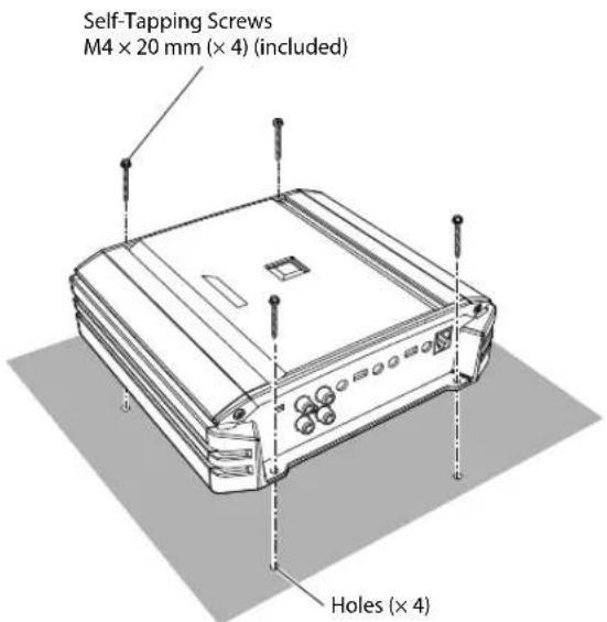
- Self-Tapping Screw (M4 × 20) ....4
• Hexagon Wrench ....1
INSTALLATION
Due to the high power output of the S-A60M/S-A32F/S-A55V considerable heat is produced when the amplifier is in operation. For this reason, the amplifier should be mounted in a location which will allow for free circulation of air, such as inside the trunk. For alternate installation locations, please contact your authorized Alpine dealer.
- Using the amplifier as a template, mark the four screw locations.
- Make sure there are no objects behind the surface that may become damaged during drilling.
- Drill the screw holes.
- Position the S-A60M/S-A32F/S-A55V over the screw holes, and secure with four self-tapping screws.
(e.g. S-A32F)
CONNECTIONS
Before making connections, be sure to turn the power off to all audio components.
S-A60M
S-A32F
4-EN
S-A55V
*1 For details on the wires size to be used, refer to the supplied "Cautions on Power Supply Wires Connection" and "Cautions on Power Supply Wires" (page 19), and then use the wire of the specified size.
*2 Be sure to add an External Fuse (e.g. Fuse Block, Circuit Breaker) with the battery lead as close as possible to the battery's positive (+) terminal. Add an external fuse with the same capacity, or a slightly larger capacity, as the sum total of the fuse capacities of the amplifier.
For details on the fuse capacity of this machine, see "Battery Lead (4)" (page 6).
*3 Connect all equipment to the same ground point while keeping wire length as short as possible.
*4 To securely connect the ground lead, use an already installed screw.
To prevent external noise from entering the audio system
- Locate the unit and route the leads at least 10 cm (4") away from the vehicle's harness.
- Keep the battery power leads as far away from other leads as possible.
- Connect the ground lead securely to a bare metal spot (remove any paint or grease if necessary) of the vehicle's chassis.
- If you add an optional noise suppressor, connect it as far away from the unit as possible. Your Alpine dealer carries various noise suppressors, contact them for further information.
- Your Alpine dealer knows best about noise prevention measures so consult your dealer for further information.
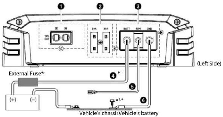
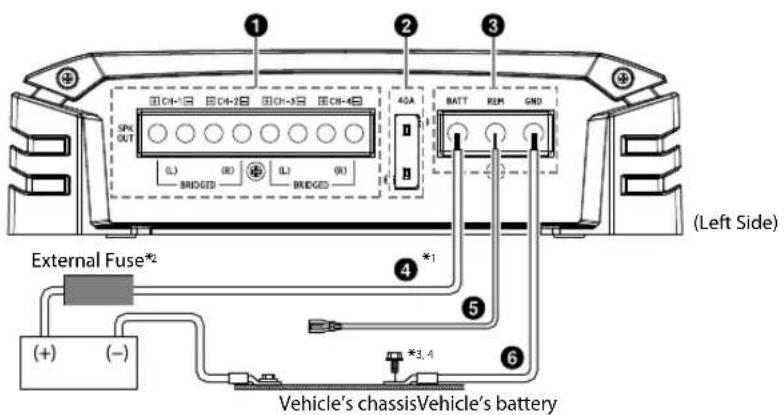
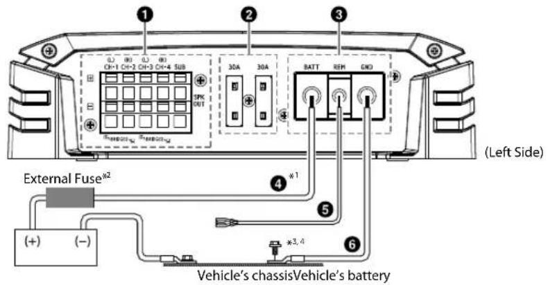
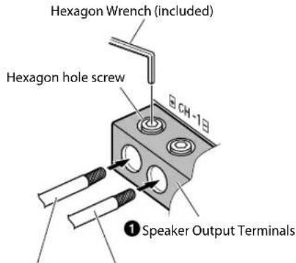
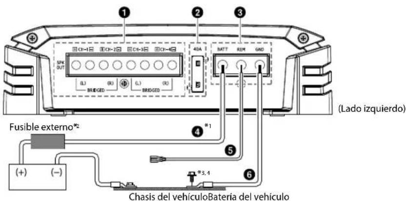
① Speaker Output Terminals
Connect the Speaker Output Lead (+) / (−) using the Hexagon hole screw of the Speaker Output Terminals ①
- For details on how to connect, see "Cautions on wire lead connections" (page 7). Be sure to observe correct speaker output connections and polarity in relation to the other speakers in the system. Connect the positive output to the positive speaker terminal and the negative to negative.
About Subwoofer Input/Output (S-A60M/S-A55V only)
- The input is stereo but the output is monaural.
- Reversing subwoofer polarity (swapping positive and negative connections to the subwoofer) may be desirable in some installations for optimum bass performance.
About Bridged Connections (S-A32F/S-A55V only)
In the bridged mode, connect the left positive to the positive terminal of the speaker and the right negative to the negative terminal of the speaker. Do not use the speaker (−) terminals as a common lead between the left and right channels.
NOTE:
- Do not connect the speaker (−) terminal to the vehicle's chassis.
② Fuse
S-A60M/S-A55V 30 A × 2 S-A32F 40 A
USE THE CORRECT AMPERE RATING WHEN REPLACING FUSES.
Failure to do so may result in fire or electric shock.
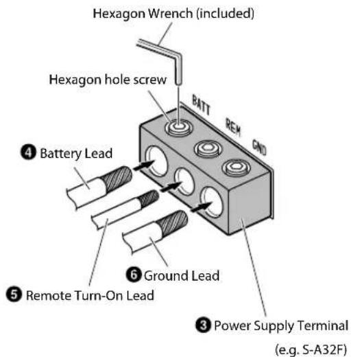
③ Power Supply Terminal
Connect the Battery Lead (4) Remote Turn-on Lead (5) and Ground Lead ( ) 6ing the Hexagon hole screw of the Power Supply Terminal (3)
- For details on how to connect, see "Cautions on wire lead connections" (page 7).
④ Battery Lead (sold separately)
Be sure to add an External Fuse (e.g. Fuse Block, Circuit Breaker) with the battery lead as close as possible to the battery's positive (+) terminal. This fuse will protect your vehicle's electrical system in case of a short circuit. See below for appropriate fuse value requirement: S-A60M/S-A55V ....60 amp fuse S-A32F ....40 amp fuse
- For details on the wires size to be used, refer to the supplied "Cautions on Power Supply Wires Connection" and "Cautions on Power Supply Wires" (page 19), and then use the wire of the specified size.
⑤ Remote Turn-On Lead (sold separately)
Connect this lead to the remote turn-on (positive trigger, (+) 12 V only) lead of your head unit. If a remote turn-on lead is not available, see "CONNECTION CHECK LIST" section on page 8 for alternative method.
- When connecting the speaker output leads of the head unit to this unit with a Speaker-RCA Conversion cable (sold separately), you do not need to connect the remote turn-on lead, owing to the "REMOTE SENSING" function of this unit. However, the "REMOTE SENSING" function may not work depending on the signal source connected. In such a case, connect the remote turn-on lead to an incoming power supply cord (accessory power) in the ACC position.
⑥ Ground Lead (sold separately)
Connect this lead securely to a clean, bare metal spot on the vehicle's chassis. Verify this point to be a true ground by checking for continuity between that point and the negative (−) terminal of the vehicle's battery. Ground all your audio components to the same point on the chassis to prevent ground loops while keeping wire length as short as possible.
- For details on the wires size to be used, refer to the supplied "Cautions on Power Supply Wires Connection" and "Cautions on Power Supply Wires" (page 19), and then use the wire of the specified size.
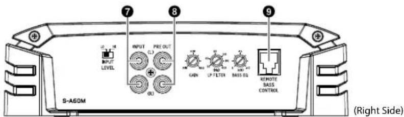
⑦ RCA Input Jacks
Connect these jacks to the line out leads on your head unit using RCA extension cables or Speaker-RCA Conversion cable (sold separately). Be sure to observe correct channel connections; Left to Left and Right to Right.
8 Pre-Out Jacks (S-A60M only)
These jacks provide a line level output. This is an ideal output for driving a second subwoofer amp. This output is full-range, and is not affected by the crossover.
⑨ Remote Bass Control (optional)
Connect the Remote Bass Control Unit RUX-KNOB.2 (sold separately) to adjust the output level remotely. This is not to replace appropriate gain level setting between the amplifier and head unit.
Cautio
When us wire), us connect properp make thi
- Check
- For the Con Wire the - If th dea
- Remo leads

Tw
NOTES:
- If length connects or sour - On the electric
- Tight hexag
Befor shrin exten
Power S
He
4 Batt
5 Remo
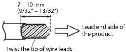
Cautions on wire lead connections
When using third-party wire cables (power supply wire), use the supplied screws to simplify the connection. Refer to the description below for the proper procedure. If you are in doubt about how to make this connection, consult your dealer.
- Check the wire size.
- For details on the wires size to be used, refer to the supplied "Cautions on Power Supply Wires Connection" and "Cautions on Power Supply Wires" (page 19), and then use the wire of the specified size. - If the wire gauge used is unknown, ask your dealer.
- Remove the insulation from the ends of the wire leads by about 7 - 10 mm (9/32" - 13/32").
NOTES:
- If length of the exposed wire is too short, a poor connection may occur causing operation failure or sound interruption.
-
On the other hand, if the length is too long, an electrical short-circuit may occur.
-
Tighten the hexagon hole screw with the hexagon wrench (included) to secure the lead.
Before making this connection, use insulated shrink tubing to cover any exposed wire extending beyond the terminal.
Power Supply Terminal
Speaker Output Terminals
Speaker Output Lead (+) Speaker Output Lead (−) (e.g. S-A32F)
NOTES:
- Be sure to use the Hexagon hole screw attached to the Power Supply Terminal (3) or Speaker Output Terminals (1)
- For safety reasons, connect the battery leads last.
• To prevent disconnection of the leads or dropping of the unit, do not use the cabling to carry the unit.
CONNECTION CHECK LIST
Please check your head unit for the conditions listed below:
Remote Turn-On Lead
a. The head unit does not have a remote turn-on or power antenna lead.
b. The head unit's power antenna lead is activated only when the radio is on (turns off in the tape or CD Mode).
c. The head unit's power antenna lead is logic level output (+) 5 V, negative trigger (grounding type), or cannot sustain (+) 12 V when connected to other equipment in addition to the vehicle's power antenna.
If any of the above conditions exist, the remote turn-on lead of your S-A60M/S-A32F/S-A55V must be connected to a switched power source (ignition) in the vehicle. Be sure to use a 3 A fuse as close as possible to this ignition tap. Using this connection method, the S-A60M/S-A32F/S-A55V will turn on and stay on as long as the ignition switch is on.
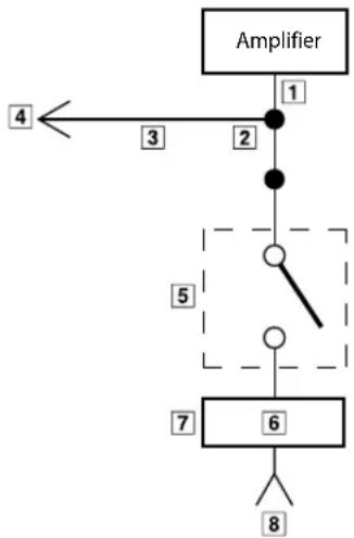
If this is objectionable, a SPST (Single Pole, Single Throw) switch, in addition to the 3 A fuse mentioned above, may be installed in-line on the S-A60M/S-A32F/S-A55V turn-on lead. This switch will then be used to turn on (and off) the S-A60M/S-A32F/S-A55V. Therefore, the switch should be mounted so that is accessible by the driver. Make sure the switch is turned off when the vehicle is not running. Otherwise, the amplifier will remain on and drain the battery.
1 Blue/White
2 Power Antenna
3 Remote Turn-On Lead
4 To other Alpine component's Remote Turn-On Leads
5 SPST Switch (optional)
6 Fuse (3 A)
7 As close as possible to the vehicle's ignition tap
8 Ignition Source
flowchart
graph TD
    A["Amplifier"] -->|1| B["Node 1"]
    B -->|2| C["Node 2"]
    C --> D["Switch"]
    D --> E["Node 5"]
    E --> F["Node 6"]
    F --> G["Terminal 8"]
    style A fill:#f9f,stroke:#333
    style G fill:#bbf,stroke:#333
SWITCH SETTINGS
rn-On
ion tap
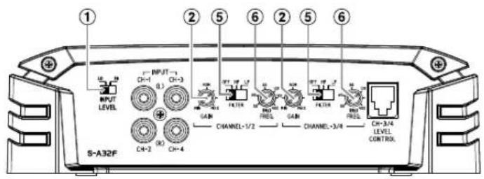
- Before switching each Selector Switch, turn off the power and insert a small screwdriver, etc., perpendicularly to the Switch.
S-A60M
S-A32F
S-A55V

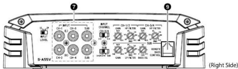
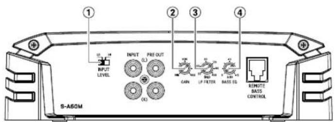
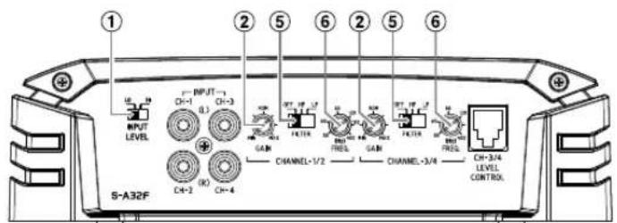
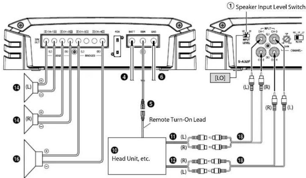
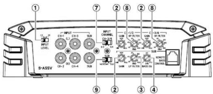
① Speaker Input Level Switch
Switch according to the Speaker input mode.
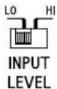
a) When making a speaker input connection with RCA Extension Cables (sold separately), set to "LO".
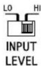
b) When making a speaker input connection with Speaker-RCA Conversion Cables (sold separately), set to "HI".
② Input Gain Adjustment Control
Set the S-A60M/S-A32F/S-A55V input gain to the minimum position. Using a dynamic CD as a source, increase the head unit volume until the output distorts. Then, reduce the volume 1 step (or until the output is no longer distorted). Now, increase the amplifier gain until the sound from the speakers becomes distorted. Reduce the gain slightly so the sound is no longer distorted to achieve the optimum gain setting.
③ Crossover Frequency Adjustment Knob (LP FILTER) (S-A60M/S-A55V only)
Use this control to adjust the crossover frequency between 50 Hz to 400 Hz.
④ Bass EQ Adjustment Knob (S-A60M/S-A55V only)
Add a 50 Hz bass boost up to +12 dB to tune your bass response.
⑤ Crossover Mode Selector Switch (S-A32F only)

a) Set to the "OFF" position when the amplifier will be used for driving full range speakers or when using an external electronic crossover. The full frequency bandwidth will be output to the speakers with no high or low frequency attenuation.

b) Set to the "HP" position when the amplifier is used to drive a tweeter/midrange system. The frequencies below the crossover point will be attenuated at 12 dB/octave.
NOTE:
- In this case the maximum Bass EQ boost level is reduced.

c) Set to the "LP" position when the amplifier is used to drive a subwoofer. The frequencies above the crossover point will be attenuated at 12 dB/octave.
⑥ Crossover Frequency Adjustment Knob (S-A32F only)
Use this control to adjust the crossover frequency between 50 Hz to 400 Hz.
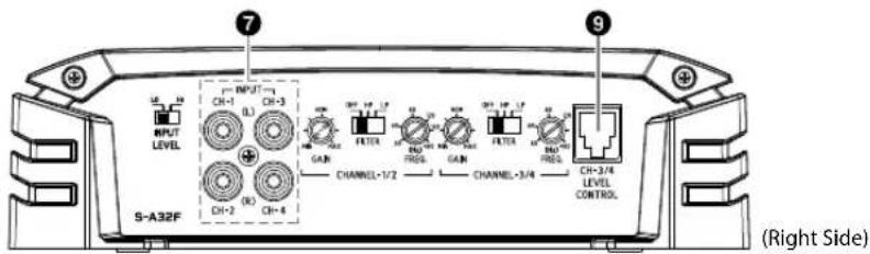
⑦ Input Channel Selector Switch (CH-3/4) (S-A55V only)
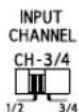
a) This switch setting is for selecting either 2-channel or 4-channel input mode. When set to "1/2", signal will be copied from CH-1/2 and sent to CH-3/4, eliminating the need for Y-adapters.
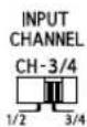
b) Setting this switch to "3/4" will keep both inputs, CH-1/2 and CH-3/4 independent. A 4-channel source is required for this mode.
⑧ Crossover Frequency Adjustment Knob (HP FILTER) (S-A55V only)
Use this control to adjust the crossover frequency between 50 Hz to 400 Hz.
⑨ Input Channel Selector Switch (SUB) (S-A55V only)

a) When this switch is placed in the "1+2+3+4" position, all the signals are mixed and come out from the subwoofer. This setting provides signal to the subwoofer channel when only 4 channel input is available.

b) Setting this switch to "SUB" will send the signal at the inputs of SUB to subwoofer of the S-A55V.
About Power Indicator
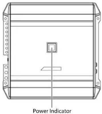
Lights up when power is on. Is off when power is off.
| Indication color Status Solution | ||
| Blue Amplifier circuit is normal. | ||
| Red (blinking) | Operating temperature is high. | Turn down the volume of the head unit (input signal).Decrease the vehicle's interior temperature to a normal level.The indicator color changes to blue. |
| Red Amplifier circuit is abnormal.An electrical short has occurred, or supply current is too high. | Turn off the power supply and eliminate the cause.Then turn on the unit and verify that the indicator color has changed to blue.If it remains red, turn off the unit and consult your dealer. | |

SYSTEM DIAGRAMS
Before making a connection, check the total number of impedance of the speaker connected to the unit. If you have any questions, contact the nearest Alpine dealer.
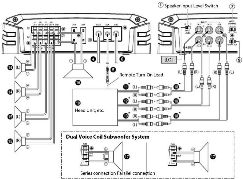
Basic Connection Diagram for S-A60M
① Speaker Output Terminals
② Fuse
③ Power Supply Terminal
4 Battery Lead (sold separately)
5 Remote Turn-On Lead (sold separately)
6 Ground Lead (sold separately)
⑦ RCA Input Jacks
8 Pre-Out Jacks
9 Remote Bass Control (optional)
10 Head Unit, etc.
11 Front Output
12 Rear Output
13 Subwoofer Output
14 Front Speakers
15 Rear Speaker
16 Subwoofer
17 Dual Voice Coil Subwoofer
18 RCA Extension Cable (sold separately)
19 Speaker-RCA Conversion Cable (sold separately)
20 Y-Adapter (sold separately)
SubwooferSystem
![① Speaker Input Level Switch 30A 30A BATT REM GND SPC OUT 4 6 S-ASOM [LO] INPUT LEVEL INPUT FRE OUT (L) (R) 16 Remote Turn-On Lead 5 10 Head Unit, etc. 13* (L) (R) 18*](/content/2026/03/485344/images/b92df181c32b0cca968c64ab16e0a0692aff020f5f1d553e8677ac69194e95a5.jpg)
Dual Voice Coil Subwoofer System
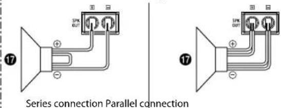
* If the connected head unit does not have a Speaker Output and RCA Extension Cable (18) cannot be used, you can use the Speaker-RCA Conversion Cable (19) (sold separately). For details on how to make a connection, see "About Connecting to the Speaker Input Level System" (page 18).
Multiple Mono Amplifier System
![① Speaker Input Level Switch ① Speaker Input Level Switch ① Speaker Input Level Switch ① Speaker Input Level Switch ① Speaker Input Level Switch ① Speaker Input Level Switch ① Speaker Input Level Switch ① Speaker Input Level Switch ① Speaker Input Level Switch ① Speaker Input Level Switch ① Speaker Input Level Switch ① Speaker Input Level Switch ① Speaker Input Level Switch ① Speaker Input Level Switch ① Speaker Input Level Switch ② S-ASDM S-ASDM [LO] (1) (2) (3) (4) (5) (6) (7) (8) (9) (10) (11) (12) (13) (14) (15) (16) (17) (18) (19) (20) (21) (22) (23) (24) (25) (26) (27) (28) (29) (30) (31) (32) (33) (34) (35) (36) (37) (38) (39) (40) (41) (42) (43) (44) (45) (46) (47) (48) (49) (50) (51) (52) (53) (54) (55) (56) (57) (58) (59) (60) (61) (62) (63) (64) (65) (66) (67) (68) (69) (70) (71) (72) (73) (74) (75) (76) (77) (78) (79) (80) (81) (82) (83) (84) (85) (86) (87) (88) (89) (90) (91) (92) (93) (94) (95) (96) (97) (98) (99) [LO] [LO] [LO] [LO] [LO] [LO] [LO] [LO] [LO] [LO] [LO] [LO] [LO] [LO] [LO] [LO] [LO] [LO] [LO] [LO] [LO] [LO] [LO] [LO] [LO] [LO] [LO] [LO] [LO] [LO] [LO] [LO] [LO] [LO]](/content/2026/03/485344/images/adb52a47a31229601f8d6116a355a50cfb3dcda6cd5e18e12b2f24baad707310.jpg)
Basic Connection Diagram for S-A32F
① Speaker Output Terminals
② Fuse
③ Power Supply Terminal
④ Battery Lead (sold separately)
5 Remote Turn-On Lead (sold separately)
6 Ground Lead (sold separately)
⑦ RCA Input Jacks
8 Pre-Out Jacks
9 Remote Bass Control (optional)
10 Head Unit, etc.
11 Front Output
12 Rear Output
13 Subwoofer Output
14 Front Speakers
15 Rear Speaker
16 Subwoofer
17 Dual Voice Coil Subwoofer
18 RCA Extension Cable (sold separately)
19 Speaker-RCA Conversion Cable (sold separately)
20 Y-Adapter (sold separately)
4 Speaker System
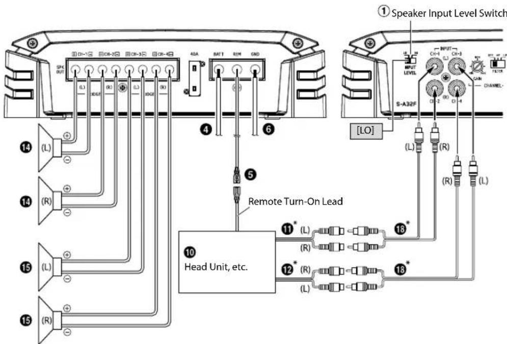
* If the connected head unit does not have a Speaker Output and RCA Extension Cable (18) cannot be used, you can use the Speaker-RCA Conversion Cable (19) (sold separately). For details on how to make a connection, see "About Connecting to the Speaker Input Level System" (page 18).
2 Speaker + Subwoofer System (Bridged Connections)
2 Speaker System (Bridged Connections)
![① Speaker Input Level Switch ④ BATT REM GND ⑤ Remote Turn-On Lead ⑥ ⑮ (L) (R) ⑯ (L) (R) ⑰ (L) (R) ⑱ (L) (R) ⑲ (L) (R) ⑳ (L) (R) ⑪ (L) (R) ⑫ (L) (R) ⑬ (L) (R) ⑭ (L) (R) ⑮ (L) (R) ⑯ (L) (R) ⑰ (L) (R) ⑱ (L) (R) ⑲ (L) (R) ⑳ (L) (R) ⑴ (L) (R) ⑵ (L) (R) ⑶ (L) (R) ⑷ (L) (R) ⑸ (L) (R) ⑹ (L) (R) ⑺ [LO] ⑳ OUTPUT OUTPUT LEVEL S-A32F CHANNEL- Head Unit, etc.](/content/2026/03/485344/images/63f4f742e8927537c3c69c61e3742c37dd8f554f366a8c6f6308c9f543f324c0.jpg)
Basic Connection Diagram for S-A55V
① Speaker Output Terminals
② Fuse
③ Power Supply Terminal
④ Battery Lead (sold separately)
5 Remote Turn-On Lead (sold separately)
6 Ground Lead (sold separately)
⑦ RCA Input Jacks
8 Pre-Out Jacks
9 Remote Bass Control (optional)
10 Head Unit, etc.
11 Front Output
12 Rear Output
13 Subwoofer Output
14 Front Speakers
15 Rear Speaker
16 Subwoofer
17 Dual Voice Coil Subwoofer
18 RCA Extension Cable (sold separately)
19 Speaker-RCA Conversion Cable (sold separately)
20 Y-Adapter (sold separately)
For S-A55V, change the Input Channel Selector Switch (7/1) setting according to the number of channels of the speaker input.
| 5-Channel Input: 14 Channel Input: 2-Channel Input: | 11 | ||
| 7Input Channel Selector Switch (CH-3/4) | 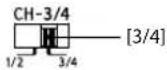 | 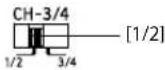 | |
| 9Input Channel Selector Switch (SUB) | 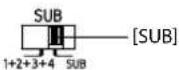 | 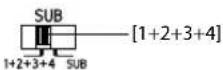 | |
4 Speaker + Subwoofer System
* If the connected head unit does not have a Speaker Output and RCA Extension Cable (18) cannot be used, you can use the Speaker-RCA Conversion Cable (19) (sold separately). For details on how to make a connection, see "About Connecting to the Speaker Input Level System" (page 18).
2 Speaker + Subwoofer System (Bridged Connections)
![① Speaker Input Level Switch ⑦ L1 10 L1 10 CH+1 CH-2 CH-3 CH-4 SUB 30A 30A BATT REM GND ④ ⑥ ⑤ Remote Turn-On Lead ⑭ L5 CH-3 CH-4 OUTPUT LEVEL INPUT R OUTPUT CHANNEL CH=3/4 [LO] ⑪ (L) ⑫ (R) ⑬ (L) ⑭ (R) ⑮ (L) ⑯ (R) ⑰ (L) ⑱ (R) ⑲ (L) ⑳ (R) ⑴ (L) ⑵ (R) ⑶ (L) ⑷ (R) ⑧ (L) ⑨ (R) ⑩ (L) Head Unit, etc.](/content/2026/03/485344/images/0c4697ce42db4cdfb5fadb8120e1d14465f49d0a3bc8fc5260aadcb16dc7a061.jpg)
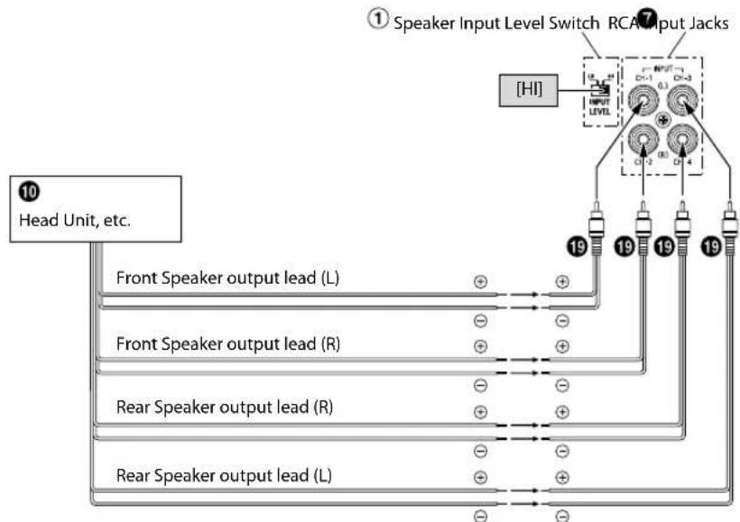
■About Connecting to the Speaker Input Level System
When connecting by using the Speaker-RCA Conversion Cable (19) (sold separately), switch the Speaker Input Level Switch (①) to "HI".
e.g. S-A32F
flowchart
graph TD
    A["① Speaker Input Level Switch RCA Input Jacks"] --> B["HI"]
    B --> C["19"]
    B --> D["19"]
    B --> E["19"]
    B --> F["19"]
    B --> G["19"]
    B --> H["19"]
    B --> I["19"]
    B --> J["19"]
    B --> K["19"]
    B --> L["19"]
    B --> M["19"]
    B --> N["19"]
    B --> O["19"]
    B --> P["19"]
    B --> Q["19"]
    B --> R["19"]
    B --> S["19"]
    B --> T["19"]
    B --> U["19"]
    B --> V["19"]
    B --> W["19"]
    B --> X["19"]
    B --> Y["19"]
    B --> Z["19"]
    B --> AA["19"]
    B --> AB["19"]
    B --> AC["19"]
    B --> AD["19"]
    B --> AE["19"]
    B --> AF["19"]
    B --> AG["19"]
    B --> AH["19"]
    B --> AI["19"]
    B --> AJ["19"]
    B --> AK["19"]
    B --> AL["19"]
    B --> AM["19"]
    B --> AN["19"]
    B --> AO["19"]
    B --> AP["19"]
    B --> AQ["19"]
    B --> AR["19"]
    B --> AS["19"]
    B --> AT["19"]
    B --> AU["19"]
    B --> AV["19"]
    B --> AW["19"]
    B --> AX["19"]
    B --> AY["19"]
    B --> AZ["19"]
    B --> BA["19"]
    B --> BB["19"]
    B --> BC["19"]
    B --> BD["19"]
    B --> BE["19"]
    B --> BF["19"]
    B --> BG["19"]
    B --> BH["19"]
    B --> BI["19"]
    B --> BJ["19"]
    B --> BK["19"]
    B --> BL["19"]
    B --> BM["19"]
    B --> BN["19"]
    B --> BO["19"]
    B --> BP["19"]
    B --> BQ["19"]
    B --> BR["19"]
    B --> BS["19"]
    B --> BT["19"]
    B --> BU["19"]
    B --> BV["19"]
    B --> BW["19"]
    B --> BX["19"]
    B --> BY["19"]
    B --> BZ["19"]
    B --> CA["19"]
    B --> CB["19"]
    B --> CC["19"]
    B --> CD["19"]
    B --> CE["19"]
    B --> CF["19"]
    B --> CG["19"]
    B --> CH["19"]
    B --> CI["19"]
    B --> CJ["19"]
    B --> CK["19"]
- Do not mistake the Speaker Output Lead on the head unit side connected to this unit. Front Speaker output (L)/(R) to CH1/CH2, Rear Speaker output (L)/(R) to CH3/CH4
- For the "Speaker Input Level System" setting, connecting the Remote Turn-On Lead is not required due to the "REMOTE SENSING" function of this product. However, the "REMOTE SENSING" function may not work depending on the signal source connected. In such a case, connect the Remote Turn-On Lead to an incoming power supply cord (accessory power) in the ACC position.
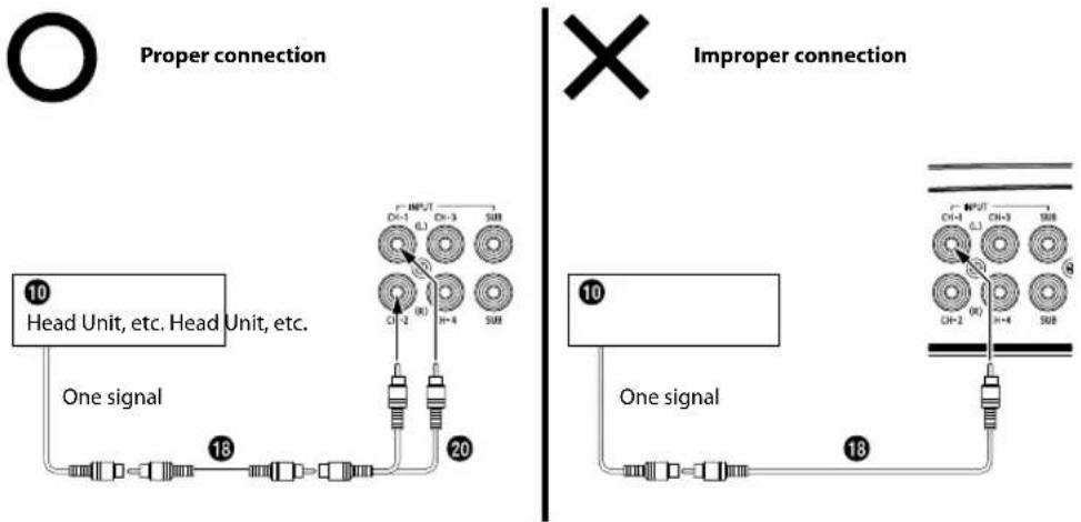
■ Important Tips on Bridging an Amplifier
Low output will result if only one channel input is used. The Y-adapter is not required if a stereo/mono pair line output is used to drive both inputs of the bridged amp.
flowchart
graph TD
    subgraph "Proper connection"
        A["10 Head Unit, etc. Head Unit, etc."] --> B["One signal"]
        B --> C["18"]
        C --> D["20"]
        D --> E["Output"]
    end

    subgraph "Improper connection"
        F["10 One signal"] --> G["18"]
        G --> H["20"]
        H --> I["Output"]
    end

    A --> J["18"]
    J --> K["20"]
    K --> L["Output"]
    style A fill:#f9f,stroke:#333
    style F fill:#f9f,stroke:#333
■Cautions on Power Supply Wires
Use the specified wire size according to the total fuse capacity of the amplifier to be installed and the wire length.
For details on the wire size to be used, refer to the supplied "Cautions on Power Supply Wires Connection" and the following connection example.
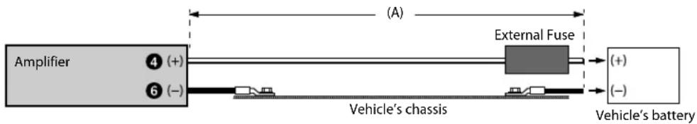
Connection example when installing an amplifier alone
- When the wire length from the amplifier to the vehicle's battery is 5 m Wire size used for (A):
S-A60M/S-A55V: 4 AWG/21 mm²
S-A32F: 8 AWG/8 mm²
- External Fuse capacity: Make it equal to or larger than the fuse capacity of the amplifier
S-A60M/S-A55V: equal to or larger than 60 A
S-A32F: equal to or larger than 40 A
flowchart
graph LR
    A["Amplifier"] --> B["④ (+)"]
    A --> C["⑥ (-)"]
    B --> D["Vehicle's chassis"]
    C --> D
    D --> E["External Fuse"]
    E --> F["Vehicle's battery"]
    style A fill:#f9f,stroke:#333
    style B fill:#ccf,stroke:#333
    style C fill:#ccf,stroke:#333
    style D fill:#cfc,stroke:#333
    style E fill:#fcc,stroke:#333
    style F fill:#fcc,stroke:#333
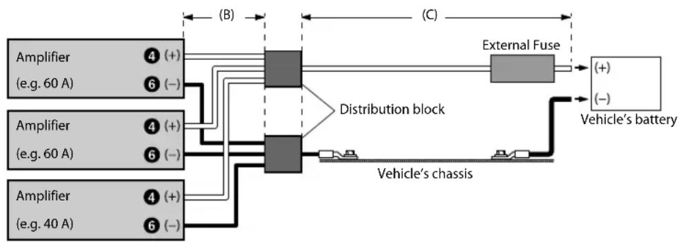
Connection example when installing two amplifiers with a fuse capacity of 60 A and one amplifier with 40 A
- When the wire length from each amplifier to the distribution block is 1 m Wire size used for (B): 8 AWG/8 mm ^2
- When the wire length from the distribution block to the vehicle's battery is 4 m Wire size used for (C): 1/0 AWG/53 mm² (or 4 AWG × 2/21 mm² × 2)
- External Fuse capacity: Make it equal to or larger than total fuse capacity of the number of amplifiers installed
60 A + 60 A + 40 A = equal to or larger than 160 A
flowchart
graph LR
    A["Amplifier (e.g. 60 A)"] --> B["④ (+)"]
    A --> C["⑥ (-)"]
    D["Amplifier (e.g. 60 A)"] --> E["④ (+)"]
    D --> F["⑥ (-)"]
    G["Amplifier (e.g. 40 A)"] --> H["④ (+)"]
    G --> I["⑥ (-)"]
    B --> J["Distribution block"]
    C --> J
    E --> J
    F --> J
    H --> J
    I --> J
    J --> K["External Fuse"]
    K --> L["Vehicle's battery"]
    J --> M["Vehicle's chassis"]
    style J fill:#99ccff,stroke:#333
NOTE:
- If the length of the power and ground cables exceed 1m , or if you connect more than one amplifier, a distribution block should be used.
SPECIFICATIONS
S-A60M
| Performance | ||
| Power Output | Per Channel, Ref.: 4 Ω, 14.4 V 330 W RMS × 1 | |
| Per Channel, Ref.: 2 Ω, 14.4 V 600 W RMS × 1 | ||
| THD+N | Ref.: 10 W into 4 Ω ≤0.03% | |
| Ref.: 10 W into 2 Ω ≤0.05% | ||
| Ref.: Rated Power into 4 Ω ≤0.2% | ||
| Ref.: Rated Power into 2 Ω ≤1.0% | ||
| S/N Ratio | IHF A-wtd + AES-17Ref.: 1 W into 4 Ω | >85 dB |
| IHF A-wtd + AES-17Ref.: Rated Power into 4 Ω | >105 dB | |
| Frequency Response | +0/-3 dB, Ref.: 1 W into 4 Ω 10 Hz - 400 Hz | |
| +0/-1 dB, Ref.: 1 W into 4 Ω 20 Hz - 300 Hz | ||
| Damping Factor Ref.: 10 W | into 4 Ω at 100 Hz >1,000 | |
| Control | ||
| Input Sensitivity | RCA InputRef.: Rated Power into 4 Ω | Hi: 0.5 - 10 VL0: 0.2 - 4.0 V |
| Crossover | Variable HPF/LPF | LPF: 50 Hz - 400 Hz(-24 dB/oct.) |
| Equalizer Bass EQ (fc=50 Hz) | 0 to +12 dB(Variable) | |
| Remote Level* Linear Attenuation 0 to -20 dB | ||
| General | ||
| Input Impedance >10 kΩ | ||
| Preamp Output CH-1/2 Input Pass-through, Buffered | 4 V max | |
| Dimensions | Width | 204 mm (8-1/8") |
| Height | 57.5 mm (2-3/8") | |
| Depth | 204 mm (8-1/8") | |
| Weight | 2.2 kg (4 lb 13 oz) | |
* Requires optional RUX-KNOB.2.
NOTE:
- Specifications and design are subject to change without notice.
S-A32F
| Performance | ||
| Power Output | Per Channel, Ref.: 4 Ω, 14.4 V 55 W RMS × 4 | |
| Per Channel, Ref.: 2 Ω, 14.4 V 80 W RMS × 4 | ||
| Bridged, Ref.: 4 Ω, 14.4 V 160 W RMS × 2 | ||
| THD+N | Ref.: 10 W into 4 Ω ≤0.03% | |
| Ref.: 10 W into 2 Ω ≤0.05% | ||
| Ref.: Rated Power into 4 Ω | ≤0.08%Power at 50 W | |
| Ref.: Rated Power into 2 Ω | ≤0.1%Power at 75 W | |
| S/N Ratio | IHF A-wtd + AES-17Ref.: 1 W into 4 Ω | >83 dB |
| IHF A-wtd + AES-17Ref.: Rated Power into 4 Ω | >98 dBPower at 50 W | |
| Frequency Response | +0/-3 dB, Ref.: 1 W into 4 Ω 10 Hz - 30 kHz | |
| +0/-1 dB, Ref.: 1 W into 4 Ω 20 Hz - 20 kHz | ||
| Damping Factor Ref.: 10 W | into 4 Ω at 100 Hz >100 | |
| Control | ||
| Input Sensitivity | RCA InputRef.: Rated Power into 4 Ω | Hi: 0.5 - 10 VL0: 0.2 - 4.0 VPower at 50 W |
| Crossover | Variable HPF/LPF | 50 Hz - 400 Hz(-12 dB/oct.) |
| Remote Level* Linear Attenuation | CH-3/4:0 to -20 dB | |
| General | ||
| Input Impedance >10 kΩ | ||
| Dimensions | Width 204 mm (8-1/8") | |
| Height 57.5 mm (2-3/8") | ||
| Depth 204 mm (8-1/8") | ||
| Weight 1.9 kg (4 lb 3 oz) | ||
* Requires optional RUX-KNOB.2.
NOTE:
- Specifications and design are subject to change without notice.
S-A55V
| CH-1/2/3/4 SUBWOOFER | |||
| Performance | |||
| Power Output | Per Channel, Ref.: 4 Ω, 14.4 V 40 W RMS × 4 200 W RMS × 1 | ||
| Per Channel, Ref.: 2 Ω, 14.4 V 60 W RMS × 4 300 W RMS × 1 | |||
| Bridged, Ref.: 4 Ω, 14.4 V 120 W RMS × 2 - | |||
| THD+N | Ref.: 10 W into 4 Ω ≤0.03% ≤0.03% | ||
| Ref.: 10 W into 2 Ω ≤0.05% ≤0.05% | |||
| Ref.: Rated Power into 4 Ω ≤0.07% ≤0.07% | |||
| Ref.: Rated Power into 2 Ω ≤0.1% ≤0 1% | |||
| S/N Ratio | IHF A-wtd + AES-17Ref.: 1 W into 4 Ω | >83 dB >83 dB | |
| IHF A-wtd + AES-17Ref.: Rated Power into 4 Ω | >98 dB >98 dB | ||
| Frequency Response | +0/-3 dB, Ref.: 1 W into 4 Ω 50 Hz - 30 kHz 10 Hz - 400 Hz | ||
| +0/-1 dB, Ref.: 1 W into 4 Ω 60 Hz - 20 kHz 20 Hz - 300 Hz | |||
| Damping Factor Ref.: 10 W into 4 Ω at 100 Hz >100 >750 | |||
| Control | |||
| Input Select | Selectable Input SignalConfiguration (2ch/4ch Input) | CH-3/4:CH-1/2 or CH-3/4 | CH-1+2+3+4or SUB |
| Input Sensitivity | RCA InputRef.: Rated Power into 4 Ω | Hi: 0.5 - 10 VLo: 0.2 - 4.0 V | Hi: 0.5 - 10 VLo: 0.2 - 4.0 V |
| Crossover | Variable HPF/LPF | HPF: 50 Hz - 400 Hz(-12 dB/oct.) | LPF: 50 Hz - 400 Hz(-24 dB/oct.) |
| Remote Level* | Linear Attenuation | -0 to -20 dB | |
| General | |||
| Input Impedance | >10 kΩ | ||
| Dimensions | Width | 286 mm (11-3/8") | |
| Height | 57.5 mm (2-3/8") | ||
| Depth | 204 mm (8-1/8") | ||
| Weight | 2.9 kg (6 lb 6 oz) | ||
* Requires optional RUX-KNOB.2.
NOTE:
- Specifications and design are subject to change without notice.
Français
TABLE DES MATIÈRES
AVERTISSEMENT....1
SERVICE APRÈS-VENTE 2
ACCESSOIRES....3
INSTALLATION....3
CONNEXIONS 4
LISTE DE VÉRIFICATION DES CONNEXIONS ......8
RÉGLAGES DE COMMUTATEUR 9
DIAGRAMMES DU SYSTÈME 12
SPÉCIFICATIONS....20
AVERTISSEMENT
(P. ex., S-A32F)
CONNEXIONS
S-A32F
S-A32F
S-A55V
natural_image
Technical line drawing of a rectangular electronic device with mounting flanges and a central square component (no text or symbols)


- ALPINE®
- S-A60M
- MONO POWER AMPLIFIER
- S-A32F
- CHANNEL POWER AMPLIFIER
- S-A55V
- CHANNEL + MONO POWER AMPLIFIER
- ALPINE ELECTRONICS GmbH
- ALPINE ELECTRONICS FRANCE S.A.R.L.
- English
- CONTENTS
- WARNING
- Points to Observe for Safe Usage
- DO NOT OPERATE ANY FUNCTION THAT TAKES YOUR ATTENTION AWAY FROM SAFELY DRIVING YOUR VEHICLE.
- KEEP THE VOLUME AT A LEVEL WHERE YOU CAN STILL HEAR OUTSIDE NOISES WHILE DRIVING.
- DO NOT DISASSEMBLE OR ALTER.
- USE THIS PRODUCT FOR MOBILE 12V APPLICATIONS.
- USE THE CORRECT AMPERE RATING WHEN REPLACING FUSES.
- DO NOT BLOCK VENTS OR RADIATOR PANELS.
- MAKE THE CORRECT CONNECTIONS.
- USE ONLY IN CARS WITH A 12 VOLT NEGATIVE GROUND.
- BEFORE WIRING, DISCONNECT THE CABLE FROM THE NEGATIVE BATTERY TERMINAL.
- DO NOT ALLOW CABLES TO BECOME ENTANGLED IN SURROUNDING OBJECTS.
- DO NOT SPLICE INTO ELECTRICAL CABLES.
- DO NOT DAMAGE PIPE OR WIRING WHEN DRILLING HOLES.
- DO NOT USE BOLTS OR NUTS IN THE BRAKE OR STEERING SYSTEMS TO MAKE GROUND CONNECTIONS.
- KEEP SMALL OBJECTS SUCH AS BATTERIES OUT OF THE REACH OF CHILDREN.
- CAUTION
- HALT USE IMMEDIATELY IF A PROBLEM APPEARS.
- HAVE THE WIRING AND INSTALLATION DONE BY EXPERTS.
- USE SPECIFIED ACCESSORY PARTS AND INSTALL THEM SECURELY.
- ARRANGE THE WIRING SO IT IS NOT CRIMPED OR PINCHED BY A SHARP METAL EDGE.
- DO NOT INSTALL IN LOCATIONS WITH HIGH MOISTURE OR DUST.
- SERVICE CARE
- ♦ IMPORTANT NOTICE
- IMPORTANT
- ◆ For European Customers
- ◆ For Customers in other Countries
- IMPORTANT NOTICE
- ACO
- INS
- ACCESSORIES
- INSTALLATION
- CONNECTIONS
- To prevent external noise from entering the audio system
- ① Speaker Output Terminals
- About Subwoofer Input/Output (S-A60M/S-A55V only)
- About Bridged Connections (S-A32F/S-A55V only)
- NOTE:
- ② Fuse
- ③ Power Supply Terminal
- ④ Battery Lead (sold separately)
- ⑤ Remote Turn-On Lead (sold separately)
- ⑥ Ground Lead (sold separately)
- ⑦ RCA Input Jacks
- Pre-Out Jacks (S-A60M only)
- ⑨ Remote Bass Control (optional)
- Cautio
- NOTES:
- Cautions on wire lead connections
- Power Supply Terminal
- Speaker Output Terminals
- CONNECTION CHECK LIST
- Please check your head unit for the conditions listed below:
- Remote Turn-On Lead
- SWITCH SETTINGS
- ① Speaker Input Level Switch
- ② Input Gain Adjustment Control
- About Power Indicator
- SYSTEM DIAGRAMS
- Basic Connection Diagram for S-A60M
- Basic Connection Diagram for S-A32F
- Basic Connection Diagram for S-A55V
- ■About Connecting to the Speaker Input Level System
- e.g. S-A32F
- ■ Important Tips on Bridging an Amplifier
- ■Cautions on Power Supply Wires
- Connection example when installing an amplifier alone
- Connection example when installing two amplifiers with a fuse capacity of 60 A and one amplifier with 40 A
- SPECIFICATIONS
- Français
- TABLE DES MATIÈRES
- AVERTISSEMENT
- CONNEXIONS
Brand : ALPINE
Model : SA60M
Category : Receiver