
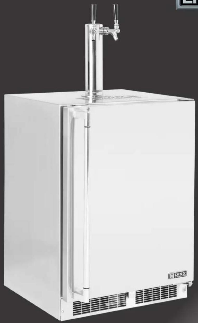
LM24BFL - Fridge LYNX - Free user manual and instructions
Find the device manual for free LM24BFL LYNX in PDF.
| Product Type | Outdoor Refrigerator / Draft Beer Dispenser |
| Brand | Lynx |
| Model | LM24BFL |
| Height (adjustable) | 33.75 to 34.75 in (85.7 to 88.3 cm) |
| Power Supply | 115 V, 15 A, dedicated grounded circuit |
| Temperature Range | 34 °F to 46 °F (1 °C to 8 °C) |
| Keg Capacity | 1/2 barrel (15.5 gal), 1/4 barrel (7.75 gal), or 2 × 1/6 barrel (5.1 gal each) |
| CO2 Cylinder | 5 lbs, included (empty) |
| CO2 Regulator | Single or dual gauge depending on configuration |
| Main Functions | Draft beer dispensing, refrigeration, electronic temperature control, alarms (door open, temperature, sensor) |
| Maintenance and Cleaning | Regular cleaning of the dispensing system, front grille, interior, and stainless steel; winterization recommended |
| Safety | Grounding required, do not use extension cord, child entrapment warnings, CO2 handling |
| Spare Parts and Repairability | Faucet cleaning kit (ref. 42242373), coupler, regulator, tower; Lynx customer service (888-289-5969) |
| General Information | Under-counter installation possible, adjustable leveling legs, removable front grille, insulation for outdoor use |
Frequently Asked Questions - LM24BFL LYNX
User questions about LM24BFL LYNX
0 question about this device. Answer the ones you know or ask your own.
Ask a new question about this device
Download the instructions for your Fridge in PDF format for free! Find your manual LM24BFL - LYNX and take your electronic device back in hand. On this page are published all the documents necessary for the use of your device. LM24BFL by LYNX.
USER MANUAL LM24BFL LYNX
Unpacking your appliance 3
Warranty registration 3
Installing your appliance 4
Cabinet clearances 4
Leveling the appliance 4
Electrical connection 5
Product dimensions 6
Using your Electronic control 8
Starting your appliance 8
Turning your appliance "ON" or "OFF" 8
Adjusting the temperature 8
Beverage dispenser operation 8
Alarms 8
Door ajar 8
Temperature sensor fault 8
High and Low temperature alarms 8
Alarm mute 9
Using your beverage dispenser. 10
Shelving 10
Tap equipment and assembly. 11
CO2 regulator 15
Drain kit 16
Care and cleaning 16
Cleaning the drain sump 16
Keg coupler cleaning 17
Faucet cleaning 17
Tap cleaning kit 18
Cleaning the beer line 18
Front grille 18
Cabinet 18
Interior 18
Long term storage / winterization 19
Stainless steel maintenance 21
Energy saving tips 21
Obtaining service 22
The Lynx Story 22
Troubleshooting 23
Important Safety Instructions
Warnings and safety instructions appearing in this guide are not meant to cover all possible conditions and situations that may occur. Common sense, caution, and care must be exercised when installing, maintaining, or operating this appliance.
Recognize Safety Symbols, Words, and Labels.

WARNING
WARNING - You can be killed or seriously injured if you do not follow these instructions.

CAUTION
CAUTION-Hazards or unsafe practices which could result in personal injury or property / product damage.
NOTE
NOTE-Important information to help assure a problem free installation and operation.

WARNING
State of California Proposition 65 Warning:
This product contains one or more chemicals known to the State of California to cause cancer.

WARNING
State of California Proposition 65 Warning:
This product contains one or more chemicals known to the State of California to cause birth defects or other reproductive harm..
UNPACKING YOUR APPLIANCE

WARNING
EXCESSIVE WEIGHT HAZARD
Use two or more people to move product. Failure to do so can result in personal injury.
Remove Interior Packaging
Your appliance has been packed for shipment with all parts that could be damaged by movement securely fastened. Remove internal packing materials and any tape holding internal components in place. The owners manual is shipped inside the product in a plastic bag along with the warranty registration card, and other accessory items.
Important
Keep your carton and packaging until your appliance has been thoroughly inspected and found to be in good condition. If there is damage, the packaging will be needed as proof of damage in transit. Afterwards please dispose of all items responsibly.

WARNING
WARNING - Dispose of the plastic bags which can be a suffocation hazard.
Note to Customer
This merchandise was carefully packed and thoroughly inspected before leaving our plant. Responsibility for its safe delivery was assumed by the retailer upon acceptance of the shipment. Claims for loss or damage sustained in transit must be made to the retailer.
NOTE
DO NOT RETURN DAMAGED MERCHANDISE TO THE MANUFACTURER - FILE THE CLAIM WITH THE RETAILER.

CAUTION
If the appliance was shipped, handled, or stored in other than an upright position for any period of time, allow the appliance to sit upright for a period of at least 24 hours before plugging in. This will assure oil returns to the compressor. Plugging the appliance in immediately may cause damage to internal parts.
Warranty Registration
It is important you send in your warranty registration card immediately after taking delivery of your appliance or you can register online at
www.lynxgrills.com/support/registration
The following information will be required when registering your appliance.
Service/Model Number
Serial Number
Date of Purchase
Dealer's name and address
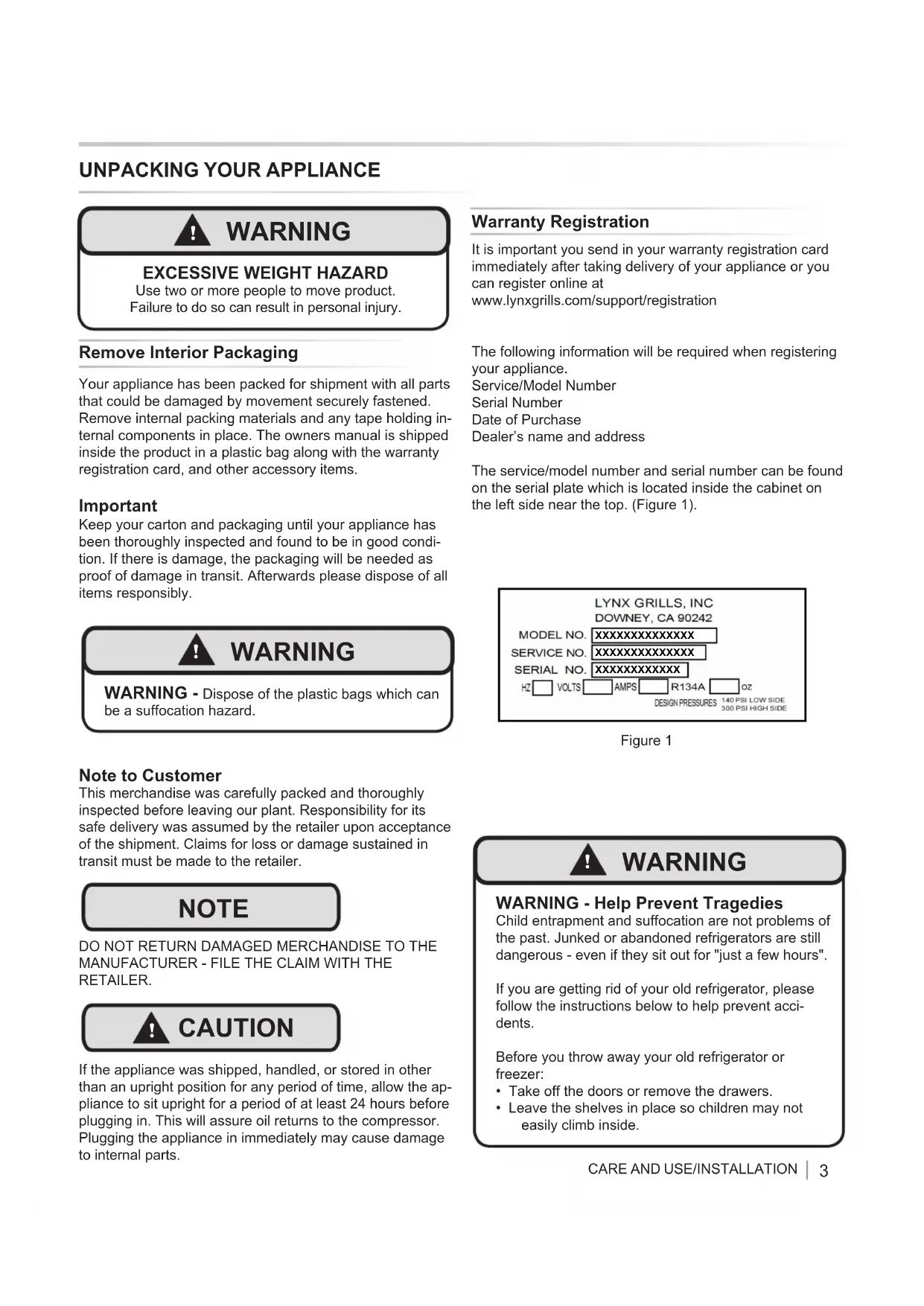
The service/model number and serial number can be found on the serial plate which is located inside the cabinet on the left side near the top. (Figure 1).
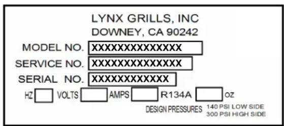
Figure 1

WARNING
WARNING - Help Prevent Tragedies
Child entrapment and suffocation are not problems of the past. Junked or abandoned refrigerators are still dangerous - even if they sit out for "just a few hours".
If you are getting rid of your old refrigerator, please follow the instructions below to help prevent accidents.
Before you throw away your old refrigerator or freezer:
Take off the doors or remove the drawers.
- Leave the shelves in place so children may not easily climb inside.
INSTALLING YOUR APPLIANCE
Select Location
The proper location will ensure peak performance of your appliance. We recommend a location where the unit will be out of direct sunlight and away from heat sources. To ensure your product performs to specifications, the recommended installation location temperature range is from 55 to 115^ (13 to 46^ ).
Cabinet Clearance
Ventilation is required from the bottom front of the appliance. Keep this area open and clear of any obstructions. Adjacent cabinets and counter top can be installed around the appliance as long as the front grille remains unobstructed.
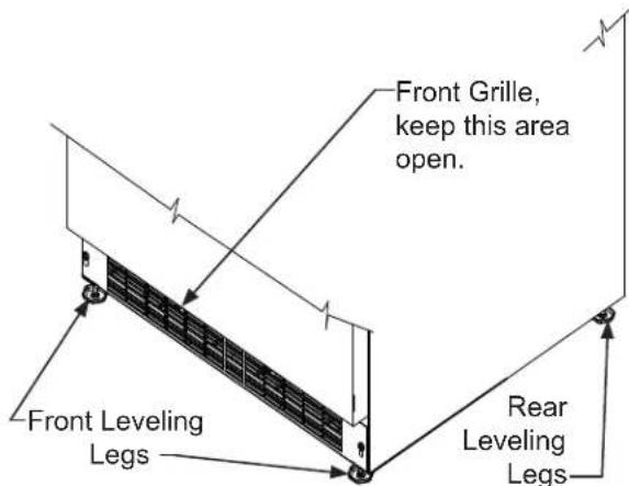
Figure 2
Leveling Legs
Adjustable legs at the front and rear corners of the appliance should be set so the unit is firmly positioned on the floor and level from side to side and front to back. The overall height of your appliance may be adjusted between the minimum, 3334 (85.7 cm), by turning the leveling leg in (CW) and the maximum, 3434 (88.3 cm) by turning the leveling leg out (CCW).
To adjust the leveling legs, place the appliance on a solid surface and protect the floor beneath the legs to avoid scratching the floor. With the assistance of another person, lean the appliance back to access the front leveling legs. Raise or lower the legs to the required dimension by turning the legs. Repeat this process for the rear by tilting the appliance forward using caution. On a level surface check the appliance for levelness and adjust accordingly.
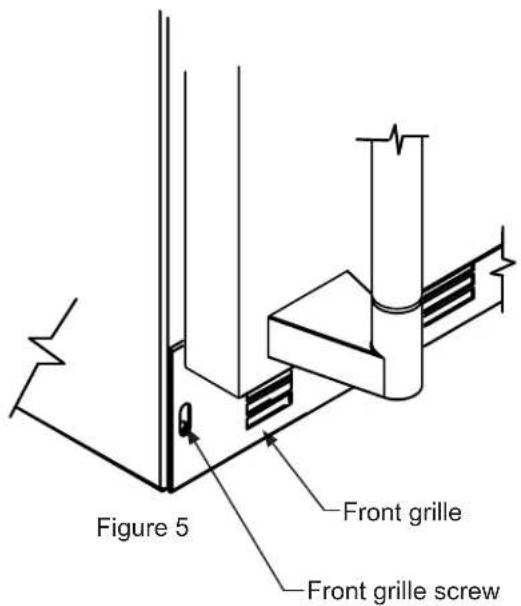
The front grille screws may be loosened and the grille adjusted to the desired height. When adjustment is complete, tighten the two front grille screws. (See Figure 5).

CAUTION
FrontGrille
Do not obstruct the front grille. The openings within the front grille allow air to flow through the condenser heat exchanger. Restrictions to this air flow will result in increased energy usage and loss of cooling capacity. For this reason it is important this area not be obstructed and the grille openings kept clean. Lynx Grills does not recommend the use of a custom made grille as air flow may be restricted. (See Figure 2).
INSTALLING YOUR APPLIANCE
Figure 3
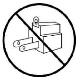
Figure 4

WARNING
Electrical Shock Hazard
- Do not use an extension cord with this appliance. They can be hazardous and can degrade product performance.
- This appliance should not, under any circumstances, be installed to an un-grounded electrical supply.
- Do not remove the grounding prong from the power cord. (See Figure 3).
- Do not use an adapter. (See Figure 4).
- Do not splash or spray water from a hose on the appliance. Doing so may cause an electrical shock, which may result in severe injury or death.
Electrical Connection
A grounded 115 volt, 15 amp dedicated circuit is required.
This product is factory equipped with a power supply cord that has a three-pronged, grounded plug. It must be plugged into a mating grounding type receptacle in accordance with the National Electrical Code and applicable local codes and ordinances (see Figure 6). If the circuit does not have a grounding type receptacle, it is the responsibility and obligation of the customer to provide the proper power supply. The third ground prong should not, under any circumstances, be cut or removed.
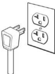
Figure 6
NOTE
Ground Fault Circuit Interrupters (GFCI) are prone to nuisance tripping which will cause the appliance to shut down. GFCI's are generally not used on circuits with power equipment that must run unattended for long periods of time, unless required to meet local building codes and ordinances.
PRODUCT DIMENSIONS
| MODEL | ROUGH-IN OPENING DIMENSIONS CABINET DIMENSIONS | ||||||||
| "A" | "B" | "C" | "D" | "E" | "F" | "G" | "H" | "J" | |
| LM24BF | 24"(61 cm) | **34" to 35"(86.4 to 88.9 cm) | * | 23¼"(60.7 cm) | 33¼" to 34¼"(85.7 to 88.3 cm) | 23½"(60.2 cm) | 26¼"(67.9 cm) | 46½"(117.9 cm) | 26¾"(67.9 cm) |
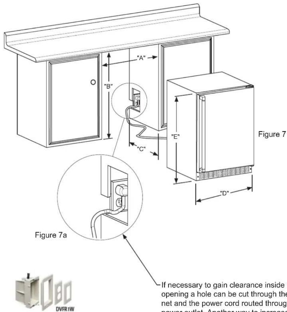
Figure 8
If necessary to gain clearance inside the rough-in opening a hole can be cut through the adjacent cabinet and the power cord routed through this hole to a power outlet. Another way to increase the available opening depth is to recess the power outlet into the rear wall to gain the thickness of the power cord plug. Not all recessed outlet boxes will work for this application as they are too narrow, but a recessed outlet box equivalent to Arlington #DVFR1W is recommended for this application, (see Figure 8).
PRODUCT DIMENSIONS
| MODEL | PRODUCT DATA | |
| ELECTRICAL REQUIREMENTS# | PRODUCT WEIGHT | |
| LM24BF 115V/60Hz/15A | 140 lbs (63.6 kg) | |
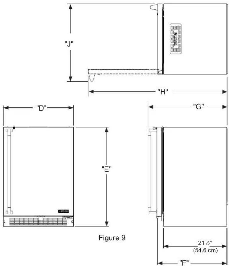
- Depth dimension of rough-in opening may vary depending on each individual installation. To recess entire door "F" dimension plus 1" (2.5 cm) for thickness of power cord plug is required.
** Minimum rough-in opening required is to be larger than the adjusted height of the cabinet.
A grounded 15 amp dedicated circuit is required. Follow all local building codes when installing electrical and appliance.
USING YOUR ELECTRONIC CONTROL
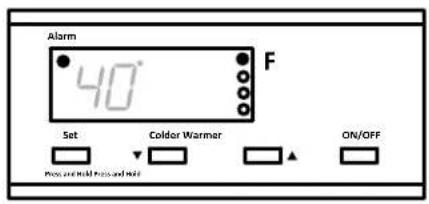
Figure 10 close-up of control
Starting Your Refrigerator
Plug the beer dispenser power cord into a wall outlet. Your beer dispenser will begin cooling after power is applied. If your beer dispenser does not start, check that the beer dispenser is turned on and the set temperature is cold enough.
Turning Your Refrigerator ON or OFF
If the beer dispenser is on, the beer dispenser temperature will be shown on the display. To turn the beer dispenser off, press and hold the "ON/OFF" button for three (3) seconds. "OFF" will appear on the display.
If the beer dispenser is not on, "OFF" will be shown on the display. To turn the beer dispenser on, press and hold the "ON/OFF" button for three (3) seconds. The beer dispenser temperature will be shown on the display.
Set temperature
To set the beer dispenser temperature, press and hold the "SET" button. When the "SET" button is pressed, the display will show the set temperature. While holding the "SET" button, press the "WARMER" or "COLDER" buttons to adjust set temperature.
Beverage Dispenser Operation
The available temperature range of the beer dispenser is 34^ to 46^ (1^ to 8^)
It may take up to 24 hours for your beer dispenser to reach desired temperature. This will depend on amount of content loaded and number of door opening and closings.
For best results allow beer dispenser to "pull down" to desired set temperature before loading. Once contents are loaded, allow at least 48 hours for temperature to stabilize before making any adjustments to the set temperature.
Alarms
Your electronic control will monitor beer dispenser function and alert you with a series of audible and visual alarms.
- Door Ajar Alarm: If the door has been left open for over five (5) minutes, the alarm will sound in one (1) second intervals. The
display panel will flash "do" and the Alarm LED located at the top left of the display below the word "Alarm" will be illuminated. This will stop as soon as the door is closed.

- Temperature Sensor Fault: If the controller detects that the temperature sensor is not properly functioning, a temperature
sensor alarm will sound in one (1) second intervals. "E1" will flash on the display panel and the Alarm LED located at the top left of the display below the word "Alarm" will be illuminated. Please call Lynx Grills Customer Service or your dealer if this error code is displayed.

- High and Low Temperature Alarm: If the storage compartment temperature deviates excessively from the set-point temperature, the alarm will sound in (1) second intervals. The display panel will flash either "Hi" or "Lo" depending upon the condition and the Alarm LED
light at the top left of the display below the word "Alarm" will be illuminated. The alarm will remain active until the condition is corrected.
USING YOUR ELECTRONIC CONTROL
NOTE
After a high temperature alarm condition, check all perishables to ensure they are safe for consumption.
NOTE
The temperature alarm may occur as a result of high usage or introduction of warm contents to the storage compartment. If the temperature alarm continues to occur, your unit may require service.
Alarm Mute
Press any key to mute the audible portion of an alarm.
NOTE
This action will only mute the alarm. If the condition that caused the alarm continues, the alarm code will continue to flash and will sound for 20 seconds every 60 minutes.
USING YOUR BEVERAGE DISPENSER
Shelving
The unit is shipped with the (2) shelves taped in place in the upper and the lower shelf positions. Remove them from the refrigerator and arrange them as follows when setting up your unit.
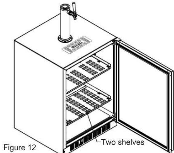
If you are not serving beer on tap, your keg dispenser can be used as a refrigerator by placing both shelves on the mounting brackets as shown in Figure 13. The shelves are marked upper and lower, The upper shelf should be placed in the top shelf position and the shelf marked lower should be placed in the bottom shelf position.

CAUTION
If you are using the appliance as a refrigerator for perishable foods, the set-point temperature should be set between 34^ and 42^ (1.2°C and 5.7°C).

CARE AND USE/INSTALLATION
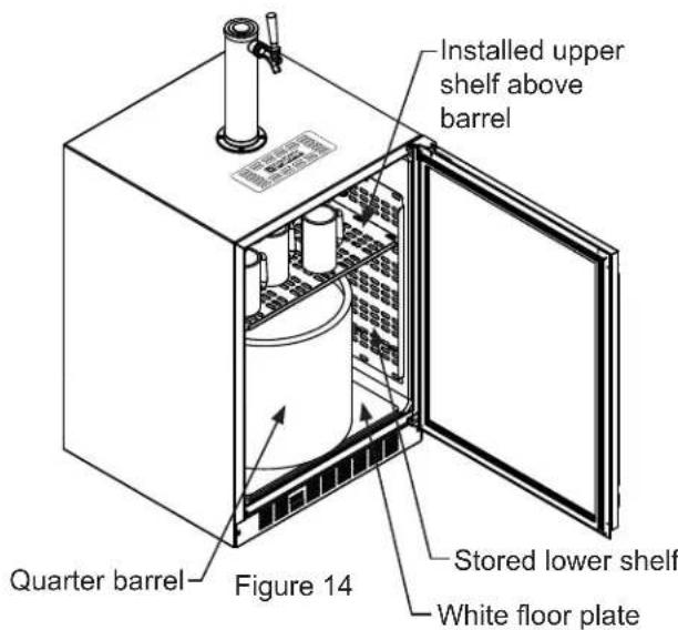
If you are using a quarter barrel of beer, you can add shelf space for keeping your mugs chilled. The quarter barrel must set on the floor, it cannot fit on the shelf, see
Figure 14. Be sure the white floor plate is in the bottom of the interior compartment before positioning the barrel.
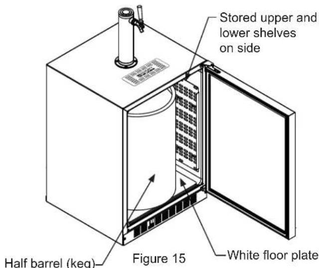
If you are using a half barrel (keg) or (2) 1/6 barrels, place the two shelves on the right side of the keg dispenser on the two mounting hooks for storage. (See Figure 15). Be sure the white floor plate is in the bottom of the interior compartment before positioning the barrel(s).
USING YOUR BEVERAGE DISPENSER
This beer dispensing unit will support one half (1 / 2) barrel or one quarter (1 / 4) barrel. The double draft tower units can support two sixth (1 / 6) barrels of beer. See chart below for quantity of beer in each barrel size.
Table A
| Barrel Sizes | |||
| 1/6 barrel 1/4 Barrel 1/2 Barrel | |||
| Height | 23%16"(59.2 cm) | 14 13%16"(37.6 cm) | 23%16"(59.2 cm) |
| Diameter | 9¼"(23.5 cm) | 17"(43.2 cm) | 17" to 17¼"(43.2 to 43 cm) |
| Gallons 5.1 | 6 7.75 15.5 | ||
| #12 ounce Glasses | 60 82 163 | ||
Table B
| Keg Size | #of kegs per 5 pound CO2Tank |
| 5 gallon Corny 15 | to 22 |
| 1/6 barrel 14 to | 21 |
| 1/4 Barrel 10 to | 14 |
| 1/2 Barrel 5 to | 7 |
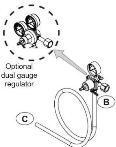
Tap Equipment and Assembly
Your dispensing kit includes the following parts:
Polished stainless steel tower with clear beer line (single or double dispense)
Tower Gasket
Phillips oval head screws
Knob for Tower (Faucet Handle)
Keg coupler(s)
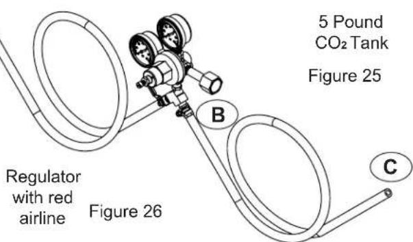
CO_2 regulator with red gas line(s) attached
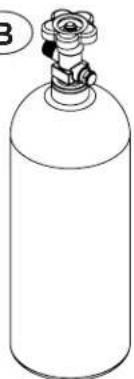
Empty 5 pound CO_2 tank
Plastic clamp(s) large and small
Faucet wrench
Tools required for installation:
Flat bladed screwdriver
Phillips screwdriver
Pliers
Adjustable wrench or a 1 18 open end wrench
1 / 2 open end wrench

WARNING
CO_2 can be dangerous. If it becomes difficult to breathe and/or your head starts to ache, a high concentration of carbon dioxide may be present. Leave the area immediately.
- The CO_2 tank must always be connected to the regulator. Never connect the tank to the keg.
- The CO_2 tank must be securely mounted in the upright position. Secure it with the chain provided.
- Never drop or throw the CO_2 tank.
- Keep the CO_2 tank away from heat.
-
Ventilate the area after a CO_2 leak.
-
Remove shelving and packaged components from the interior of the refrigerator before beginning the assembly process.
- Take your empty 5 pound CO_2 tank to your local gas supply dealer to be filled. You can usually find them in your "yellow pages" under "Welding Supply" or "Fire Protection". One 5 pound tank can process many legs (see Table B).
- Tower mounting (if you are installing the unit under a counter skip to step 4). If you are mounting the tower directly to the top of the refrigerator, first remove the four screws from the top of the refrigerator. Remove the foam plug from the large hole in the top of the refrigerator. Feed the clear beer line through the tower gasket and the large hole in the refrigerator top. Align the 4 holes in the tower with the 4 holes in the refrigerator top and secure the tower with the 4 screws removed previously. Skip to step 5.
USING YOUR BEER DISPENSER
Single Dispense Tower Kit Double Dispense Tower Kit
Connect A to A ,etc....

Figure 17
Hose clamps use for connections


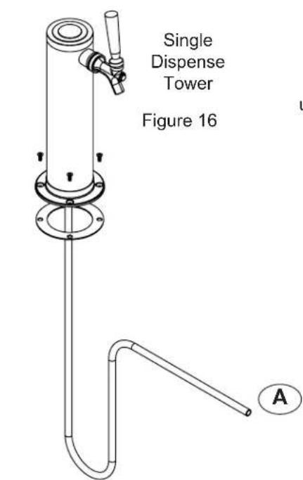


Figure 18
Keg oupler

B
Regulator with red airline
Figure 19
5 Pound CO_2 Tank Figure 20
Connect

to A,etc.
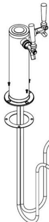
Figure 21 Double Dispense Tower

Figure 22
Hose clamps use for connections

and

Figure 23
Keg Coupler


Keg Coupler
Figure 24

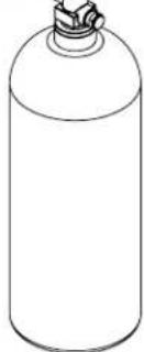
5 Pound CO_2 Tank
Figure 25

USING YOUR BEER DISPENSER

Figure 27

CAUTION
The cutout dimensions shown in Figure 27 are based on a 25% " (64.3 cm) deep counter top. Your counter top may be different than this and require other front to back dimensioning. Refer to the product dimensions on pages 6 and 7 when determining the required dimensions.
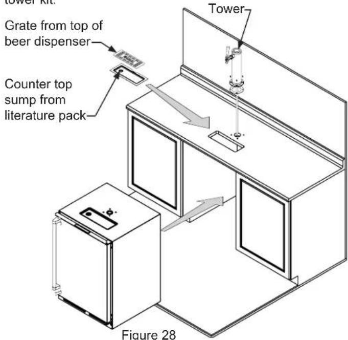
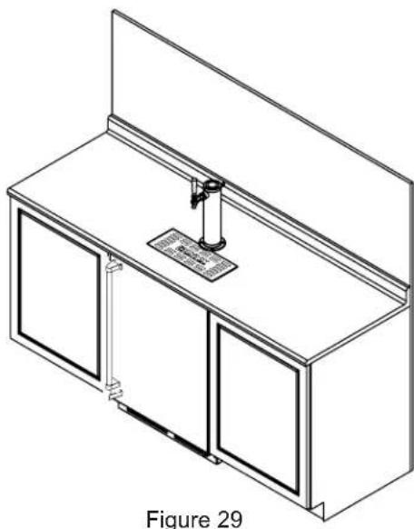
NOTE
Your tower kit may or may not come with a "sit on top" sump option. To use it please follow the instructions in the tower kit.
-
If you are installing your keg refrigerator under a counter you will need to drill 5 holes in the counter top to mount the tower. The first hole is a 112 diameter hole located at the center of the tower for the beer line, locate approximately 1312 (34.3 cm) from the front edge of the counter top (based on a counter top depth of 25516 ). Next drill the 4 tower mounting holes per the dimensions in Figure 27. The hole diameter is dependent on the counter top material and if screw anchors are required. The screws supplied are in the literature pack and are a # 10 × 1 type AB stainless steel screw. Mark and cut the rectangular cutout for the drain sump. After the holes are drilled and the keg refrigerator is in place under the counter top feed the beer line through the tower gasket, the 112 hole in the counter top and the hole in the top of the keg refrigerator. Mount the tower to the counter top with the 4 screws provided. Place the counter top drain sump, from the literature pack, in the rectangular hole with the radius cutout to the rear around the tower and place the grate in the sump.
-
Mount the regulator to the CO_2 tank (connection B). Note that the regulator has left hand threads and has to be turned counterclockwise to tighten. Tighten with the adjustable wrench or the 118 open end wrench.
- Connect the red air line(s) from the regulator to the large air line fitting on the keg coupler with a large hose clamp (connection c).
- Connect the clear beer line from the tower to the small air line fitting on the keg coupler with a small hose clamp (connection A).
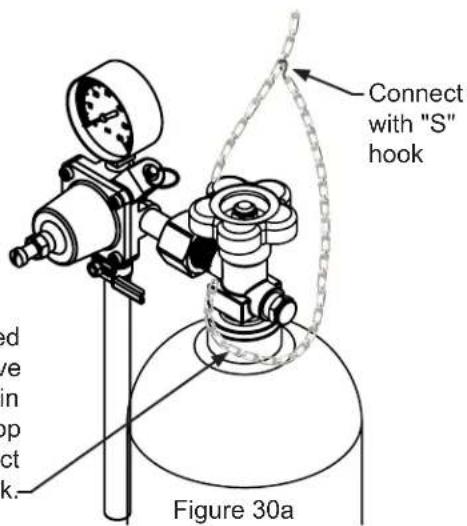
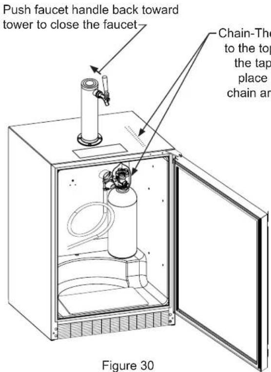
- Locate the CO_2 tank in the corner of the refrigerator as shown in Figure 30 and secure with the chain. Close the faucet handle on the tower.
USING YOUR BEER DISPENSER
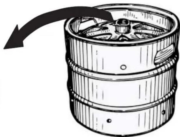
- Hooking up the keg coupler to the keg: Verify the coupler is in the "OFF" position (see Figure 31a). Align the lugs on the keg with the corresponding openings on the keg coupler and turn clockwise until the coupler stops (about 90^ ). Push down and twist the top of the coupler clockwise to allow gas to enter the keg.
Rotate the top of the coupler counterclockwise to extend the coupler to the to the "OFF"position.
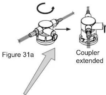
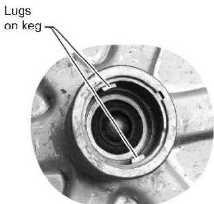
Figure 31b
ure 31
USING YOUR BEER DISPENSER
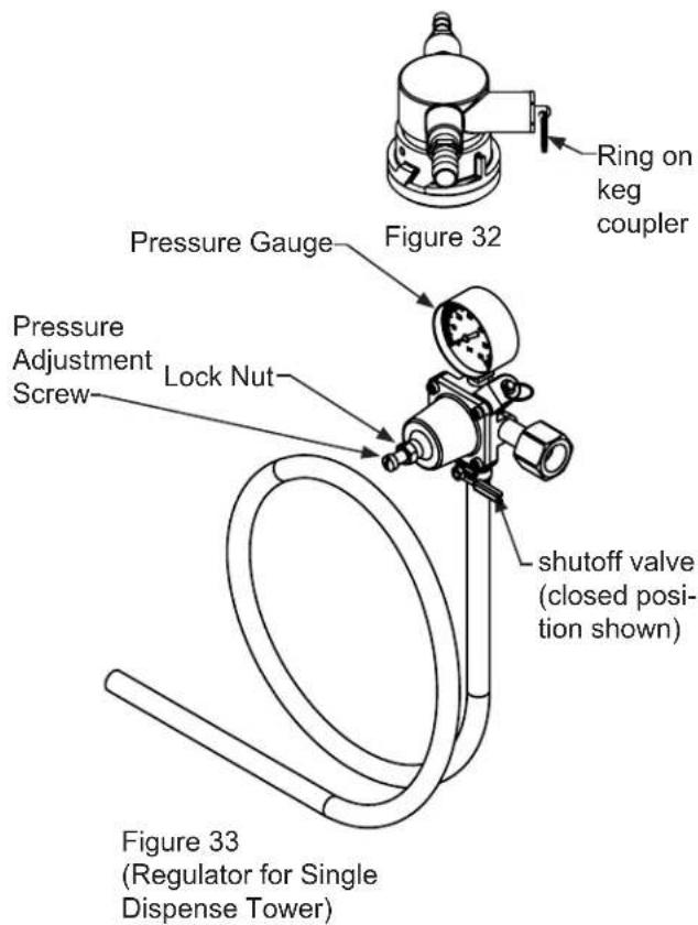
CO_2 Regulator (Single Dispense Tower)
Your beer dispenser comes equipped with a 5 pound CO_2 tank and a single gauge regulator. The gauge reads the pressure being supplied to the beer keg. Follow the procedure below to adjust the pressure to 12 - 14 psi (0.8 to 1 bar) for lager beer or 9 - 12 psi (0.6 to 0.8 bar) for ale's.
To adjust the pressure (Single Gauge):
- Close the shutoff valve at the bottom of the regulator.
- Be sure the faucet handle is closed on the tower (see Figure 30).
- Loosen the lock nut by turning counterclockwise using the 1 / 2" open end wrench until loose, this will allow adjustment of the pressure adjustment screw.
- With the flat bladed screwdriver turn the adjustment screw clockwise to increase the pressure or counterclockwise to decrease the pressure.
- Open the shutoff valve on the bottom of the regulator. The gauge reading may drop but will return very quickly.
- Pull the ring on the keg coupler to allow the gas to flow momentarily.
- Make any fine adjustments if necessary with the adjustment screw.
- Tighten the locknut with the 12 open end wrench by turning clockwise.
CO_2 Regulator (Double Dispense Tower)
Your beer dispenser comes equipped with a 5 pound CO2 tank and a dual gauge regulator. The lower gauge should be reading approximately 750 psi (52 bar) when the tank is properly filled and the tank is not in the refrigerator (at room temperature). The tank will read less when chilled. Use this lower gauge as an indicator of how much CO2 you have left in the tank.
The upper gauge reads the pressure being supplied to the beer keg. Follow the procedure below to adjust the pressure to 12 - 14 psi (0.8 to 1 bar) for lager beer or 9 - 12 psi (0.6 to 0.8 bar) for ale's.
To adjust the pressure (Upper Gauge):
- Close the shutoff valves at the bottom of the regulator.
- Be sure the faucet handle is closed on the tower (see Figure 30).
- Loosen the lock nut by turning counterclockwise using the 12 open end wrench until loose, this will allow adjustment of the pressure adjustment screw.
- With the flat bladed screwdriver turn the adjustment screw clockwise to increase the pressure or counterclockwise to decrease the pressure.
- Open the shutoff valve on the bottom of the regulator. The gauge reading may drop but will return very quickly.
- Pull the ring on the keg coupler to allow the gas to flow momentarily.
- Make any fine adjustments if necessary with the adjustment screw.
- Tighten the locknut with the 12 open end wrench by turning clockwise.
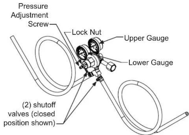
Figure 34
(Regulator for Double Dispense Tower)
CARE AND USE/INSTALLATION
USING YOUR BEER DISPENSER AND CARE AND CLEANING
Drain kit (All Models):
The drain kit is shipped in place and ready to use. To empty: Pull drain hose out of bottle cap, remove bottle from unit, unscrew cap and discard waste and rinse bottle. Reinstall bottle in unit.
Cleaning the drain sump:
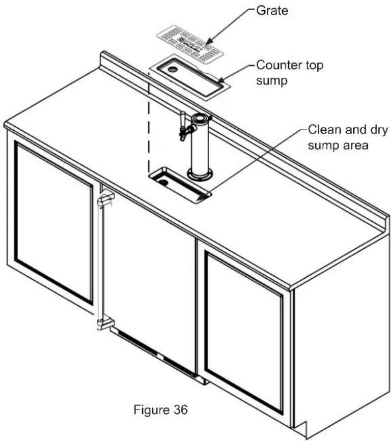
On a free standing beer dispenser remove the grate from in front of the tower, clean with soap and water and dry before reinstalling. Clean the sump area with soapy water and dry. (See Figure 35).
On a built in beer dispenser remove the grate and counter top sump, clean with soap and water and dry before reinstalling. Clean the sump area with soapy water and dry. (See Figure 36).
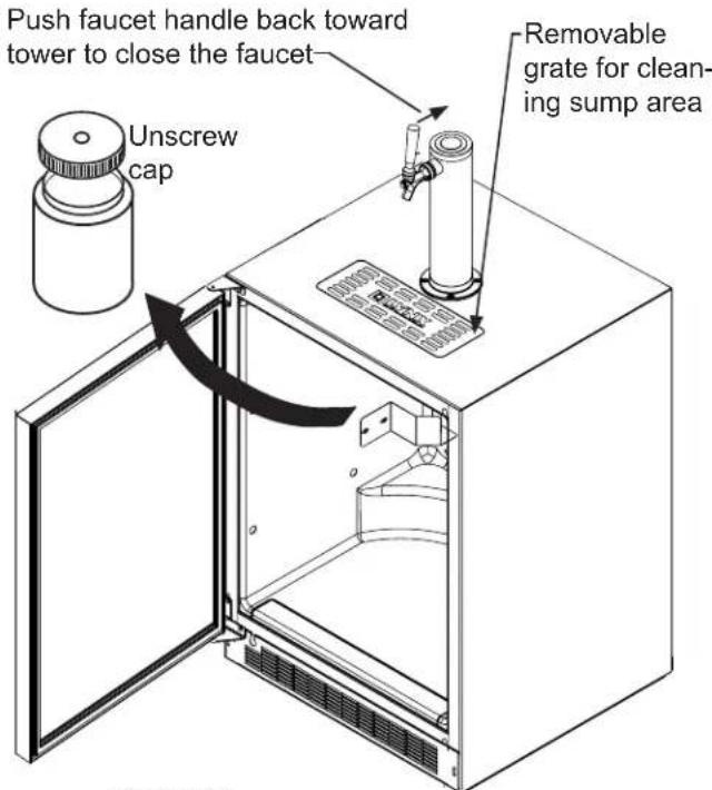
Figure 35
CARE AND CLEANING
Cleaning and Maintaining Dispensing System
The dispensing system needs to be cleaned between usage to prevent spoilage and/or foul taste in your beer.
Keg Coupler Cleaning
Remove the keg coupler from the keg if necessary. Close the gas valve(s) below the regulator, remove both the red gas line(s) and clear beer line(s) from the keg coupler(s) by removing the plastic hose clamps (See Figure 37). Soak and brush the keg coupler in hot water or a sanitizing solution. Rinse thoroughly with clean water. Dry all parts and reassemble.
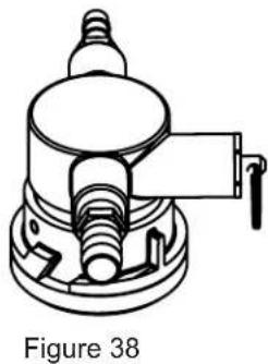
Hose clamps can be released by a lateral movement to the head. Figure 37
Faucet Cleaning
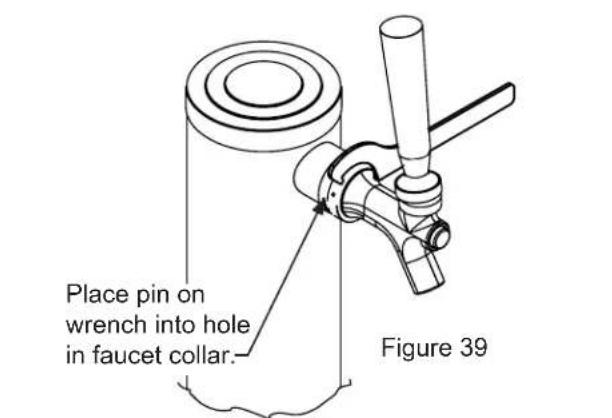
Turn off the gas supply with the shutoff valve(s) under the regulator (see Figure 33 or Figure 34) and open the faucet to relieve the pressure. To remove the faucet from the tower use the spanner wrench provided. Place the pin on the wrench into the hole on the faucet collar and turn clockwise to remove the faucet. (See Figure 39).
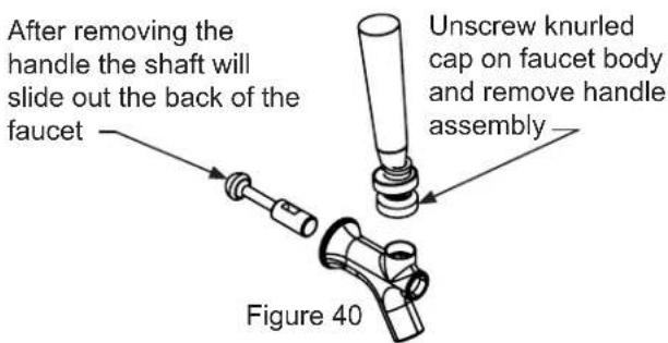
Remove the knurled cap from the faucet body just below the handle and pull the handle assembly from the faucet. This will allow the shaft to be removed from the back of the faucet, see Figure 40.
Soak all faucet parts in hot clear water or a solution of hot water and a sanitizing solution. Do not use soap. Rinse thoroughly with clean water.
Reassemble faucet, assemble faucet to tower (be sure faucet is in off position), and turn on gas valve.
CARE AND CLEANING
Tap Cleaning Kit
This is an optional item (part number 42242373) Kit includes everything to quickly clean tap. Includes cleaning solution, pump, mixing bottle, brush and wrench.
Cleaning the beer line
(using tap cleaning kit 42242373):
With the faucet removed from the tower (see page 17) and the keg coupler removed from the keg (see page 17), place the end of the beer line in a pail or pan. Secure the pump to the tower with the coupler nut provided on the pump assembly. Pump a sanitizer / cleaner through the beer line until clean. Rinse the pump bottle with hot water, and using the pump, flush the beer line 2 or 3 times with clean hot water.
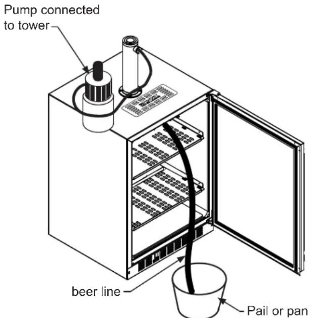
Figure 41
FrontGrille
Be sure that nothing obstructs the required air flow openings in front of the cabinet. At least once or twice a year, brush or vacuum lint and dirt from the front grille area (see page 4).

CAUTION
SHOCK HAZARD: Disconnect electrical power from the appliance before cleaning with soap and water.
Cabinet
The stainless steel cabinet can be washed with either a mild soap and water and thoroughly rinsed with clear water. NEVER use abrasive scouring cleaners. Dry thoroughly with a terry towel.
Interior
Wash interior compartment with mild soap and water. Do NOT use an abrasive cleaner, solvent, polish cleaner or undiluted detergent.
Care of Appliance
Avoid leaning on the door, you may bend the door hinges or tip the appliance.
- Exercise caution when sweeping, vacuuming or mopping near the front of the appliance. Damage to the grille can occur.
- Periodically clean the interior of the appliance as needed.
In the Event of a Power Failure
If a power failure occurs, try to correct it as soon as possible. Minimize the number of door openings while the power is off so as not to adversely affect the appliance's temperature.
Long Term Storage/Winterization
Time to Winterize, when the daily low ambient temperature is at or below 38^ F.

CAUTION
Operating of the unit at ambient temperatures below the recommended Winterization temperature will void your warranty.
- Turn unit off, (see page 8).
- Remove all contents.
- If necessary, move the unit so you can gain access to the rear of the product.
- Unplug the unit from the power outlet.
- It is also recommended that the power to the outlet be turned-off if the circuit is not required for other items during the Winter season.
- Shut-off CO2 tank valve.
- Drain beer line(s)
a. Remove Sankey tap (keg coupler), (see page 17).
b. Remove faucet on tower, (see page 17).
c. Beer lines will gravity drain.
d. Clean beer line tubing, (see page 18).
- Disassemble faucet and clean, (see page 17).
- Soak and clean Sankey Low-Boy tap, (see page 17).
- When cleaning unit pay particular attention to any cracks and crevices that may have accumulated dirt and debris.
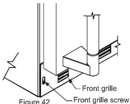
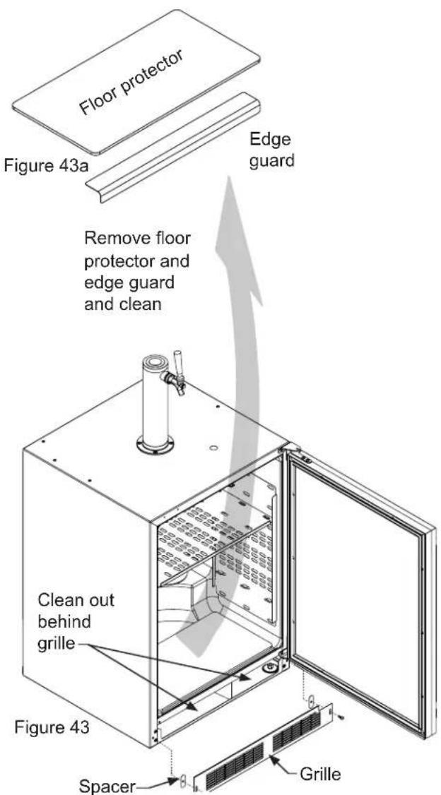
- Remove the front toe-grille, (see Figure 42 and Figure 43), and use a brush and vacuum to clean dirt and debris from beneath the unit.
- Thoroughly clean the toe-grille and re-install on the unit.
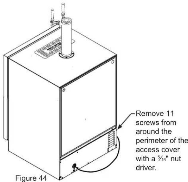
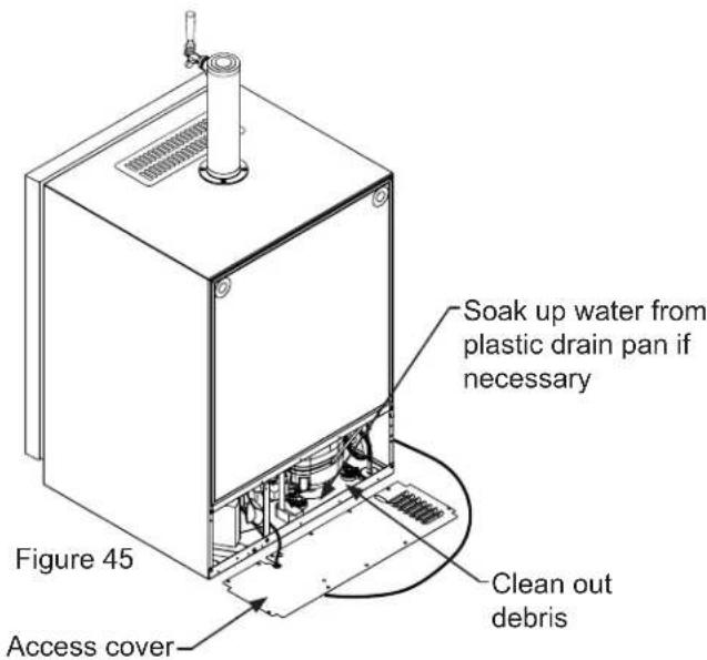
-
Remove the rear access cover, (see Figure 44), and use a brush and vacuum to clean dirt and debris from the machine compartment.
-
If the plastic defrost drain pan located under the compressor contains water, use a sponge to remove as much water as possible
-
Thoroughly clean the rear access cover and re-install on the unit.
- Wipe down all interior surfaces with anti-bacterial cleaner to be followed with clean rinse water to remove any residual chemicals which could cause staining. Do not use any abrasive cleaners or scouring pads.
-
Leave door open and allow to completely dry out before closing door.
-
Remove plastic floor protector and stainless steel lower edge guard to clean underneath.
CARE AND USE/INSTALLATION
CARE AND CLEANING
- Thoroughly clean the door gasket with anti-bacterial cleaner to be followed with clean rinse water to remove any residual chemicals.
- Thoroughly clean the exterior with a cleaner approved for stainless steel. Do not use any abrasive cleaners or scouring pads.
- Any mounting hardware / fasteners that are showing signs of corrosion should be replaced.
- Once the exterior has been thoroughly cleaned, you may want to apply a coating of car wax to help protect against spotting from moisture, dirt, and debris that may accumulate on the surfaces during the Winterization period.
- Do not place a cover on the unit, as this can trap condensation.
After completion of the above, you may choose to store the unit indoors, although this is not required.
Start-Up After Long-Term Storage:
- Connect the unit to electrical power.
- If stored outside, it is recommended that the unit again be thoroughly inspected per the storage instructions above to address any dirt or debris from the weather and/or animals/insects.
- Turn unit on and confirm your desired control settings.
- Allow 24-hrs for the unit to stabilize before loading contents.
STAINLESS STEEL MAINTENANCE AND ENERGY SAVING TIPS
Background
Stainless steel does not stain, corrode, or rust as easily as ordinary steel, but it is not stain or corrosion proof. Stainless steels can discolor or corrode if not maintained properly.
Stainless steels differ from ordinary carbon steels by the amount of chromium present. It is this chromium that provides an invisible protective film on the surface called chrome-oxide. This protective chrome-oxide film on the surface can be damaged or contaminated, which may result in discoloration, staining, or corrosion of the base metal.
Care and Cleaning
Routine cleaning of the stainless steel surfaces will serve to greatly extend the life of your product by removing contaminants. This is especially important in coastal areas which can expose the stainless to severe contaminants such as halide salts, (sodium chloride).
It is strongly recommended to periodically inspect and thoroughly clean crevices, weld points, under gaskets, rivets, bolt heads, and any locations where small amounts of liquid could collect, become stagnant, and concentrate contaminants. Additionally, any mounting hardware that is showing signs of corrosion should be replaced.
Frequency of cleaning will depend upon the installation location, environmental, and usage conditions.
Choosing a Cleaning Product
The choice of a proper cleaning product is ultimately that of the consumer, and there are many products from which to choose. Depending upon the type of cleaning and the degree of contamination, some products are better than others.
Typically the most effective and efficient means for routine cleaning of most stainless steel products is to give the surfaces a brisk rubbing with a soft cloth soaked in warm water and a gentle detergent, or mild mixture of ammonia. Rubbing should, to the extent possible, follow the polish lines of the steel, and always insure thorough rinsing after cleaning.
Although some products are called "stainless steel cleaners," some may contain abrasives which could scratch the surface, (compromising the protective chrome-oxide film), and some many contain chlorine bleach which will dull, tarnish or discolor the surface if not completely removed.
After the stainless surfaces have been thoroughly cleaned, a good quality car wax may be applied to help maintain the finish.
NOTE
Stainless steel products should never be installed, or stored in close proximity to chlorine chemicals.
Whichever cleaning product you chose, it should be used in strict accordance with the instructions of the cleaner manufacturer.
Energy Saving Tips
The following suggestions will minimize the cost of operating your refrigeration appliance.
- Do not install your appliance next to a hot appliance (cooker, dishwasher, etc.), heating air duct, or other heat sources.
- Install product out of direct sunlight.
- Ensure the front grille vents at front of appliance beneath door are not obstructed and kept clean to allow ventilation for the refrigeration system to expel heat.
- Plug your appliance into a dedicated power circuit. (Not shared with other appliances).
- When initially loading your new product, or whenever large quantities of warm contents are placed within refrigerated storage compartment, minimize door openings for the next 12 hours to allow contents to pull down to compartment set temperature.
- Maintaining a relatively full storage compartment will require less appliance run time than an empty compartment.
- Ensure door closing is not obstructed by contents stored in your appliance.
- Allow hot items to reach room temperature before placing in product.
- Minimize door openings and duration of door openings.
- Use the warmest temperature control set temperature that meets your personal preference and provides the proper storage for your stored contents.
- When on vacation or away from home for extended periods, set the appliance to warmest acceptable temperature for the stored contents.
- Set the control to the "off" position if cleaning the appliance requires the door to be open for an extended period of time.
OBTAINING SERVICE AND THE LYNX STORY
If Service is Required:
- If the product is within the first year warranty period please contact your dealer or call Lynx Grills Customer Service at 888-289-5969 for directions on how to obtain warranty coverage in your area.
- In all correspondence regarding service, be sure to give the service/model number, serial number, and proof of purchase.
- If the product is outside the first year warranty period, Lynx Grills Customer Service can provide recommendations of service centers in your area.
- Try to have information or description of nature of the problem, how long the appliance has been running, the room temperature, and any additional information that may be helpful in quickly solving the problem.
- Table C is provided for recording pertinent information regarding your product for future reference.
Table C
| For Your Records | |
| Date of Purchase | |
| Dealer's name | |
| Dealer's Address | |
| Dealer's City | |
| Dealer's State | |
| Dealer's Zip Code | |
| Appliance Serial Number | |
| Appliance Service/Model Number | |
| Date Warranty Card Sent (Must be within 10 days of purchase). | |
The Lynx Story
Lynx began with a vision.
A small group of manufacturing engineers with over a century of collective experience had a dream. They dared to take their extensive commercial manufacturing know-how and create a line of outdoor cooking products that offer commercial elegance and performance to the consumer market.
Lynx has taken the quality, workmanship, service and innovation of the commercial market and incorporated it into the Lynx Professional Grills line of consumer and commercial products. The combination of creative design, superior materials and exceptional craftsmanship elevates Lynx products to a class of their own.
Lynx original commercial products are used every day in restaurants, hotels and theme parks across the USA:
Lynx Satisfied Customers
TGI Fridays
Applebee's
- Houston's
Red Lobster
Hard Rock Café
Wolfgang Puck's
- Cheesecake Factory
Red Robin
Planet Hollywood
Hilton
Hyatt
Four Seasons Marriott Le Meridian
- Sheraton
- Conrad International
Bellagio
New York New York
MGM Grand - Treasure Island
- Mirage
Paris - Venetian
- Excalibur
Mandalay Bay
Riviera
Desert Inn
Hard Rock Hotel - Disney World
TROUBLESHOOTING
Before You Call for Service
If the appliance appears to be malfunctioning, read through this manual first. If the problem persists, check the troubleshooting guide below. Locate the problem in the guide and refer to the cause and its remedy before calling for service. The problem may be something very simple that can be solved without a service call. However, it may be required to contact your dealer or a qualified service technician.

WARNING
Electrocution Hazard
- Never attempt to repair or perform maintenance on the appliance until the main electrical power has been disconnected. Turning the appliance control "OFF" does not remove electrical power from the unit's wiring.
- Replace all parts and panels before operating.

CAUTION
In the unlikely event you lose cooling in your unit, do not unplug the product from the electric supply, but do call a qualified service technician immediately. It is possible that the loss of cooling capacity is a result of excessive frost build-up on the evaporator cooling coil. In this case, removing power to the unit will result in the melting of this excessive quantity of ice, which could generate melt water that exceeds the capacity of the defrost drain system and could result in water damage to your home. The end-user will be ultimately responsible for any water damage caused by prematurely turning the unit off without appropriately managing the excess water run-off.
| Problem Possible Cause | Remedy | |
| Appliance not cold enough(See "Adjusting the temperature" onpage 8) | Control set too warmContent temperature not stabi- lized. | Adjust temperature colder. Al- low 24 hours for temperature to stabilize. |
| Excessive usage or prolonged door openings. | Allow temperature to stabilize for at least 24 hours. | |
| Airflow to front grille blocked. | Airflow must not be obstructed to front grille. See "clearances" on page 4. | |
| Door gasket not sealing properly. | Replace door gasket. | |
| Appliance too cold(See "Adjusting the Temperature" onpage 8) | Control set too cold | Adjust temperature warmer. Allow 24 hours for temperature to stabilize. |
| Door gasket not sealing properly. | Replace door gasket. | |
| Noise or Vibration · Appliance not level | Level appliance, see "Leveling Legs" on page 4. | |
| Fan hitting tube obstruction. | Contact a qualified service techni-cian. | |
| Appliance will not run. · Appliance turned off | Turn appliance on. See "Starting your appliance" on page 8. | |
| Power cord not plugged in. | Plug in power cord. | |
| No power at outlet. | Check house circuit. |
The best outdoor kitchen products come from: Lynx Grills, Inc. 7300 Flores Street Downey, CA 90242
Service: (888)-289-5969 Fax: (562) 299-6789
www.lynxgrills.com
PROFITEZ AU MAXIMUM DE VOTRE
LM24BF
RéFRIGÉRATEUR EXTÉRIEURE / DISTRIBUTEUR DEBREUVAGE
ENTRETIEN ET UTILISATION / INSTALLATION
CONTENU
Contenu
DIMENSIONS DU PRODUIT
| MODELE | DIMENSIONS D'OUVERTURE BRUTE DIMENSIONS D'ARMOIRE | ||||||||
| «A» «B» «C» «D» «E» «F» «G» | «H» «J» | ||||||||
| LM24BF | 24 po (61 cm) | **34 po to 35 po (86,4 to 88,9 cm) | * | 23¾ po (60,7 cm) | 33¾ po to 34¾ po (85,7 to 88,3 cm) | 23½³/₂ po (60,2 cm) | 26¾ po (67,9 cm) | 46½³/₂ po (117,9 cm) | 26¾ po (67,9 cm) |
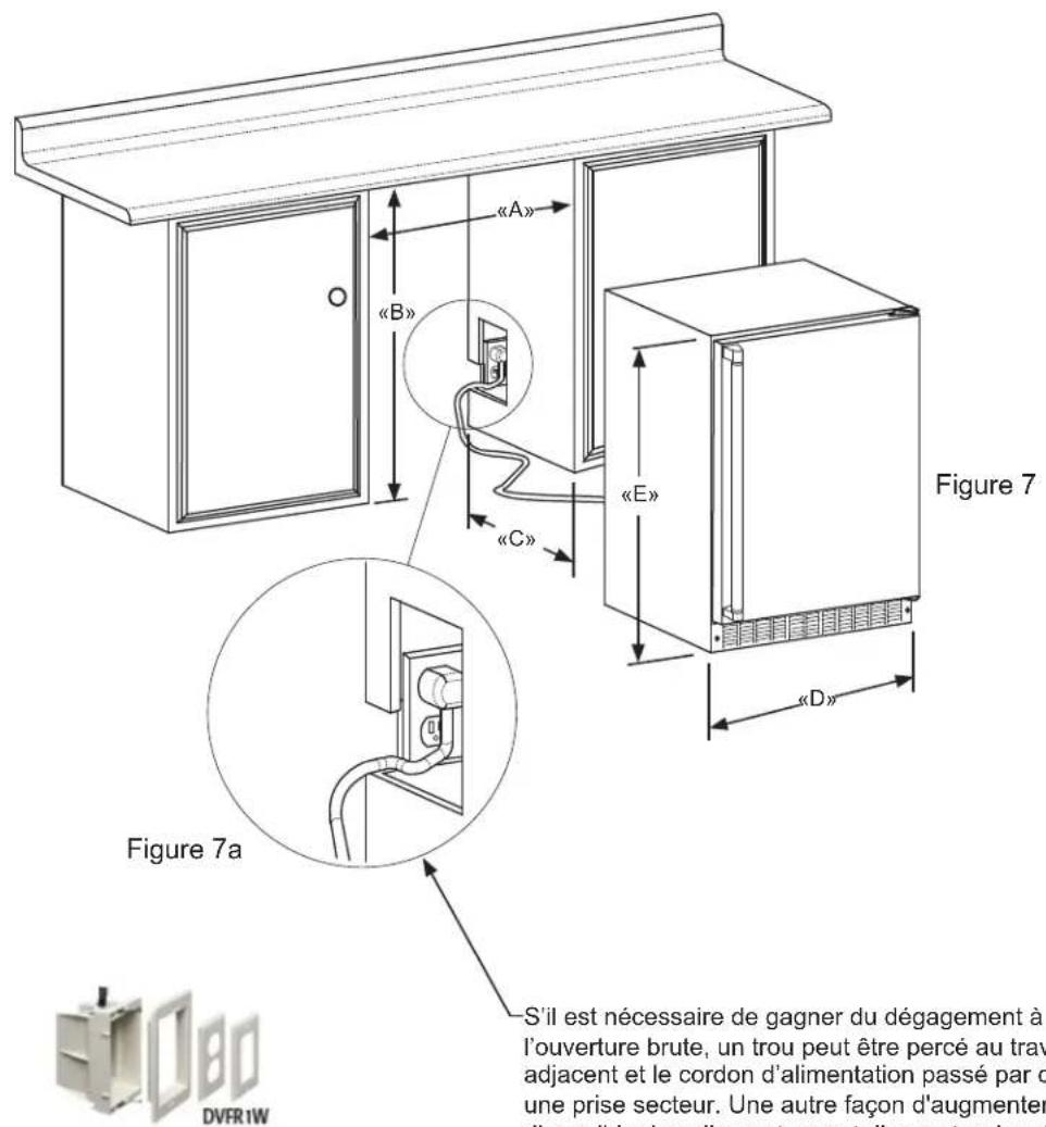
Figure 8
DIMENSIONS DU PRODUIT
| MODELE | DONNÉES DE PRODUIT | |
| BESOINS ÉLECTRIQUES # | POIDS DU PRODUIT | |
| LM24BF 115V | /60Hz/15A | 140 lb (63,6 kg) |
TGI Fridays
Applebee's
- Houston's
Red Lobster
Hard Rock Café
Wolfgang Puck's
- Cheesecake Factory
Red Robin
Planet Hollywood
Hilton
Hyatt
Four Seasons Marriott Le Meridian
- Sheraton
- Conrad International
Bellagio
New York New York
MGM Grand - Treasure Island
Mirage
Paris - Venetian
- Excalibur
Mandalay Bay
Riviera
Desert Inn
Hard Rock Hotel - Disney World
DéPANNAGE
DIMENSIONES DEL PRODUCTO
| MODELO | DIMENSIONES DE LA ABERTURA DE INSTALLACION pulgadas (cm) DIMEN | SINonas DEL GABINETE pulgadas (cm) | |||||||
| "A" | "B" | "C" | "D" | "E" | "F" | "G" | "H" | "J" | |
| LM24BF | 24" | **34" to 35" | * | 23¾" | 33¾" to 34¾" | 23½¾" | 26¼" | 46½¾" | 26¾" |
| (61 cm) | (86,4 to 88,9 cm) | (60,7 cm) | (85,7 to 88,3 cm) | (60,2 cm) | (67,9 cm) | (117,9 cm) | (67,9 cm) | ||
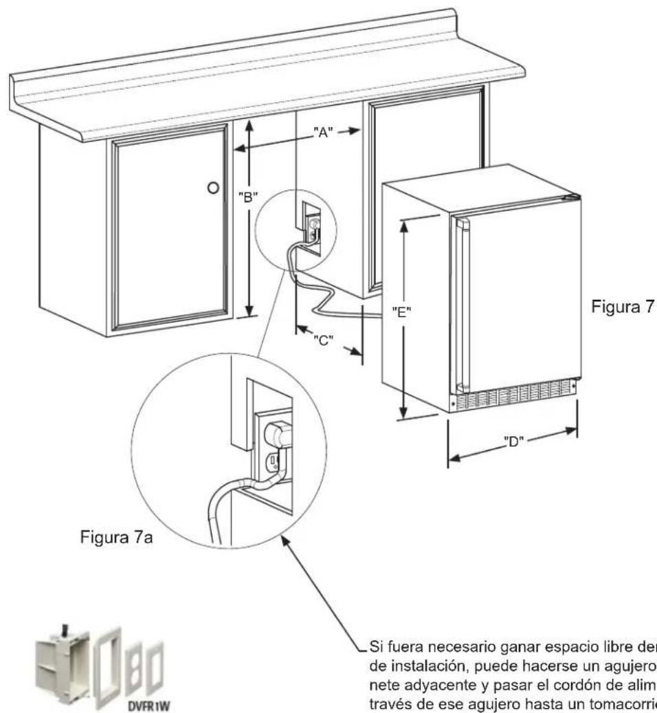
Figura 8
DIMENSIONES DEL PRODUCTO
| MODELO | DATOS DEL PRODUCTO | |
| REQUISITOS ELECTRICOS # | PESO DEL PRODUCTO | |
| LM24BF 115V | /60Hz/15A | 140 lbs (63,6 kg) |
TGI Fridays
Applebee's
- Houston's
Red Lobster
Hard Rock Café
Wolfgang Puck's
- Cheesecake Factory
Red Robin
Planet Hollywood
Hilton
Hyatt
Four Seasons Marriott Le Meridian
- Sheraton
- Conrad International
Bellagio
New York New York
MGM Grand - Treasure Island
Mirage
Paris - Venetian
- Excalibur
Mandalay Bay
Riviera
Desert Inn
Hard Rock Hotel - Disney World

- Important Safety Instructions
- Recognize Safety Symbols, Words, and Labels.
- WARNING
- CAUTION
- NOTE
- UNPACKING YOUR APPLIANCE
- EXCESSIVE WEIGHT HAZARD
- Remove Interior Packaging
- Important
- Note to Customer
- Warranty Registration
- WARNING - Help Prevent Tragedies
- INSTALLING YOUR APPLIANCE
- Select Location
- Cabinet Clearance
- Leveling Legs
- FrontGrille
- Electrical Shock Hazard
- Electrical Connection
- PRODUCT DIMENSIONS
- USING YOUR ELECTRONIC CONTROL
- Starting Your Refrigerator
- Turning Your Refrigerator ON or OFF
- Set temperature
- Beverage Dispenser Operation
- Alarms
- Alarm Mute
- USING YOUR BEVERAGE DISPENSER
- Shelving
- Tap Equipment and Assembly
- Your dispensing kit includes the following parts:
- Tools required for installation:
- USING YOUR BEER DISPENSER
- Single Dispense Tower Kit Double Dispense Tower Kit
- CO_2 Regulator (Single Dispense Tower)
- To adjust the pressure (Single Gauge):
- CO_2 Regulator (Double Dispense Tower)
- To adjust the pressure (Upper Gauge):
- USING YOUR BEER DISPENSER AND CARE AND CLEANING
- Drain kit (All Models):
- Cleaning the drain sump:
- CARE AND CLEANING
- Cleaning and Maintaining Dispensing System
- Keg Coupler Cleaning
- Faucet Cleaning
- Tap Cleaning Kit
- Cleaning the beer line
- (using tap cleaning kit 42242373):
- Cabinet
- Interior
- Care of Appliance
- In the Event of a Power Failure
- Long Term Storage/Winterization
- Start-Up After Long-Term Storage:
- STAINLESS STEEL MAINTENANCE AND ENERGY SAVING TIPS
- Background
- Choosing a Cleaning Product
- Energy Saving Tips
- The following suggestions will minimize the cost of operating your refrigeration appliance.
- OBTAINING SERVICE AND THE LYNX STORY
- If Service is Required:
- The Lynx Story
- Lynx Satisfied Customers
- TROUBLESHOOTING
- Before You Call for Service
- Electrocution Hazard
- PROFITEZ AU MAXIMUM DE VOTRE
- CONTENU
- DIMENSIONS DU PRODUIT
- DéPANNAGE
- DIMENSIONES DEL PRODUCTO
Brand : LYNX
Model : LM24BFL
Category : Fridge