S125PF1E5A - Air-conditioner PANASONIC - Free user manual and instructions
Find the device manual for free S125PF1E5A PANASONIC in PDF.

User questions about S125PF1E5A PANASONIC
0 question about this device. Answer the ones you know or ask your own.
Ask a new question about this device
Download the instructions for your Air-conditioner in PDF format for free! Find your manual S125PF1E5A - PANASONIC and take your electronic device back in hand. On this page are published all the documents necessary for the use of your device. S125PF1E5A by PANASONIC.
USER MANUAL S125PF1E5A PANASONIC
Operating Instructions Air Conditioner
Low Silhouette Ducted (F1 type)
natural_image
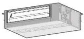
3D rendering of a rectangular air conditioner unit with ventilation grille (no text or symbols)Ceiling (T2 type)
natural_image
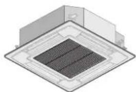
3D rendering of a square industrial or structural component with a central grid pattern (no text or symbols visible)4-Way Cassette (U1 type)
Model No.
INDOOR UNIT
4-Way Cassette (U1 type)
| S-36PU1E5A | S-71PU1E5A |
| S-45PU1E5A | S-100PU1E5A |
| S-50PU1E5A | S-125PU1E5A |
| S-60PU1E5A | S-140PU1E5A |
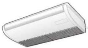
Ceiling (T2 type)
| S-36PT2E5A | S-71PT2E5A |
| S-45PT2E5A | S-100PT2E5A |
| S-50PT2E5A | S-125PT2E5A |
| S-60PT2E5A | S-140PT2E5A |
Low Silhouette Ducted (F1 type)
| S-36PF1E5A | S-71PF1E5A |
| S-45PF1E5A | S-100PF1E5A |
| S-50PF1E5A | S-125PF1E5A |
| S-60PF1E5A | S-140PF1E5A |
OUTDOOR UNIT
Single Split (Single-phase) PE1 Type
| — | U-71PE1E5A |
| — | U-100PE1E5A |
| U-50PE1E5 | U-125PE1E5A |
| U-60PE1E5A | U-140PE1E5A |
Single Split (3-phase) PE1 Type
Single Split (Single-phase) PEY1 Type
| — | U-71PEY1E5 |
| — | U-100PEY1E5 |
| — | U-125PEY1E5 |
| U-60PEY1E5 | — |
Single Split (3-phase) PEY1 Type
| — | — |
| — | U-100PEY1E8 |
| — | U-125PEY1E8 |
| — | U-140PEY1E8 |
ENGLISH 2 \~ 9 Before operating the unit, read these operating instructions thoroughly and keep them for future reference.
Thank you for purchasing this Panasonic product. This product is a commercial air conditioner indoor unit. Installation Instructions attached.
Contents
● Safety Precautions ...... 2
● Precautions for Use....4
- Names of Parts....5
• Operation Mechanism....5
- Adjusting Airflow Direction....6
- Adjusting airflow direction for multiple indoor units....7
● Maintenance 8
• Before Requesting Services....8
● Troubleshooting....9
- Specifications....74
- Indoor unit....74
• Outdoor unit 76
• Corresponding language table....78
Product Information
If you have problems or questions concerning your Air Conditioner, you will need the following information. Model and serial numbers are on the nameplate on the bottom of the cabinet.
Model No.
Serial No.
Date of purchase
Dealer's address
Phone number
Safety Precautions
The following symbols used in this manual, alert you to potentially dangerous conditions to users, service personnel or the appliance:

WARNING
This symbol refers to a hazard or unsafe practice which can result in severe personal injury or death.

CAUTION
This symbol refers to a hazard or unsafe practice which can result in personal injury or product or property damage.

Prohibited matters

Matters to be observed
- Read these Operating Instructions carefully before using this air conditioner. If you still have any difficulties or problems, consult your dealer for help.
- This air conditioner is designed to give you comfortable room conditions. Use this only for its intended purpose as described in these Operating Instructions.

WARNING

Confir rm to authorized dealer or specialist on usage of specifi ed refrigerant type. Using of refrigerant other than the specifi ed type may cause product damage, burst and injury etc.
This air conditioner has no ventilator for intaking fresh air from outdoors. You must open doors or windows frequently when you use gas or oil heating appliances in the same room, which consume a lot of oxygen from the air. Otherwise there is a risk of suffocation in an extreme case.

Never use or store gasoline or other fl ammable vapor or liquid near the air conditioner — it is very dangerous.
Do not use this appliance in a potentially explosive atmosphere.
Never touch the unit with wet hands.
Do not insert your fingers or other objects into the air conditioner indoor or outdoor unit, rotating parts m cause injury.


Refrigerant gas leakage may cause fi re.
For safety, be sure to turn the air conditioner off and also to disconnect the power before cleaning or servicing.
Pull off the power plug from a receptacle, or switch off the breaker, or switch off the power disconnecting mean to isolate the air conditioner from the main power supply in case of emergency.

Do not clean inside the indoor and outdoor units by users. Engage authorized dealer or specialist for cleaning.
In case of malfunction of this appliance, do not repair by yourself. Contact to the sales dealer or service dealer for a repair.

Provide a power outlet to be used exclusively for each unit, and a power supply disconnect, circuit breaker and earth leakage breaker for overcurrent protection should be provided in the exclusive line.
Provide a power outlet exclusively for each unit, and full disconnection means having a contact separation in all poles must be incorporated in the fixed wiring in accordance with the wiring rules.
To prevent possible hazards from insulation failure, the unit must be grounded.


Do not use modified cord, joint cord, extension cord or unspecified cord to prevent overheating and fi re.

Stop using the product when any abnormality/failure occurs and disconnect the power plug or turn off the power switch and breaker. (Risk of smoke/fi re/electric shock) Examples of abnormality/failure:
• The ELCB trips frequently.
- The product sometimes does not start when turned on.
- The power is sometimes disconnected when the cord is moved.
- Burnt odor or abnormal noise is detected during operation.
• The body is deformed or abnormally hot.
• Water leaks from the indoor unit.
• Power cord or plug becomes abnormally hot.
• Fan speed cannot be controlled.
• The unit stops running immediately even if it is switched on for operation.
- The fan does not stop even if the operation is stopped.
Contact immediately your local dealer for maintenance/repair.

Do not sit or step on the unit. You may fall down accidentally.

CAUTION

This appliance is intended to be used by expert or trained users in shops, in light industry and on farms, or for commercial use by lay persons.
This appliance can be used by children aged from 8 years and above and persons with reduced physical, sensory or mental capabilities or lack of experience and knowledge if they have been given supervision or instruction concerning use of the appliance in a safe way and understand the hazards involved.
Keep the fire alarm and the air outlet at least 1.5m away from the unit.
Do not cool or heat the room too much if babies or invalids are present.
ENGLISH

Do not turn the air conditioner on and off from the power mains switch. Use the ON/OFF operation button.
Do not stick anything into the air outlet of the outdoor unit. This is dangerous because the fan is rotating at high speed.

Do not touch the air inlet or the sharp aluminum fi ns of the outdoor unit. You may get injured.

Do not stick any object into the FAN CASE. You may be injured and the unit may be damaged.
NOTICE
- The compressor may occasionally stop during thunderstorms. This is not a mechanical failure. The unit automatically recovers after a few minutes.
- The English text is the original instructions. Other languages are translation of the original instructions.
Important Information Regarding The Refrigerant Used
This product contains fl uorinated greenhouse gases covered by the Kyoto Protocol. Do not vent gases into the atmosphere.
Refrigerant type: R410A
GWP ^(1) value: 1975
(1) GWP = global warming potential
Periodical inspections for refrigerant leaks may be required depending on European or local legislation. Please contact your local dealer for more information.
Precautions for Use
Installation
● This air conditioner must be installed properly by qualified installation technicians in accordance with the Installation Instructions provided with the unit.
- Before installation, check that the voltage of the electric supply in your home or offi ce is the same as the voltage shown on the nameplate.

WARNING
Avoid the following locations for installation.
- Locations where smoke or combustible gas exists.
Also locations of extremely high temperature such as a greenhouse. - Locations where excessively high heat-generating objects are placed.
Attention:
- Avoid installing the outdoor unit where salty sea water can splash directly onto it or in sulphurous air near a spa. (To protect the air conditioner from heavy corrosion)
Wiring
● All wiring must conform to the local electrical codes.
(Consult your dealer or a qualifi ed electrician for details.)
● Each unit must be properly grounded with a ground (or earth) wire or through the supply wiring.
● Wiring must be done by a qualified electrician.
Operation Preparation
Turn the power mains on 5 hours before the start of operation.
(For warm-up)
- Leave the power mains ON for continuous use.
NOTE
Pull off the power plug from a receptacle, or switch off the breaker, or switch off the power disconnecting mean to isolate the air conditioner from the main power supply when not in use for a long time.
Operation Condition
Use this air conditioner under the following temperature range.
■ Indoor temperature range:
Cooling mode 14°C \~ 25°C (*WBT) / 18°C \~ 32°C (*DBT)
Heating mode 16°C \~ 30°C (*DBT)
■ Outdoor temperature range:
Cooling mode -15°C \~ 46°C (*DBT)
-10°C \~ 43°C (*DBT)*1
Heating mode -20°C \~ 18°C (*WBT) / -20°C \~ 24°C (*DBT)
-15^ 18^ (*WBT)/ -15^ 24^ (*DBT)*1
*DBT: Dry bulb temperature
*WBT: Wet bulb temperature
*1 When connecting U-60PEY1E5, U-71PEY1E5,
U-100PEY1E5, U-100PEY1E8, U-125PEY1E5,
U-125PEY1E8, U-140PEY1E8
These symbols on the products, packaging, and/or accompanying documents mean that used electrical and electronic products and batteries should not be mixed with general household waste.
For proper treatment, recovery and recycling of old products and used batteries, please take them to applicable collection points, in accordance with your national legislation and the Directives 2002/96/EC and 2006/66/EC. By disposing of these products and batteries correctly, you will help to save valuable resources and prevent any potential negative effects on human health and the environment which could otherwise arise from inappropriate waste handling.
For more information about collection and recycling of old products and batteries, please contact your local municipality, your waste disposal service or the point of sale where you purchased the items.
Penalties may be applicable for incorrect disposal of this waste, in accordance with national legislation.
For business users in the European Union If you wish to discard electrical and electronic equipment, please contact your dealer or supplier for further information.
[Information on Disposal in other Countries outside the European Union]
These symbols are only valid in the European Union. If you wish to discard these items, please contact your local authorities or dealer and ask for the correct method of disposal.
![PANASONIC S125PF1E5A - [Information on Disposal in other Countries outside the European Union] - 1](/content/2026/03/484551/images/ad772dc10c4fd41783a66b885f92e702d294e26642bb4ae3b331084911318960.jpg)
Note for the battery symbol (bottom two symbol examples):
This symbol might be used in combination with a chemical symbol. In this case it complies with the requirement set by the Directive for the chemical involved.
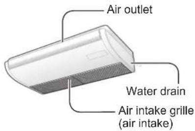
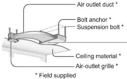
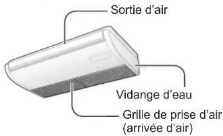
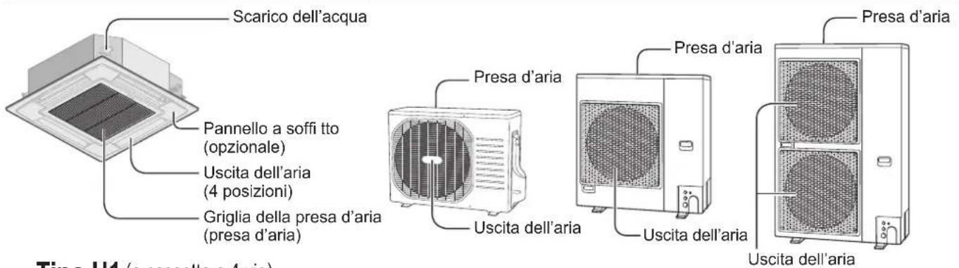
Names of Parts
text_image
Water drain Ceiling panel (optional) Air outlet (4 locations) Air intake grille (air intake)U1 type (4-Way Cassette)
text_image
Air outlet Water drain Air intake grille (air intake)T2 type (Ceiling)
text_image
Air outlet duct * Bolt anchor * Suspension bolt * Ceiling material * Air-outlet grille * * Field suppliedF1 type (Low Silhouette Ducted)
text_image
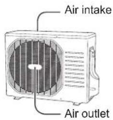
Air intake Air outlet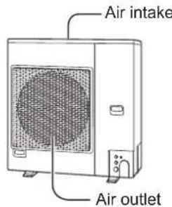
text_image
Air intake Air outlet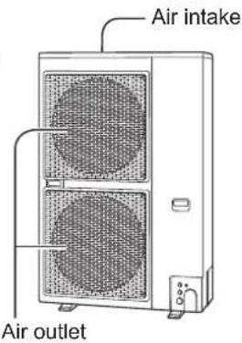
text_image
Air intake Air outletPE1 (50 type)
PEY1 (60, 71 type)
PE1 (60, 71 type)
PEY1 (100, 125 type)
PE1 (100, 125, 140 type)
PEY1 (140 type)
Optional
Wireless Remote Controller Timer Remote Controller
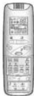
Model No.
CZ-RWSU2 (U1 type)
CZ-RWST3 (T2 type)
CZ-RWSC3
(For all indoor units)
Model No. CZ-RTC2
For all indoor units
High-spec Wired Remote Controller
Model No. CZ-RTC3
For all indoor units
Read the operating instructions included with the Remote Controller.
Operation Mechanism
■ Heating performance
- Since this air conditioner utilizes outside air for heating, its heating performance deteriorates as outside temperature decreases.
(Due to heat pump system)
→In that case, use another heating appliance.
■ Defrosting
● This appliance may start defrosting operation to melt frost formed in the outdoor unit.
①Defrosting starts: The indoor unit fan stops (or the speed becomes extremely slow).
→"○" (STANDBY) appears.
② Heating operation resumes after several minutes: The indoor unit fan remains stopped (or it will run at a very slow speed) until the indoor heat exchanger coil warms up sufficiently.
→ "○" (STANDBY) is shown.
③Defrosting is complete: The indoor unit fan starts operation.
→ "○" (STANDBY) disappears.
■ "DRY" operation
- Once the room temperature reaches the level that was set, the outdoor unit repeats the cycle of turning on and off automatically.
- When the outdoor unit is turned off, the indoor unit fan will stop, too.
(To prevent the humidity in the room from rising again) - When the room temperature is more likely to reach the level that was set, the fan speed is set to "breeze" (light wind) automatically.
- "DRY" operation is not possible if the outdoor temperature is 15 °C or less.
■ Should the power failure occurs while the unit is running
When the unit automatically resumes operation after temporary power failure, it uses the same settings before the power was cut off.
Adjusting Airflow Direction
This section is described in the instruction manual supplied with the timer remote controller (CZ-RTC2).
Regarding the High-spec Wired Remote Controller (CZ-RTC3), refer to the Operating Instructions supplied with the model CZ-RTC3.
Adjusting the upward and downward motion of airflow direction (U1 and T2 types only)
■ Using the timer remote controller
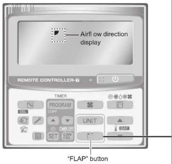
text_image
Airfl ow direction display REMOTE CONTROLLER TIMER PROGRAM COPY UNIT SET CAN CEL "FLAP" button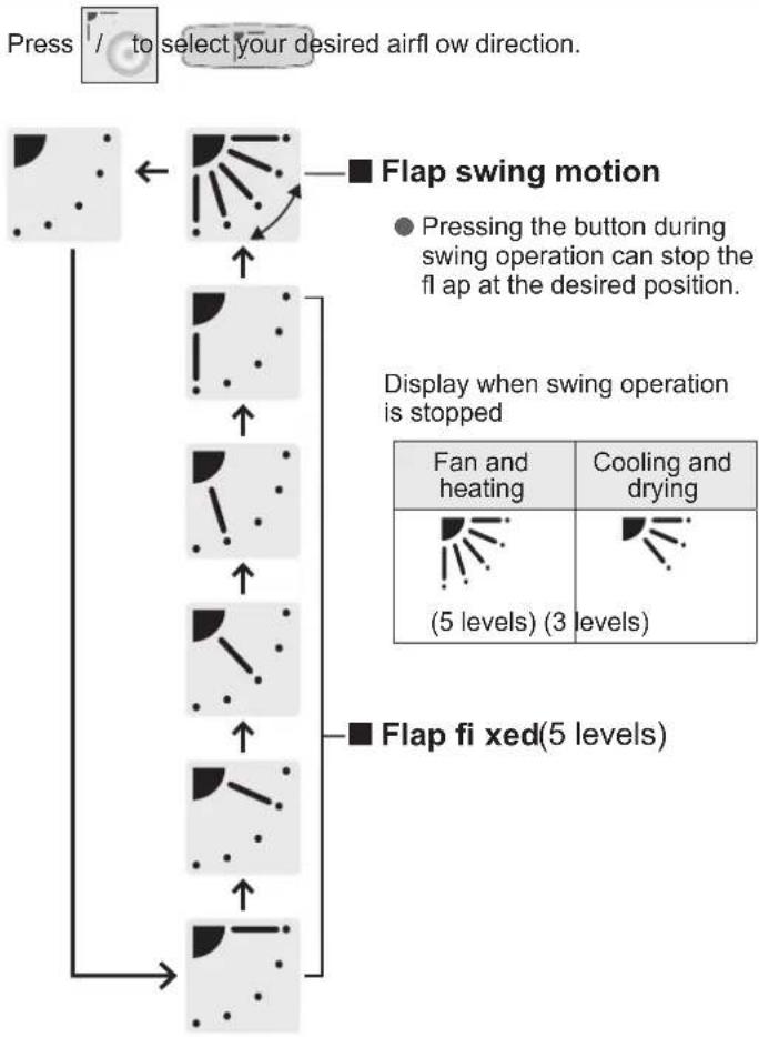
flowchart
graph TD
    A["Press / to select your desired airflow direction."] --> B["Flap swing motion"]
    B --> C["Pressing the button during swing operation can stop the fl ap at the desired position."]
    C --> D["Display when swing operation is stopped"]
    D --> E["Fan and heating (5 levels) (3 levels)"]
    D --> F["Cooling and drying (5 levels)"]
    E --> G["Flap fi xed (5 levels)"]
    F --> G
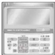
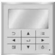
■ Using the wireless remote controller
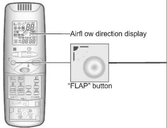
text_image
Airfly ow direction display "FLAP" buttonRecommended vertical airflow direction
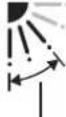
- Set the fl ap to the downward position for heating operation. (With the upward setting, warm air cannot reach the fl oor.)
- Set the fl ap to the upward position for cooling operation. (With the downward setting, condensation may drip on to the fl oor.)
U1, T2 type
| HEAT COOL / DRY FAN | ||
 Recommended Recommended | 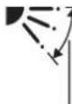 Recommended Recommended | [SHAX]I o this position |
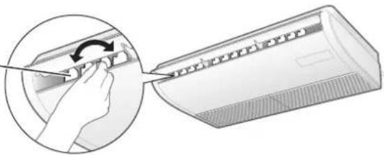
■Adjusting the horizontal airflow direction
(Manual: T2 type only)
Move the horizontal airflow vanes by hand for adjustment.
natural_image
Illustration of a hand using a tool to adjust or install a wall-mounted air conditioner (no text or symbols visible)Adjusting airflow direction for multiple indoor units (Timer remote controller only)
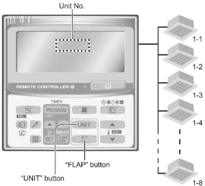
When operating multiple indoor units using 1 remote controller, airflow direction can be adjusted for indoor each unit individually or all units at the same time.
text_image
Unit No. REMOTE CONTROLLER TIMER PROGRAM COPY SET CAN CEL UNIT "FLAP" button "UNIT" button 1-1 1-2 1-3 1-4 1-8● Maximum of 8 indoor units can be connected.
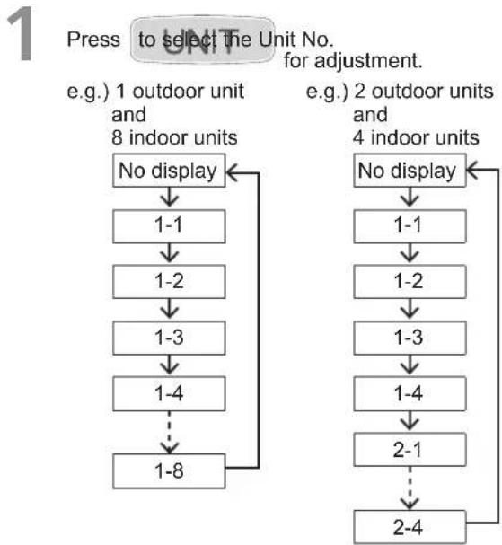
■ When setting the airflow direction of each indoor unit individually
flowchart
graph TD
    A["Press to select the Unit No. for adjustment."] --> B["e.g.) 1 outdoor unit and 8 indoor units"]
    B --> C["No display"]
    C --> D["1-1"]
    D --> E["1-2"]
    E --> F["1-3"]
    F --> G["1-4"]
    G --> H["1-8"]
    H --> I["End"]

    J["e.g.) 2 outdoor units and 4 indoor units"] --> K["No display"]
    K --> L["1-1"]
    L --> M["1-2"]
    M --> N["1-3"]
    N --> O["1-4"]
    O --> P["2-1"]
    P --> Q["2-4"]
    Q --> R["End"]
2 Press to select your desired airflow direction.
■ When setting the airflow direction of all indoor units at the same time
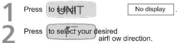
text_image
1 Press to select 2 Press to select your desired airfl ow direction. No display.Attention:
● Never use your hands to move the flap (vertical airflow flap) controlled using the remote controller.
Note
- When the air conditioner is turned off, the flap automatically moves toward the direction of closing.
● The flap (vertical airflow flap) moves to the upward position during standby operation for heating. - The swing operation starts after the standby operation has finished, but "Swing" is indicated on the remote controller even during the standby operation.
Tips for Energy Saving
Avoid
- Do not block the air intake and outlet of the unit. (If either is obstructed, the unit will not function well, causing malfunction.)
● During cooling operation, use sunshades, blinds or curtains to prevent direct sunlight from entering the room.
Do
● Always keep the air fi liter clean.
(A clogged fi liter will impair the performance of the unit.)
→ "Maintenance" (P.8)
● To prevent conditioned air from escaping, keep windows, doors and any other openings closed.
Maintenance
Indoor unit (e.g. U1 type)
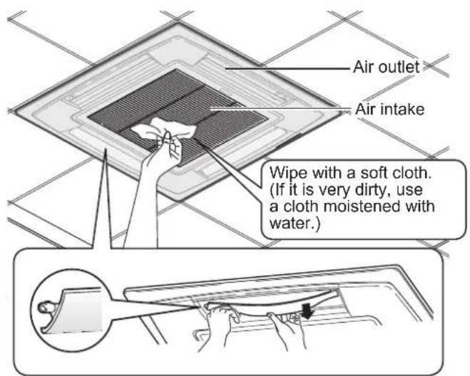
text_image
Air outlet Air intake Wipe with a soft cloth. (If it is very dirty, use a cloth moistened with water.)Wash the fl ap for the air outlet with water.
(U1 type only)
- Be sure to stop the operation beforehand.
• After washing with water, allow it to dry, and then attach it with the arrow facing outward.
WARNING
- For safety, be sure to turn the air conditioner off and disconnect the power before cleaning.
(Otherwise, electric shock or injury may result because the fan is rotating at high speed.) - Do not pour water on the indoor unit. (This may damage the internal components and cause an electric shock hazard.)
CAUTION
● Never use solvents or harsh chemicals. Also, do not wipe plastic parts using very hot water.
(This may cause deformation or change in colour.)
- Some metal edges and fins are sharp. Be careful when you clean those parts.
(Injury may result.)
- Use a firm stool or ladder when cleaning an indoor unit installed in high locations.
● The internal coil and other components of the outdoor unit must be cleaned periodically.
- Consult your dealer or service center.
Before Requesting Services
| Symptom Cause Action | ||
| The air conditioner does not operate although the power is turned on. | Power failure or after power failure Press the power ON/OFF button on the remote controller. | |
| The operation (power) button is turned off. | · If the breaker is turned off, turn the power on.· If the breaker has been tripped, consult your dealer without turning it on. | |
| Fuse blow out. Contact your dealer. | ||
| Poor cooling or heating performance | The air intake or air outlet of indoor and outdoor units is clogged with dust. | Remove the dust. |
| The wind speed switch is set to “Low”. Change to “High” or “Strong”. | ||
| Improper temperature settings | See “Tips for Energy Saving”. (P.7) | |
| The room is exposed to direct sunlight in cooling mode. | ||
| Doors or windows are open. | ||
| The air fi Iter is clogged. See “Maintenance”. (P.8) | ||
| Too many heat sources in the room in cooling mode. | Use minimum heat sources and in a short time. | |
| Too many people in the room in cooling mode. | Lower the temperature setting or change to “High” or “Strong”. | |
If your air conditioner does not work properly even after checking each item of "Before Requesting Services" and "Troubleshooting"
- Stop the operation immediately and turn the power off. Then contact your dealer and report the serial number and symptom. You also report if the inspection mark ⚠️ and the letters E, F, H, L, P in combination with numbers appear on the LCD of the remote controller.
● Never repair the air conditioner by yourself since it is very dangerous for you to do so.
Troubleshooting
Check before consulting or requesting services.
| Symptom Cause / Action | ||
| Noise | Sound like streaming water is heard during operation or after operation. | Sound of refrigerant liquid fl owing inside unitSound of drainage water through drain pipe |
| Cracking noise is heard during operation or when operation stops. | ||
| Discharged air smells during operation. | Sound due to temperature changes of parts | |
| Indoor odor components, cigarette odor and cosmetic odor accumulated in the air conditioner and its air is discharged.The unit inside is dirty.(Contact your dealer.) | ||
| Dewdrops accumulate near the air outlet during cooling operation. | Internal moisture is cooled by cool wind and accumulates as dewdrops. | |
| Fog occurs during cooling operation. | If the air conditioner has been installed at places such as restaurants where large amounts of oil mist exist, cleaning is necessary because the unit inside (heat exchanger) is dirty.(Contact your dealer.) | |
| Fog occurs during heating operation. | Defrost operation is in process. | |
| The fan is rotating for a while even though operation stops. | Fan rotation makes operation smooth.The fan may rotate to dry the heat exchanger depending on the setting. | |
| Airfl ow direction | Airfl ow direction changes while operating.Airfl ow direction cannot be set.Airfl ow direction cannot be changed. | When air discharge temperature is low during heating operation, or during defrost operation, horizontal wind flow is made automatically.The fl ap position may be set individually.(U1 type) |
| The fl ap moves several times after the direction is changed. | The fl ap moves to the standard position once, and then turns to the set airfl ow direction. | |
| Dust is discharged. | Dust accumulated inside the indoor unit is discharged. | |
| At the initial high-speed operation, the fan sometimes rotates faster than the setting speed.(3 to 30 minutes) | This is for operation check in order to confi rm whether the fan motor rotation is within the range of use. | |
| No operation(When the power is turned on immediately / When operation is stopped and resumed immediately) | Operation is not activated for the fi rst approx. 3 minutes because the compressor protection circuit is activated. | |
| Noise occurs during heating operation. | Defrost operation is in process. | |
| Steam comes out during heating operation. | This is for smooth operation. | |
| The fan continues to rotate even after the operation is stopped using the remote controller. | ||
ENGLISH
Type U1 (Cassette 4 Voices)
natural_image
Illustration of a hand using a tool to adjust or install a component, showing a circular inset view (no text or symbols)(Type U1 uniquement)
natural_image
Illustration of a hand using a tool to adjust or install a wall-mounted air conditioner (no text or symbols visible)natural_image
Illustration of a hand using a tool to adjust or install a component, showing a circular arrow and mechanical parts (no text or symbols)UNITÀ INTERNA UNITÀ ESTERNA
natural_image
Illustration of a hand using a tool to adjust or install a component, showing a circular inset view (no text or symbols)natural_image
Illustration of a hand using a tool to adjust or install a wall-mounted air conditioner (no text or symbols visible)natural_image
Illustration of a hand inserting a component into a rack, showing the process (no text or symbols present)natural_image
Illustration of a hand using a tool to adjust or install a wall-mounted device (no text or symbols visible)4-Way Cassette (U1 type)
| Model Name | S-36PU1E5A | S-45PU1E5A | S-50PU1E5A | S-60 | PU1E5A | S-71PU1E5A | U1E5A | S-100PU1E5A | S-125PU1E5A | S-140PU1E5A | ||
| Power source | 220/230/240 V~50 Hz | |||||||||||
| Cooling capacity | kW | 3.6 4.5 | 5.0 6.0 | 7.1 10 | 0.0 12.5 | 14.0 | ||||||
| BTU/h | 12,300 15 | 400 17,100 | 20,500 24,200 | 34,100 42,700 47,800 | ||||||||
| Heating capacity | kW | 4.2 5.2 | 5.6 7.0 | 8.0 11 | 2.1 14.0 | 16.0 | ||||||
| BTU/h | 14,300 17 | 700 19,100 | 23,900 27,300 | 38,200 47,800 54,600 | ||||||||
| Sound pressure level | High dB(A) | 30 31 32 | 36 37 44 45 | 46 | ||||||||
| Medium dB(A) | 28 28 29 | 31 31 38 39 | 40 | |||||||||
| Low dB(A) | 27 27 27 | 28 28 32 33 | 34 | |||||||||
| Sound power level | High dB(A) | 47 48 49 | 53 54 62 63 | 64 | ||||||||
| Medium dB(A) | 45 45 46 | 48 48 55 56 | 57 | |||||||||
| Low dB(A) | 44 44 44 | 45 45 49 50 | 51 | |||||||||
| Unit dimensions (H×W×D)* | mm | 290×950×950 | 290×950×950 290 | ×950×950 290×950×950 353×950×950 353×950×950 | ||||||||
| Net weight * | kg | 27 27 27 | 28 28 31 31 | 31 | ||||||||
* Values include the dimension and weight of an optional ceiling panel.
Ceiling (T2 type)
| Model Name | S-36PT2E5A | S-45PT2E5A | S-50PT2E5A | S-60PT2E5A | S-71PT2E5A | S-100PT2E5A | S-125PT2E5A | S-140PT2E5A | ||
| Power source | 220/230/240 V~50 Hz | |||||||||
| Cooling capacity | kW | 3.6 4.5 | 5.0 6.0 | 7.1 10 | 0.0 12.5 | 14.0 | ||||
| BTU/h | 12,300 15 | 400 | 17,100 | 20,500 | 24,200 | 34,100 42 | 700 47,800 | |||
| Heating capacity | kW | 4.2 5.2 | 5.6 7.0 | 8.0 11 | 2.2 14.0 | 16.0 | ||||
| BTU/h | 14,300 17 | 700 | 19,100 | 23,900 | 27,300 | 38,200 47 | 800 54,600 | |||
| Sound pressure level | High dB(A) | 36 | 37 | 37 | 38 | 39 | 42 | 46 | 47 | |
| Medium dB(A) | 32 | 33 | 33 | 34 | 35 | 37 | 40 | 41 | ||
| Low dB(A) | 29 | 29 | 29 | 30 | 31 | 35 | 36 | 37 | ||
| Sound power level | High dB(A) | 54 | 55 | 55 | 56 | 57 | 60 | 64 | 65 | |
| Medium dB(A) | 50 | 51 | 51 | 52 | 53 | 55 | 58 | 59 | ||
| Low dB(A) | 47 | 47 | 47 | 48 | 49 | 53 | 54 | 55 | ||
| Unit dimensions (H×W×D) | mm | 235×960×690 | 235×960×690 | 235×960×690 | 235×1,275×690 | 235×1,275×690 | 235×1,590×690 | 235×1,590×690 | 235×1,590×690 | |
| Net weight | kg | 27 | 27 | 27 | 33 | 33 | 40 | 40 | 40 | |
Low Silhouette Ducted (F1 type)
| Model Name | S-36PF1E5A | $-45PF1E5A | S-50PF1E5A | S-60PF1E5A | S-71PF1E5A | S-100PF1E5A | S-125PF1E5A | S-140PF1E5A | ||
| Power source | 220/230/240 V~50 Hz | |||||||||
| Cooling capacity | kW | 3.6 4.5 | 5.0 6.0 | 7.1 10 | 0.0 12.5 | 14.0 | ||||
| BTU/h | 12,300 15 | 400 | 17,100 | 20,500 | 24,200 | 34,100 42 | 700 47,800 | |||
| Heating capacity | kW | 4.2 5.2 | 5.6 7.0 | 8.0 11 | 2.2 14.0 | 16.0 | ||||
| BTU/h | 14,300 17 | 700 | 19,100 | 23,900 | 27,300 | 38,200 47 | 800 54,600 | |||
| Sound pressure level | High dB(A) | 33 34 34 | 35 35 | 38 39 | 40 | |||||
| Medium dB(A) | 29 30 30 | 32 32 | 34 35 | 36 | ||||||
| Low dB(A) | 25 26 26 | 26 26 | 31 32 | 33 | ||||||
| Sound power level | High dB(A) | 55 56 56 | 57 57 | 60 61 | 62 | |||||
| Medium dB(A) | 51 52 52 | 54 54 | 56 57 | 58 | ||||||
| Low dB(A) | 47 48 48 | 48 48 | 53 54 | 55 | ||||||
| Unit dimensions (H×W×D) | mm | 290×800×700 | 290×800×700 | 290×800×700 | 290×700 | 290×1,000×700 | 290×1,000×700 | 290×1,400×700 | 290×1,400×700 | |
| Net weight | kg | 28 28 28 | 33 33 | 45 45 | 45 | |||||
Outdoor unit
Single Split Outdoor Unit
| Model Name U-50PE1E5 U-6 | 60PE1E5A U-71PE1E5A U-100PE1E5A U-125PE1E5A U-140PE1E5A | ||||||
| Power source | 220/230/240 V~50 Hz | ||||||
| Cooling capacity | kW | 5.0 | 6.0 | 7.1 | 10.0 | 12.5 | 14.0 |
| BTU/h | 17,100 20,500 24,200 34,100 42,700 47,800 | ||||||
| Heating capacity | kW | 5.6 | 7.0 | 8.0 | 11.2 | 14.0 | 16.0 |
| BTU/h | 19,100 23,900 27,300 38,200 47,800 54,600 | ||||||
| Sound pressure level (C/H) | dB(A) | 46 / 50 48 / 50 48 / 50 52 / 52 53 / 53 54 / 55 | |||||
| Sound power level (C/H) | dB(A) | 65 / 69 65 / 67 65 / 67 69 / 69 70 / 70 71 / 71 | |||||
| Unit dimensions (H×W×D) | mm | 569×790×285 996×940×340 996×940×340 1,416×940×340 1,416×940×340 | |||||
| Net weight | kg | 42 | 68 | 69 | 98 | 98 | 98 |
| Model Name U-71PE1E8A U-100PE1E8A U-125PE1E8A U-140PE1E8A | |||||
| Power source | 380/400/415 V 3N~50 Hz | ||||
| Cooling capacity | kW | 7.1 | 10.0 | 12.5 | 14.0 |
| BTU/h | 24,200 34,100 | 42,700 47,800 | |||
| Heating capacity | kW | 8.0 | 11.2 | 14.0 | 16.0 |
| BTU/h | 27,300 38,200 | 47,800 54,600 | |||
| Sound pressure level (C/H) | dB(A) | 48 / 50 52 / | 52 53 / 53 54 / 55 | ||
| Sound power level (C/H) | dB(A) | 65 / 67 69 / | 69 70 / 70 71 / 71 | ||
| Unit dimensions (H×W×D) | mm | 996×940×340 1,416×940×340 1,416×940×340 1,416×940×340 | |||
| Net weight | kg | 71 | 98 | 98 | 98 |
| Model Name U-60PEY1E5 U-71PEY1E5 U-100PEY1E5 U-125PEY1E5 | |||||
| Power source | 220/230/240 V~ 50 Hz | ||||
| Cooling capacity | kW | 6.0 | 7.1 | 10.0 | 12.5 |
| BTU/h | 20,500 24,200 34,100 42,700 | ||||
| Heating capacity | kW | 6.0 | 7.1 | 10.0 | 12.5 |
| BTU/h | 20,500 24,200 34,100 42,700 | ||||
| Sound pressure level (C/H) | dB(A) | 46 / 50 50 / 52 54 / 54 56 / 56 | |||
| Sound power level (C/H) | dB(A) | 65 / 69 70 / 70 70 / 70 73 / 73 | |||
| Unit dimensions (H×W×D) | mm | 569×790×285 569×790×285 996×940×340 996×940×340 | |||
| Net weight | kg | 42 | 42 | 73 | 85 |
| Model Name | U-100PEY1E8 | U-125PEY1E8 | U-140PEY1E8 | |
| Power source | 380/400/415 V 3N~50 Hz | |||
| Cooling capacity | kW | 10.0 | 12.5 | 14.0 |
| BTU/h | 34,100 | 42,700 | 47,800 | |
| Heating capacity | kW | 10.0 | 12.5 | 14.0 |
| BTU/h | 34,100 | 42,700 | 47,800 | |
| Sound pressure level (C/H) | dB(A) | 54 / 54 | 56 / 56 | 54 / 53 |
| Sound power level (C/H) | dB(A) | 70 / 70 | 73 / 73 | 71 / 70 |
| Unit dimensions (H×W×D) | mm | 996×940×340 | 996×940×340 | 1,416×940×340 |
| Net weight | kg | 73 | 85 | 98 |
Corresponding language table
| English Français Español | Deutsch | ||
| 4-Way Cassette (U1 type) Cassette 4 voies (Type U1) Cassette de 4 vías (tipo U1) 4-Weg Kassette (Typ U1) | |||
| Ceiling (T2 type) Plafond (Type T2) Techo (tipo T2) Deckenmontage (Typ T2) | |||
| Low Silhouette Ducted (F1 type) | Conduit discret (Type F1) Conducto de perfil bajo (tipo F1) | Kanalgerät, fl ache Bauform (Typ F1) | |
| Single Split Bi-bloc simple | Un solo split | Einzel-Split | |
| English Italiano | Nederlands | Português | |
| 4-Way Cassette (U1 type) | A cassetta a 4 vie (tipo U1) | 4-weg cassette (type U1) | Cassete de 4 vias (Tipo U1) |
| Ceiling (T2 type) | A soffitto (tipo T2) | Plafond (type T2) | Tecto (Tipo T2) |
| Low Silhouette Ducted (F1 type) | Con condotto a profi lo basso (tipo F1) | Met laagprofi el kanalen (type F1) | Com conduta de silhueta baixa (Tipo F1) |
| Single Split Split singolo | Enkele splitsing | Single split |
© Panasonic Corporation 2014
Printed in China
Authorised representative in EU
Panasonic Testing Centre
Panasonic Marketing Europe GmbH
Winsbergring 15, 22525 Hamburg, Germany