HC30DTXB2 - Basket Fisher & Paykel - Free user manual and instructions
Find the device manual for free HC30DTXB2 Fisher & Paykel in PDF.


User questions about HC30DTXB2 Fisher & Paykel
0 question about this device. Answer the ones you know or ask your own.
Ask a new question about this device
Download the instructions for your Basket in PDF format for free! Find your manual HC30DTXB2 - Fisher & Paykel and take your electronic device back in hand. On this page are published all the documents necessary for the use of your device. HC30DTXB2 by Fisher & Paykel.
USER MANUAL HC30DTXB2 Fisher & Paykel
INSTALLATION INSTRUCTIONS
USER GUIDE
INSTRUCTIONS D'INSTALLATION
GUIDE D'UTILISATION
Chimney Box Ventilation Hood
HC24DTXB2, HC30DTXB2, and HC36DTXB2 models
Safety and warnings 4
Installation instructions 6
Operating instructions 18
Cleaning and maintenance 19
Parts and accessories 21
Limited Warranty 22
3
IMPORTANT!
SAVE THESE INSTRUCTIONS
The models shown in this user guide may not be available in all markets and are subject to change at any time. For current details about model and specification availability in your country, please go to our website www.fisherpaykel.com or contact your local Fisher & Paykel dealer.
Registration
Register your product with us so we can provide you with the best service possible.
To register your product visit our website: www.fisherpaykel.com
Thank you for purchasing a Fisher & Paykel product.
Thousands of hours go into the design, engineering, testing and perfecting of each Fisher & Paykel appliance. The care and attention given to creating these beautiful products doesn't stop once it has found its home with you.
This use and care manual will answer most of your questions about the set-up, use and on-going maintenance of your Fisher & Paykel product; however if you require further information about your product and its use please consult our website for solutions and further contact information to discuss with a service representative.
To ensure you receive all relevant product updates and the best service possible, please register your Fisher & Paykel products through our website.
natural_image
Isometric line drawing of a three-tiered rectangular structure mounted on a base plate (no text or symbols)! WARNING!

33 lb (15 kg) (HC24)
35 lb (16 kg) (HC30)
37 lb (17 kg) (HC36)
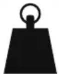
Weight Hazard
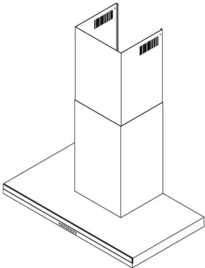
The ventilation hood is heavy. Please ensure adequate care is taken when installing the ventilation hood to prevent personal injury.
The ventilation hood must be installed onto a solid wall, stud, beam or truss.
Weight of the products are 33 lb (15 kg) HC24 / 35 lb (16 kg) HC30 / 37 lb (17 kg) HC36.
WARNING!

Electric Shock Hazard
Always disconnect the appliance from the mains power supply before carrying out any maintenance or repairs.
Installation work and electrical wiring must be done by qualified person(s) in accordance with all applicable codes and standards, including fire-rated construction.
Failure to do so can result in death, electric shock, fire or injury to persons.
IMPORTANT SAFETY INSTRUCTIONS
READ THE ENTIRE SET OF INSTRUCTIONS BEFORE INSTALLING OR USING THIS APPLIANCE. Manuals can also be found on our website www.fisherpaykel.com.
- CAUTION: For general ventilating use only. Do not use to exhaust hazardous or explosive materials and vapors.
-
WARNING! To reduce the risk of fire, electric shock, or injury to persons, observe the following:
-
Use this unit only in the manner intended by the manufacturer. If you have questions, contact the manufacturer. For residential use only.
- Before servicing or cleaning unit, switch power off at service panel and lock the service disconnecting means to prevent power from being switched on accidentally. When the service disconnecting means cannot be locked, securely fasten a prominent warning device, such as a tag, to the service panel.
- Installation work and electrical wiring must be done by qualified person(s) in accordance with all applicable codes and standards, including fire-rated construction.
-
Sufficient air is needed for proper combustion and exhausting of gases through the flue (chimney) of fuel burning equipment to prevent back drafting. Follow the heating equipment manufacturer's guideline and safety standards such as those published by the National Fire Protection Association (NFPA), and the American Society for Heating, Refrigeration and Air Conditioning Engineers (ASHRAE), and the local code authorities.
-
When cutting or drilling into wall or ceiling, do not damage electrical wiring and other hidden utilities.
- Ducted fans must always be vented to the outdoors.
- This unit must be grounded.
- CAUTION: To reduce risk of fire and to properly exhaust air, be sure to duct air outside - Do not vent exhaust air into spaces within walls or ceilings or into attics, crawl spaces, or garages.
- WARNING: To reduce the risk of fire, use only metal ductwork.
- WARNING: To reduce the risk of fire or electric shock, do not use this fan with any solid-state speed control device.
- WARNING: To reduce the risk of a range top grease fire:
- Never leave surface units unattended at high settings. Boilovers cause smoking and greasy spillovers that may ignite. Heat oils slowly on low or medium settings.
- Always turn hood ON when cooking at high heat or when flambéing food (ie Crepes Suzette, Cherries Jubilee, Peppercorn Beef Flambé)
- Clean ventilating fans frequently. Grease should not be allowed to accumulate on fan or filter.
- Use proper pan size. Always use cookware appropriate for the size of the surface element.
- WARNING: To reduce the risk of injury to persons in the event of a range top grease fire, observe the following*:
- SMOTHER FLAMES with a close-fitting lid, cookie sheet, or metal tray, then turn off the burner. BE CAREFUL TO PREVENT BURNS. If the flames do not go out immediately, EVACUATE AND CALL THE FIRE DEPARTMENT.
- NEVER PICK UP A FLAMING PAN - You may be burned.
- DO NOT USE WATER, including wet dishcloths or towels - a violent steam explosion will result.
- Use an extinguisher ONLY if:
- You know you have a Class ABC extinguisher, and you already know how to operate it.
- The fire is small and contained in the area where it started.
- The fire department is being called.
- You can fight the fire with your back to an exit.
- WARNING: Unplug or disconnect the appliance from the power supply before servicing or cleaning.
READ AND SAVE THESE INSTRUCTIONS
INSTALLATION INSTRUCTIONS
Contents of packaging
natural_image
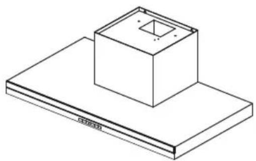
Isometric line drawing of a rectangular box mounted on a flat base, with no text or symbols present.Ventilation hood (1)
text_image
TRANSLATIONAL SOCIETY HISTORY THE NEW JOURNAL OF THE INTERNATIONAL SOCIETY AFTER FROESS & PAPERSInstallation instructions User guide manual (1)
natural_image
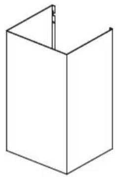
Simple line drawing of a 3D rectangular box with a vertical slot on top (no text or symbols)Chimney (1)
natural_image
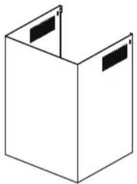
Simple line drawing of a 3D box with two side panels, no text or symbols present.Upper chimney (1)
natural_image
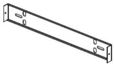
Isometric line drawing of a rectangular metal bracket with mounting holes (no text or symbols)Upper chimney bracket (1)
natural_image
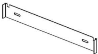
Simple line drawing of a metal bracket with two notches (no text or symbols)Chimney bracket (1)
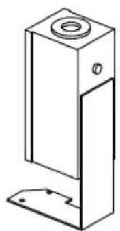
natural_image
Technical line drawing of a mechanical component with a flanged top and base (no text or symbols)Power connection box (1)
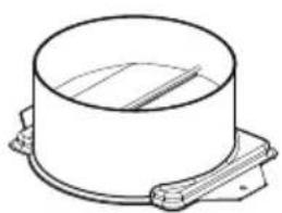
natural_image
Technical line drawing of a cylindrical component with mounting base (no text or symbols)6" (152 mm) diameter Ducting adapter with back draft damper (1)
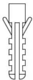
1^3/16 (30 mm)
Expansion plug
(10)
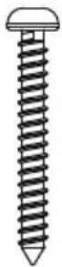
1^3/16 (30 mm)
Self tapping screw
(10)
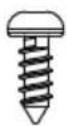
3/8'' (10 mm)
Self tapping screw
(4)
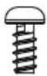
3 / 8 (10 mm)
Screw
(2)
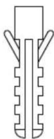
1^3/4 (44 mm)
Drywall expansion plug
(8)
INSTALLATION INSTRUCTIONS
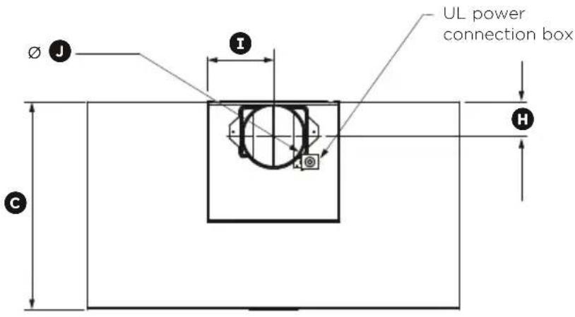
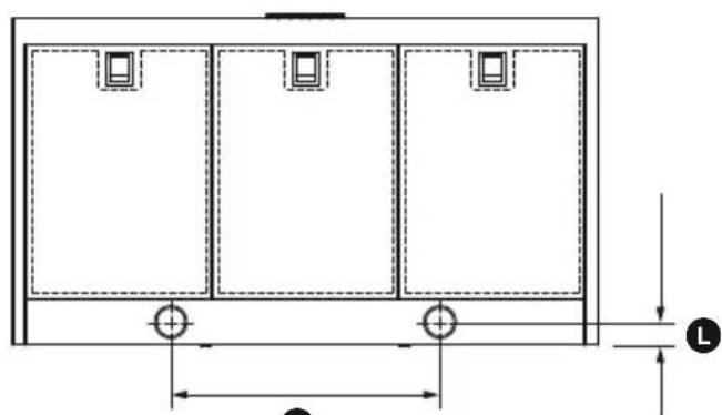
Product dimensions
text_image
UL power connection box Ø J I H C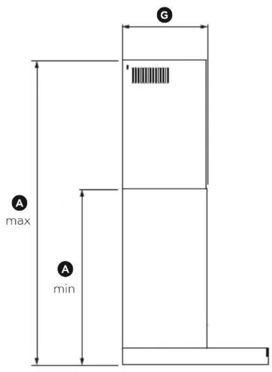
text_image
G A max A min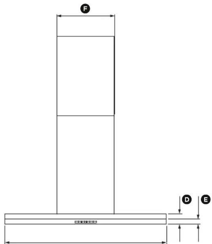
text_image
F D EB
natural_image
Pure architectural or mechanical diagram showing three rectangular panels with mounting holes and dimension lines (no text or symbols)K
Please read the entire instructions before installing the ventilation hood.
HC24DTXB2 HC30DTXB2 HC36DTXB2
| PRODUCT DIMENSIONS inches (mm) inches (mm) inches (mm) | ||||
| A | Min overall height of product 2334" | (603) 2334" (603) | 2334" (603) | |
| A | Max overall height of product 41116" | (1043) 41116" (1043) | 41116" (1043) | |
| B | Overall width of product 23916" (598) | 2934" (755) | 3538" (898) | |
| C | Overall depth of product 19116" (500) | 19116" (500) | 19116" (500) | |
| D | Height of product 2916" (65) | 2916" (65) | ||
| E | Height of stainless steel face panel | 1716" (36) | 1716" (36) | 1716" (36) |
| F | Width of chimney | 1258" (320) | 1258" (320) | 1258" (320) |
| G | Depth of chimney | 11716" (290) | 11716" (290) | 11716" (290) |
| H | Distance from center of ducting outlet to back of product | 338" (85) | 338" (85) | 338" (85) |
| I | Distance from center of ducting outlet to side of chimney | 6516" (160) | 6516" (160) | 6516" (160) |
| J | Diameter of ducting outlet | 6" (152) | 6" (152) | 6" (152) |
| K | Distance between center of lights | 958" (244) | 958" (244) | 958" (244) |
| L | Distance between center of lights and back of product | 138" (35) | 138" (35) | 138" (35) |
IMPORTANT!
Actual product dimensions may vary by ±116 " (2 mm).
INSTALLATION INSTRUCTIONS
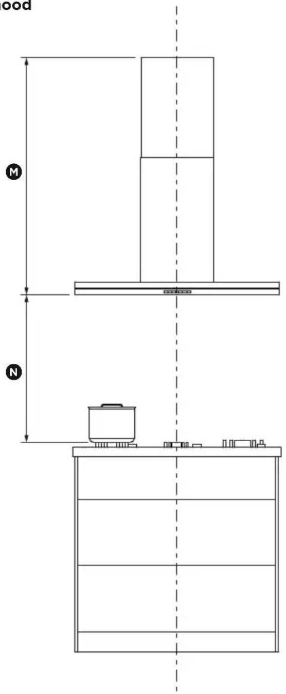
Height of ventilation hood
text_image
ood M N| INSTALLATION DIMENSIONS inches (mm) | |
| M Installation heightDuctedRecirculation | min. 24^1116 ” (627) - max. 43^1116 ” (1034)min. 26^7/8 ” (682) - max. 43^1116 ” (1034) |
| N Height top of cooking surface to base of product | min. 26 ” (660) - max. recommended 36 ” (915) |
This ventilation hood must be installed no lower than the minimum height indicated in the table above. Minimum installation height may be greater if required by the cooktop manufacturer or safety and warning section of this user guide. Installation at the minimum height will improve the efficiency of capturing cooking odors, grease and smoke. Installation at the maximum height improves user ergonomics by offering increased head room.
WARNING!
To reduce the risk of fire, use only metal ductwork. Do not use flexible plastic ducting
CAUTION!
To reduce risk of fire and to properly exhaust air, be sure to duct air outside – do not vent exhaust air into spaces within walls or ceilings or into attics, crawl spaces, or garages.
Venting options
Attention should be given to ensure that any applicable regulations concerning the discharge of exhaust air are fulfilled.
The ventilation hood can be installed to operate with the exhaust air ducted externally from the kitchen, or installed to operate with the exhaust air recirculating within the kitchen.
Ducted
For ducted installation it is recommended that 6" (152 mm) diameter, rigid or semi-rigid ducting is used. This will require a 6516 " (160 mm) (min) round hole in the ceiling or wall. Care should be taken to position the hole correctly.
For optimal efficiency use the shortest and straightest duct route possible and use rigid or semi-rigid ducting for reduced noise and increased airflow. Flexible metal ducting should only be used as a last resort (ie in difficult installations) and if used ensure that it is straight and smooth and extended as much as possible.
Recirculating
To enable the product to operate with the air recirculating, please purchase a recirculation diverter and carbon filters or recirculation kit (refer to the ‘Parts and accessories’ section). This recirculation diverter is required to channel the air out the side vents at the top of the chimney and the carbon filters are required to remove odors.
Note: a ducting hole is not required in the wall or ceiling if the ventilation hood is installed to operate with exhaust air recirculating.
WARNING!
• This product is heavy and requires two persons for installation.
- Installation work and electrical wiring must be done by qualified person(s) in accordance with all applicable codes and standards.
IMPORTANT!
Wear gloves to protect against sharp edges.
The manufacturer is not liable for any damage caused by not following these instructions.
Installation
① Preparing for installation:
Before installing your ventilation hood:
- Please read the instructions carefully.
- Unpack the ventilation hood.
- Ensure the voltage (V) and the frequency (Hz) indicated on the serial plate match the voltage and frequency of the installation site.
- Check that the area behind the installation surface to be drilled is clear of any electrical cables or pipes etc
- The ventilation hood surfaces can be damaged during installation if grazed or knocked by tools. Please take care to protect the surfaces during installation.
- Protect the cooktop surface with cardboard, or the like, to prevent damage occurring whilst the ventilation hood is being installed above.
- Temporarily mark the height of the bottom of the ventilation hood and the center of the cooktop on the wall according to the information given in the ‘Installation instructions – Height of ventilation hood’ section.
- The wall used for mounting the ventilation hood should have sufficient strength and a flat surface.
② Attach chimney brackets and ventilation hood mounting screws to the wall
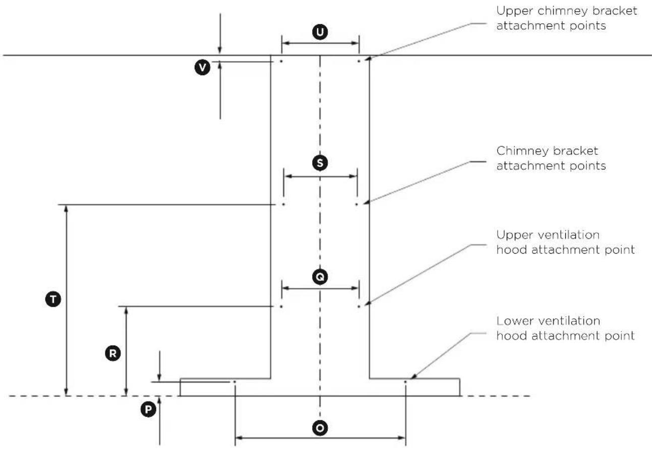
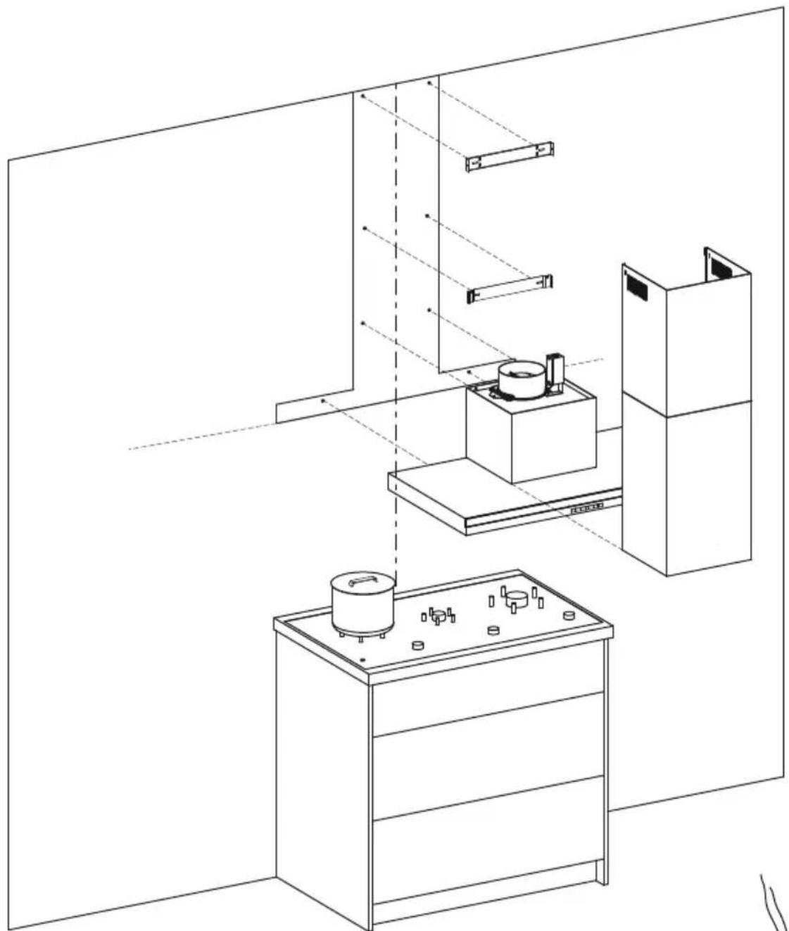
- Attach the chimney bracket and upper chimney bracket (if using the upper chimney) in the locations shown in Fig.2 (refer to page 13) and Fig.3 (refer to page 14). Use the 1^3/16 ” (30 mm) screws (and expansion plugs if attaching to masonry).
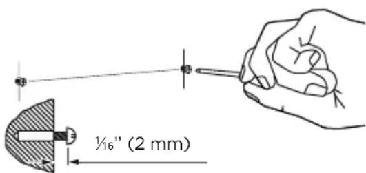
- Attach the upper ventilation hood mounting screws in the locations shown in Fig.2 (refer to page 13) and Fig.3 (refer to page 14). Using the 1^3/16 (30 mm) screws (and expansion plugs if attaching to masonry). Ensure that there is a 116 (2 mm) gap between the screw head and the wall (Fig.1).
text_image
½" (2 mm)Fig.1
text_image
Upper chimney bracket attachment points V U S Chimney bracket attachment points Upper ventilation hood attachment point Q Lower ventilation hood attachment point T R P OFig.2
| PRODUCT DIMENSIONS | inches (mm) | |
| ◎ | Lower ventilation hood attachment point width 20” (508) | |
| ◎ | Lower ventilation hood attachment point height 1^1116 ” (43) | |
| ◎ | Upper ventilation hood attachment point width 978 ” (250) | |
| ◎ | Upper ventilation hood attachment point height 11516 ” (288) | |
| ◎ | Chimney bracket attachment point width 914 ” (235) | |
| ◎ | Chimney bracket attachment point height 2214 ” (566) | |
| ◎ | Upper chimney bracket attachment point width 978 ” (250) | |
| ◎ | Upper chimney bracket attachment point height 1” (25) | |
natural_image
Line drawing of a laboratory setup with equipment and storage (no text or symbols)Fig.3
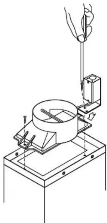
③ Attach ducting adapter and power connection box to the ventilation hood
- Place the ducting adapter onto the ventilation hood and screw it in place using 38 " (10 mm) screws.
- Place the power connection box onto the ventilation hood and screw it in place using 38'' (10 mm) screws.
- Follow wiring instructions described in the 'Electrical connection' section page 16.
natural_image
Technical line drawing of a mechanical testing setup with a tool and base (no text or symbols)④ Wall mounting
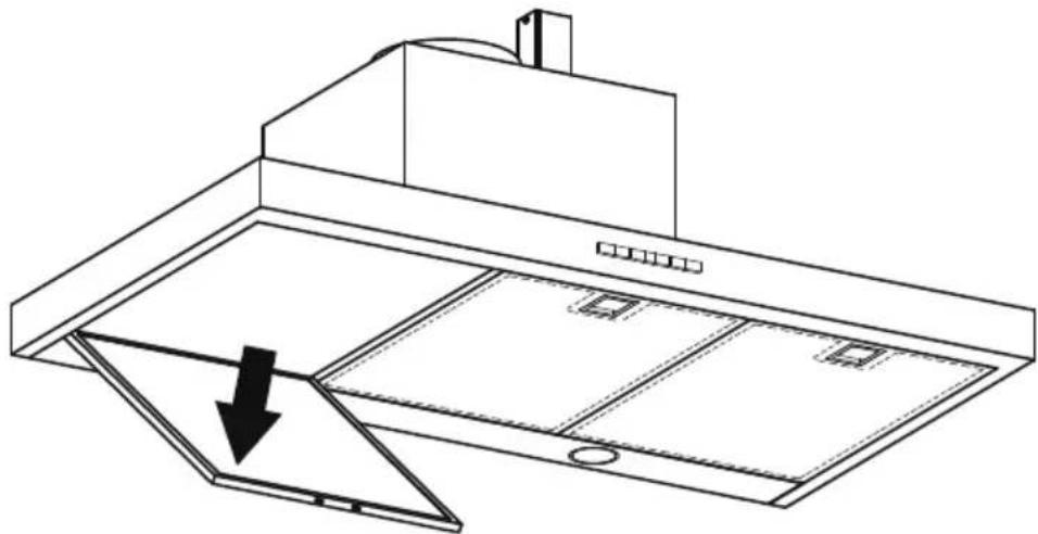
- Remove the filters - pull the relative catch and tilt the filter downwards until it disengages from the supports.
natural_image
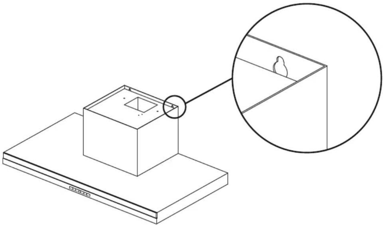
Line drawing of a kitchen chimney with an open door and outlet, showing internal compartments and a downward arrow indicating airflow (no text or symbols)- Hang the ventilation hood off the upper ventilation hood mounting screws with 116 ” (2 mm) gap. Hang off the keyhole attachment points on the back of the ventilation hood then tighten the screws.
natural_image
Isometric line drawing of a small box mounted on a base, with an inset showing a close-up of its top panel (no text or symbols present)- Attach the lower ventilation hood mounting screws to fix the ventilation hood to the wall.
- Refit the filters.
WARNING!
Electrical wiring must be done by qualified person(s) in accordance with all applicable codes and standards and the unit must be grounded.
⑤ Electrical connection
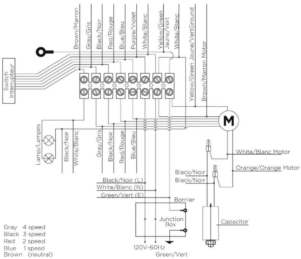
- Run three wires, two for the power supply and one for the ground wire, from the power connection box on the ventilation hood to a power connection point near the installation.
- Open the power connection box on the ventilation hood and secure the power conductor with a cULus listed strain relief (not included).
- Connect the power conductors to the conductors for the ventilation hood, black to black and white to white.
- Connect the grounding wire (green or bare) to the ground conductor (green) of the ventilation hood power connection box.
- Secure all the connections with cULus listed wire nuts.
- Replace the power connection box cover.
text_image
Switch Interrupteur Brown/Marron Gray/Gris Black/Noir Red/Rouge Blue/Bleu Purple/Violet White/Blanc Yellow/Green Jaune/Vert White/Blanc Yellow/Green Jaune/VertGround Brown/Marron Motor M Lamp/Lampes Black/Noir White/Blanc Gray/Gris Black/Noir Red/Rouge Blue/Bleu Black/Noir (L) White/Blanc (N) Green/Vert (E) Bonnier Junction Box Capacitor 120V-60Hz Green/Vert Gray 4 speed Black 3 speed Red 2 speed Blue 1 speed Brown (neutral)⑥ Attach the ducting
- Attach ducting to the ducting adapter using aluminum duct tape and vent outside.
⑦ Attach chimney
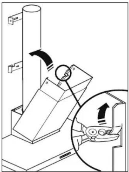
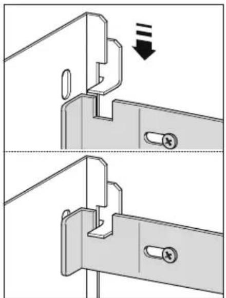
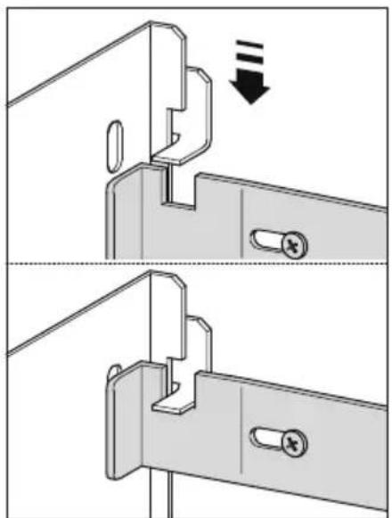
- Bend the tabs on the chimney (A).
- Place chimney around the ventilation hood chassis and hang off the chimney bracket (B).
- Extend the upper chimney and attach to the upper chimney bracket with 116 " (10 mm) screws (C).
natural_image
Technical diagram of a mechanical device with an inset showing a close-up of a component being turned, no text or symbols present.ABC
natural_image
Technical diagram showing two mechanical assembly steps with a downward arrow indicating a process (no text or symbols present)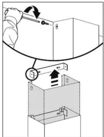
text_image
Diagram illustrating a mechanical assembly or mounting process with labeled components and directional arrows indicating motion.⑧ Remove packaging
- Remove all packaging and protective wrappings.
OPERATING INSTRUCTIONS
Touch control panel
 |  | — |  |  |  |  |
CONTROL PANEL FEATURES
 | Light Turn the lights on or off. | |
 | Power ON/OFF Turn the ventilation hood on or off. The fan automatically turns on to operate at level 1. | |
| - | Reduce fan speed Adjust the fan speed levels from 1 - 4 with 1 being the lowest. | |
 | Fan speed indicator The fan speed level icon illuminates red with the current fan speed. | |
| + | Increase fan speed Adjust the fan speed levels from 1 - 4 with 4 being the highest. | |
 | Max Turn the fan on directly onto maximum fan speed. | |
 | Timer Turn the timer on. The fan speed light blinks and the fan will operate for 5 minutes at the current speed and each decreasing speed before turning off (the fan will stop and the light will go out).To cancel the timer press the timer button once. | |
Note: for optimal performance it is recommended that the ventilation hood is turned on before cooking is started.
IMPORTANT!
The ventilation hood may stop working during an electrostatic discharge (eg lightning). Switch off the electricity supply to the ventilation hood and reconnect after one minute.
WARNING!
Unplug or disconnect the appliance from the power supply before servicing or cleaning.
IMPORTANT!
• Never use abrasive or oil based cleaners.
- Wear gloves to protect against sharp edges.
Maintenance
The ventilation hood should be cleaned regularly using a mild, liquid detergent and a clean soft cloth to avoid a build-up of grease occurring. Avoid the use of corrosive chemicals, abrasive cleaning products, hard brushes and steel wool pads. Grease deposits are corrosive which can cause damage to your ventilation hood.
Note: in areas of high humidity or coastal environments, cleaning should be carried out more frequently.
Aluminum filters
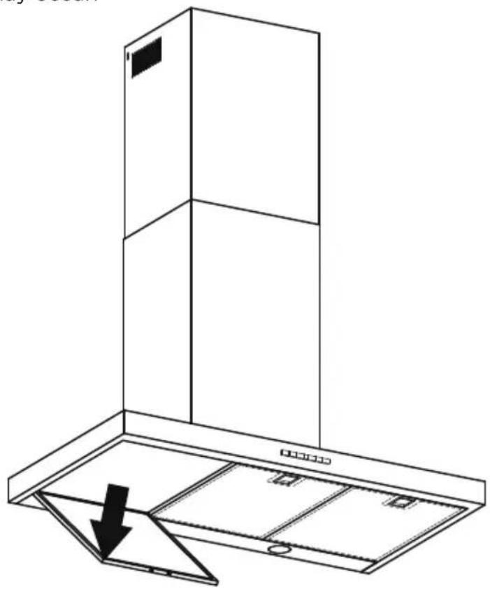
- Depending on use, and at least once a month, the aluminum filters should be removed and cleaned with hot soapy water or in a dishwasher.
- If washed in a dishwasher, the filter should be placed in an upright position to prevent food from falling on them.
• After rinsing and drying, refit the filters.
Note: some discoloration of the frames may occur.
Removing the aluminum filters:
① Pull the relative catch, tilting the filter downwards until it disengages from the supports.
② Reverse these instructions when refitting the filters.
natural_image
Line drawing of a double door with an open lid and a black arrow indicating downward motion (no text or symbols)WARNING!
When replacing the bulb, let the bulb cool, and assure that power to the ventilation hood has been turned off. Use new bulbs according to that indicated on the ventilation hood nameplate.
Carbon filters - for use in recirculation mode
Active carbon filters are disposable items designed to remove grease and odors from cooking vapors before the air is channeled back into the kitchen. The active carbon filters must be replaced periodically to work properly, at least once every three months, depending on the frequency with which the ventilation hood is used.
Note: fully saturated carbon filters can become a barrier to air movement therefore limiting ventilation hood performance. In the event of fire, grease laden filters could be flammable and therefore regular replacement is recommended.
Replacing the light bulb
Note: replacement bulbs are not covered by warranty.
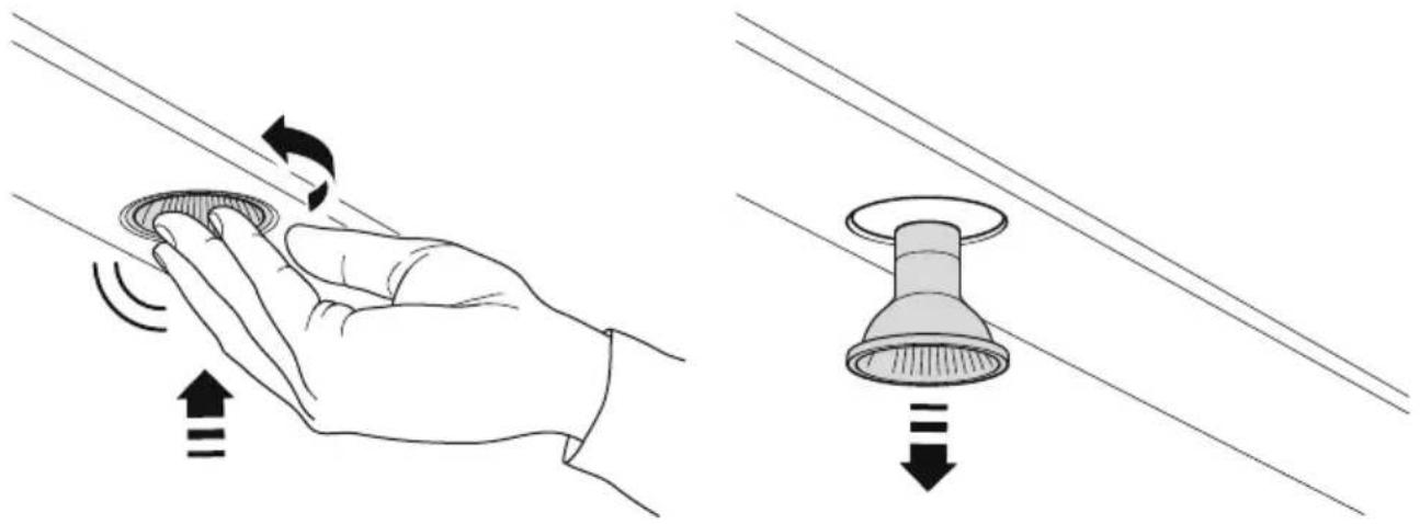
① Remove the aluminum filters.
② Lightly push the light bulb up and rotate anti-clockwise to remove.
③ Replace light bulb with a light bulb no more powerful than that specified.
④ Refit the aluminum filters.
natural_image
Illustration of a hand holding a circular component with directional arrows indicating motion, next to a close-up of a circular component with downward arrow (no text or symbols)| ITEM REFERENCE NUMBER | |
| LED bulb 792579 | |
| Aluminum filter 792558 | |
| Recirculation carbon filter x2 791772 | |
| Recirculation diverter 792580 |
When you purchase any new Fisher & Paykel ventilation hood for personal or consumer use you automatically receive a two year limited warranty covering parts and labor for servicing within the 48 mainland United States, Hawaii, Washington DC and Canada. In Alaska the limited warranty is the same except that you must pay to ship the product to the service shop or the service technician's travel to your home. Products for use in Canada must be purchased through the Canadian distribution channel to ensure regulatory compliance.
If the product is installed in a motor vehicle, boat or similar mobile facility, you receive the same two year limited warranty, but you must bring the vehicle, boat or mobile facility containing the product to the service shop at your expense or pay the service technician's travel to the location of the product.
There is no warranty for commercial purchase or use.
Fisher & Paykel undertakes to:
Repair without cost, with limited exceptions described herein, to the owner either for material or labor any part of the product, the serial number of which appears on the product, which is found to be defective. In Alaska, you must pay to ship the product to the service shop or for the service technician's travel to your home. If the product is installed in a motor vehicle, boat or similar mobile facility, you must bring it to the service shop at your expense or pay for the service technician's travel to the location of the product. If we are unable to repair a defective part of the product after a reasonable number of attempts, at our option we may replace the part or the product, or we may provide you a full refund of the purchase price of the product (not including installation or other charges).
This warranty extends to the original purchaser and any succeeding owner of the product during the term of the warranty for products purchased for ordinary single-family home use.
All service under this limited warranty shall be provided by Fisher & Paykel or its Authorized Service Agent during normal business hours.
How long does this limited warranty last?
Our liability under this limited warranty expires TWO YEARS from the date of purchase of the product by the first consumer.
Our liability under any implied warranties, including the implied warranty of merchantability (an unwritten warranty that the product is fit for ordinary use) expires TWO YEARS (or such longer period as required by applicable law) from the date of purchase of the product by the first consumer. Some States do not allow limitations on how long an implied warranty lasts, so this limit on implied warranties may not apply to you. Fisher & Paykel will honor any warranty required by the law of the particular country or state in which the product is sold.
This limited warranty does not cover:
Ⓐ Service calls that are not related to any defect in the product. The cost of a service call will be charged if the problem is not found to be a defect of the product. For example:
① Correcting faulty installation of the product.
② Instructing you how to use the product.
③ Replacing house fuses, resetting circuit breakers, correcting house wiring or plumbing, or replacing light bulbs.
④ Correcting fault(s) caused by the user.
⑤ Changing the set-up of the product.
⑥ Unauthorized modifications of the product.
⑦ Noise or vibration that is considered normal, for example, fan sounds/noises or user warning beeps.
⑧ Correcting damage caused by pests, for example, rats, cockroaches, etc
⑨ Replacement light bulbs.
B Defects caused by factors other than:
① Normal domestic use; or
② Use in accordance with the product's user guide.
© Defects to the product caused by accident, neglect, misuse, fire, flood or 'act of God'.
D The cost of repairs carried out by non-authorized repairers or the cost of correcting such unauthorized repairs.
E Travel fees and associated charges incurred when the product is installed in a location with limited or restricted access (eg airplane flights, ferry charges, isolated geographic areas).
⑤ Normal recommended maintenance as set out in the product's user guide.
⑥ Filter replacement except in the case of faulty parts or materials within the filter cartridge.
⑧ Damage (including water damage) caused by faulty installation, plumbing or wiring.
This product has been designed for use in a normal domestic (residential) environment. This product is not designed for commercial use (whatsoever). Any commercial use by a customer will terminate this product's limited warranty.
If you have an installation problem contact your dealer or installer. You are responsible for providing adequate electrical, exhausting and other connection facilities.
Fisher & Paykel will not be responsible for consequential or incidental damages (including, without limitation, the cost of repairing or replacing other property damaged if the product is defective or any of your expenses caused if the product is defective). Some States do not allow the exclusion or limitation of incidental or consequential damages, so the above limitation or exclusion may not apply to you.
How to get service
Please read your user guide. If you then have any questions about operating the product, need the name of your local Fisher & Paykel Authorized Service Agent, or believe the product is defective and wish service under this limited warranty, please contact your dealer or call us at:
USA and Canada
TOLL FREE 1.888.9.FNP.USA (1.888.936.7872)
or use the link at: www.fisherpaykel.com/locator/servicer/
You may be required to provide reasonable proof of the date of purchase of the product before the product will be serviced under this limited warranty.
No other warranties
This limited warranty is the complete and exclusive agreement between you and Fisher & Paykel regarding any defect in the product and no other express warranty has been made or will be made on behalf of Fisher & Paykel. None of our employees (or our Authorized Service Agents) are authorized to make any addition or modification to this limited warranty.
Warrantor: Fisher & Paykel Appliances, Inc.
If you need further help concerning this limited warranty, or need to make a claim under this warranty, please call us at the above number, or write to:
Fisher & Paykel Appliances, Inc.
695 Town Center Drive, Suite 180
Costa Mesa
CA 92626
This limited warranty gives you specific legal rights, and you may also have other rights which vary from country to country and from state to state.
Complete and keep for safe reference:
Model
Serial No. ____
Purchase Date ____
Purchaser
Dealer
Suburb ____
Town
Country ____
Introduction
29
natural_image
Isometric line drawing of a three-tiered rectangular structure mounted on a base plate (no text or symbols)MISE EN GARDE!
33 lb (15 kg) (HC24)
35 lb (16 kg) (HC30)
37 lb (17 kg) (HC36)
natural_image
Isometric line drawing of a rectangular box mounted on a flat base, with no text or symbols present.Hotte de ventilation (1)
text_image
TRANSLATIONAL SOCIETY HISTORY THE NEW CHINESE OF THE SOCIATION AFTER-IN-THY'S LONDON THE NEW CHINESE OF THE SOCIATION FROESS & FAMILInatural_image
Simple line drawing of a 3D rectangular box with a vertical slot on top (no text or symbols)Cheminée (1)

natural_image
Simple line drawing of a 3D box with two side panels (no text or symbols)natural_image
Isometric line drawing of a rectangular metal bracket with mounting holes (no text or symbols)natural_image
Simple line drawing of a metal bracket with two notches (no text or symbols)natural_image
Technical line drawing of a mechanical component with a flanged top and base (no text or symbols)natural_image
Technical line drawing of a cylindrical component with mounting base (no text or symbols)text_image
Technical diagram showing three rectangular panels with mounting holes and dimension labels L and KHC24DTXB2 HC30DTXB2 HC36DTXB2
text_image
ventilation M Nnatural_image
Line drawing of a laboratory setup with equipment and storage (no text or symbols)Fig.3
natural_image
Technical line drawing of a mechanical testing setup with a tool and base (no text or symbols)④ Montage au mur
natural_image
Line drawing of a kitchen chimney with an open door and ventilation slots (no text or symbols)natural_image
Isometric line drawing of a small box mounted on a base, with an inset showing a close-up of its top panel (no text or symbols present)natural_image
Technical diagram of a mechanical device with an inset showing a close-up of a component being turned, no text or symbols present.ABC
natural_image
Technical diagram showing two mechanical assembly steps with a downward arrow indicating a process (no text or symbols present)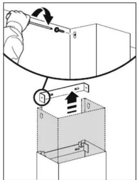
text_image
Diagram illustrating a mechanical assembly or mounting process with labeled components and directional arrows indicating motion.⑧ Retirez l'emballage
natural_image
Line drawing of a double door with an open lid and a downward arrow indicating a drop or change (no text or symbols)MISE EN GARDE!
natural_image
Illustration showing a hand pressing down on a cable with directional arrows indicating motion (no text or symbols)Fisher & Paykel Appliances, Inc.
695 Town Center Drive, Suite 180
Costa Mesa
CA 92626
© Fisher & Paykel Appliances 2017. All rights reserved.
The product specifications in this booklet apply to the specific products and models described at the date of issue. Under our policy of continuous product improvement, these specifications may change at any time. You should therefore check with your Dealer to ensure this booklet correctly describes the product currently available.