HCB36-6N - Range hood Fisher & Paykel - Free user manual and instructions
Find the device manual for free HCB36-6N Fisher & Paykel in PDF.


| Product type | Range hood |
| Model | HCB36-6N |
| Brand | Fisher & Paykel |
| Width | 911 mm (35 7/8 in) |
| Depth | 636 mm (25 1/16 in) |
| Height | 457 mm (18 in) |
| Electrical supply | 120 V AC, 60 Hz, 20 A |
| Number of speeds | 4 (LOW, MED, HIGH, MAX) |
| Lighting | 2 halogen GU10 50 W bulbs (HIGH/LOW dimming) |
| Duct type | Rigid metal, Ø 8 in (203 mm) standard, optional Ø 10 in (254 mm) |
| Installation | Wall-mounted or under cabinet, external exhaust only |
| Recommended installation height | 762 to 1,067 mm (30 to 42 in) above cooking surface |
| Filters | Dishwasher-safe metal grease filters |
| Filter cleaning | Every month minimum |
| Material | Stainless steel |
| Options | Infrared lamp panel, 10 in duct transition, cover panels |
| Warranty | See the provided service and warranty manual |
Frequently Asked Questions - HCB36-6N Fisher & Paykel
User questions about HCB36-6N Fisher & Paykel
0 question about this device. Answer the ones you know or ask your own.
Ask a new question about this device
Download the instructions for your Range hood in PDF format for free! Find your manual HCB36-6N - Fisher & Paykel and take your electronic device back in hand. On this page are published all the documents necessary for the use of your device. HCB36-6N by Fisher & Paykel.
USER MANUAL HCB36-6N Fisher & Paykel
HC36 (Shell) & HC48 (Shell) models
HOTTE PROFESSIONNELLE
Safety and warnings 4
Product information 6
Installation preparation 8
Installation instructions 16
Operating instructions 24
Cleaning and maintenance 25
Maintenance
27
Parts and accessories 28
Service and warranty 29
IMPORTANT!
SAVE THESE INSTRUCTIONS
The models shown in this user guide may not be available in all markets and are subject to change at any time. For current details about model and specification availability in your country, please go to our website fisherpaykel.com or contact your local Fisher & Paykel dealer.
Registration
Register your product with us so we can provide you with the best service possible.
To register your product visit our website: fisherpaykel.com
Welcome to the family of Fisher & Paykel appliances. Our team has spent thousands of hours designing, engineering and testing it to make sure you get the perfect product for your home. For more information visit our website or for further support, contact our customer care team.
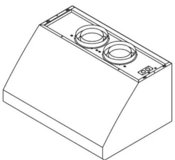
natural_image
Isometric line drawing of a rectangular electronic enclosure with two circular cutouts on top (no text or symbols)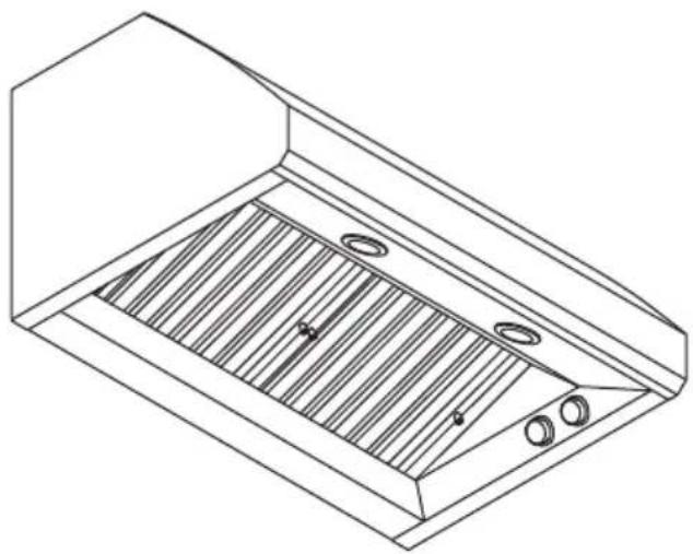
natural_image
Line drawing of a 3D kitchen or oven structure with slatted ventilation duct and circular fixtures (no text or symbols)WARNING!
Weight Hazard
The appliance is heavy. Please ensure adequate care is taken when installing the appliance to prevent personal injury. Weight of the products are:
HCB30 = 66lb (30kg)
HCB36 = 75lb (34kg)
HCB48 = 99lb (45kg)
HC36 = 68lb (31kg)
HC48 = 84lb (38kg)
WARNING!

Electric Shock Hazard
Always disconnect the appliance from the mains power supply before carrying out any maintenance or repairs.
Installation work and electrical wiring must be done by qualified person(s) in accordance with all applicable codes and standards, including fire-rated construction.
Failure to do so can result in death, electric shock, fire or injury to persons.
IMPORTANT SAFETY INSTRUCTIONS
READ THE ENTIRE SET OF INSTRUCTIONS BEFORE INSTALLING OR USING THIS APPLIANCE.
CAUTION: For general ventilating use only. Do not use to exhaust hazardous or explosive materials and vapors.
WARNING: To reduce the risk of fire, electric shock, or injury to persons, observe the following:
- Use this unit only in the manner intended by the manufacturer. If you have questions, contact the manufacturer. For residential use only.
- Before servicing or cleaning unit, switch power off at service panel and lock the service disconnecting means to prevent power from being switched on accidentally. When the service disconnecting means cannot be locked, securely fasten a prominent warning device, such as a tag, to the service panel.
- Installation work and electrical wiring must be done by qualified person(s) in accordance with all applicable codes and standards, including fire-rated construction.
-
Sufficient air is needed for proper combustion and exhausting of gases through the flue (chimney) of fuel burning equipment to prevent back drafting. Follow the heating equipment manufacturer's guideline and safety standards such as those published by the National Fire Protection Association (NFPA), and the American Society for Heating, Refrigeration and Air Conditioning Engineers (ASHRAE), and the local code authorities.
-
When cutting or drilling into wall or ceiling, do not damage electrical wiring and other hidden utilities.
- Ducted fans must always be vented to the outdoors.
- This unit must be grounded.
CAUTION: To reduce the risk of fire and to properly exhaust air, be sure to duct air outside. Do not vent exhaust air into spaces within walls or ceilings or into attics, crawl spaces, or garages.
WARNING: To reduce the risk of fire, use only metal ductwork.
WARNING: To reduce the risk of fire or electric shock, do not use this fan with any solid-state speed control device.
WARNING: To reduce the risk of a range top grease fire:
- Never leave surface units unattended at high settings. Boilovers cause smoking and greasy spillovers that may ignite.
- Heat oils slowly on low or medium settings.
- Always turn hood ON when cooking at high heat or when flambéing food (ie Crepes Suzette, Cherries Jubilee, Peppercorn Beef Flambé)
- Clean ventilating fans frequently. Grease should not be allowed to accumulate on fan or filter.
- Use proper pan size. Always use cookware appropriate for the size of the surface element.
WARNING: To reduce the risk of injury to persons in the event of a range top grease fire, observe the following*:
- Smother flames with a close-fitting lid, cookie sheet, or metal tray, then turn off the burner. Be careful to prevent burns. If the flames do not go out immediately, evacuate and call the fire department.
- Never pick up a flaming pan — you may be burned.
- Do not use water, including wet dishcloths or towels—a violent steam explosion will result.
- Use an extinguisher only if:
- You know you have a Class ABC extinguisher, and you already know how to operate it.
- The fire is small and contained in the area where it started.
- The fire department is being called.
- You can fight the fire with your back to an exit.
WARNING: All wall and floor openings where the range hood is installed must be sealed.
READ AND SAVE THESE INSTRUCTIONS
General information
Please read this manual carefully, and keep it after installation as it will help answer questions that may arise as you use your new Fisher & Paykel range hood.
Keep all packing material (box, pallet, straps) until the unit has been inspected. Inspect the product to check there is no shipping damage. If any damage is detected contact the dealer or retailer you bought the product from to report the damage. Fisher & Paykel is not responsible for shipping damage.
WARNING!
For residential use only.
Parts included with your range hood:
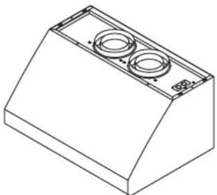
natural_image
Isometric line drawing of a rectangular electronic component with two circular cutouts on top (no text or symbols)Range hood with light bulbs and 8" (203mm) duct connection rings installed (1)

User guide (1)
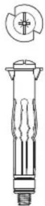
Wall plug (2)
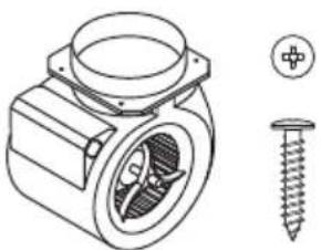
natural_image
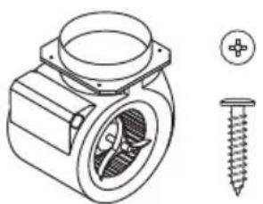
Technical line drawing of a mechanical component with screw and nut (no text or symbols)Internal blower, including 3/4" (19mm) screws (4)
- HCB30-6 (1)
• HCB36-6 (1)
• HCB36-12 (2)
• HCB48-12 (2)
HC36/48 (0)
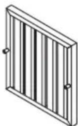
natural_image
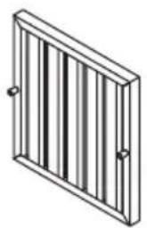
Isometric line drawing of a rectangular fence with vertical slats and two small protrusions (no text or symbols)Filters
- HCB30 (2)
• HCB36/HC36 (2)
• HCB48/HC48 (3)
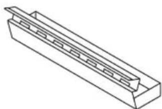
natural_image
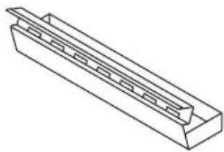
Isometric line drawing of a mechanical component with grooves and a central slot (no text or symbols)Grease trays
- HCB30 (2)
• HCB36/HC36 (2)
• HCB48/HC48 (3)
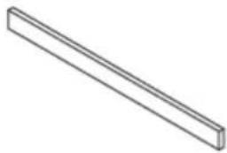
natural_image
Simple 3D line drawing of a rectangular prism (no text or symbols)Wooden bracket (length depending on model) found mounted to the back of the range hood. Used as part of the installation DO NOT THROW AWAY

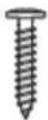
3/4" (19mm) Self-tapping screw (8)
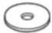
3/4" (19mm) Flat washer (2)


3" (76mm) Self-tapping screw (4)
Other required materials and tools:
- Metal ducting.
• Aluminum tape (DO NOT use duct tape).
• 3/4" (19mm) cULus approved wiring conduit and connectors.
• 3/4" (19mm) cULus approved strain relief.
• cULus listed wire nuts.
• Back draft damper(s) if desired.
Product dimensions
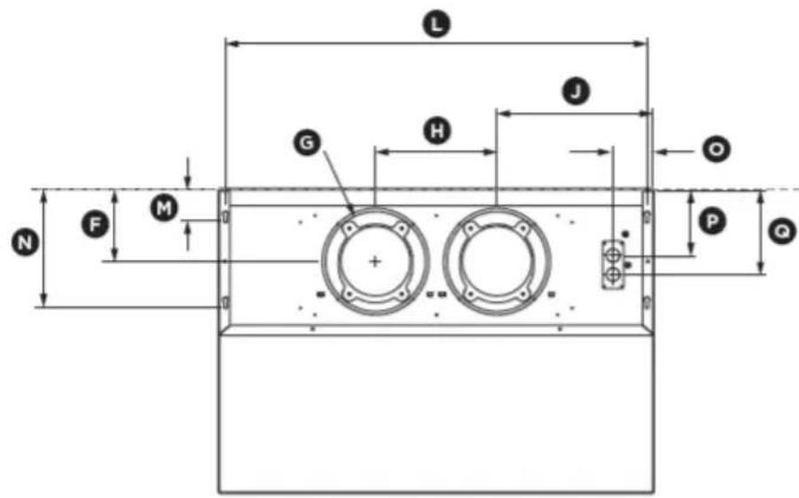

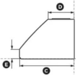

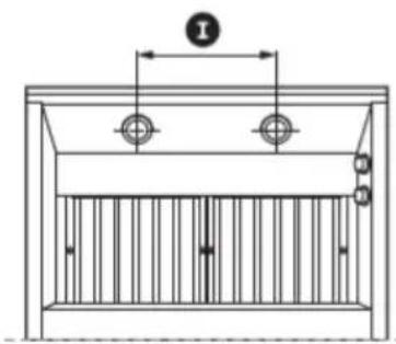
natural_image
Technical line drawing of a cabinet or enclosure with vertical slats and mounting holes (no text or symbols)HCB30-6 HCB36-6 HCB36-12
HCB48-12
HC36
HC48
| PRODUCT DIMENSIONS inches (mm) inches (mm) inches (mm) inches (mm) | ||||
| A Overall height of product 18" (457) 18" (457) 18" (457) 18" (457) | ||||
| B Overall width of product 29 7/8" (759) 35 7/8" (911) 35 7/8" (911) 47 7/8" (1216) | ||||
| C Overall depth of product 25 1/16" (636) 25 1/16" (636) 25 1/16" (636) | ||||
| D Depth of top face of product 12" (305) 12" (305) 12" (305) | 12" (305) | |||
| E Height of front face | 4 5/16" (110) | 4 5/16" (110) | 4 5/16" (110) | 4 5/16" (110) |
| F Distance from center of ducting outlet to back of product | 5 7/8" (150) | 5 7/8" (150) | 5 7/8" (150) | 5 7/8" (150) |
| G Diameter of ducting outlet | 8 3/16" (208) | 8 3/16" (208) | 8 3/16" (208) | 8 3/16" (208) |
| H Distance between center of blowers | N/A | N/A | 10 1/16" (255) | 10 1/16" (255) |
| I Distance between center of lights | 12" (305) | 13 3/4" (350) | 13 3/4" (350) | 12" (305) |
| J Distance between center of blower to side of range hood | 14 15/16" (380) | 17 15/16" (456) | 12 15/16" (328) | 18 7/8" (480) |
| K Distance between wall mounting slots | 17 5/8" (448) | 17 5/8" (448) | 17 5/8" (448) | 17 5/8" (448) |
| L Distance between under cabinet mounting slots | 28 7/8" (734) | 34 7/8" (886) | 34 7/8" (886) | 46 7/8" (1191) |
| M Distance from wall to rear under cabinet mounting slots | 2 5/8" (66) | 2 5/8" (66) | 2 5/8" (66) | 2 5/8" (66) |
| N Distance from wall to front under cabinet mounting slots | 9 11/16" (246) | 9 11/16" (246) | 9 11/16" (246) | 9 11/16" (246) |
| O Dimension from side of range hood to junction box knockout | 3 7/8" (98) | 3 5/16" (84) | 3 5/16" (84) | 6 1/16" (154) |
| P Dimension from back to rear junction box knockout | 5 7/16" (138) | 5 7/16" (138) | 5 7/16" (138) | 5 7/16" (138) |
| Q Dimension from back to front junction box knockout | 7" (178) | 7" (178) | 7" (178) | 7" (178) |
| R Height from top of range hood to recess on back | 2 1/2" (63) | 2 1/2" (63) | 2 1/2" (63) | 2 1/2" (63) |
| S Height from bottom of range hood to top of recess on back | 15 1/2" (394) | 15 1/2" (394) | 15 1/2" (394) | 15 1/2" (394) |
| T Distance between wall plug mounting holes. | 17 5/8" (448) | 17 5/8" (448) | 17 5/8" (448) | 17 5/8" (448) |
IMPORTANT!
- Actual product dimensions may vary by ± 1/16" (2mm).
- Please read the entire instructions before installing the range hood.
INSTALLATION PREPARATION
Product dimensions
Differences if 10" duct transition is added to HCB36-12, HCB48-12, HC36, HC48

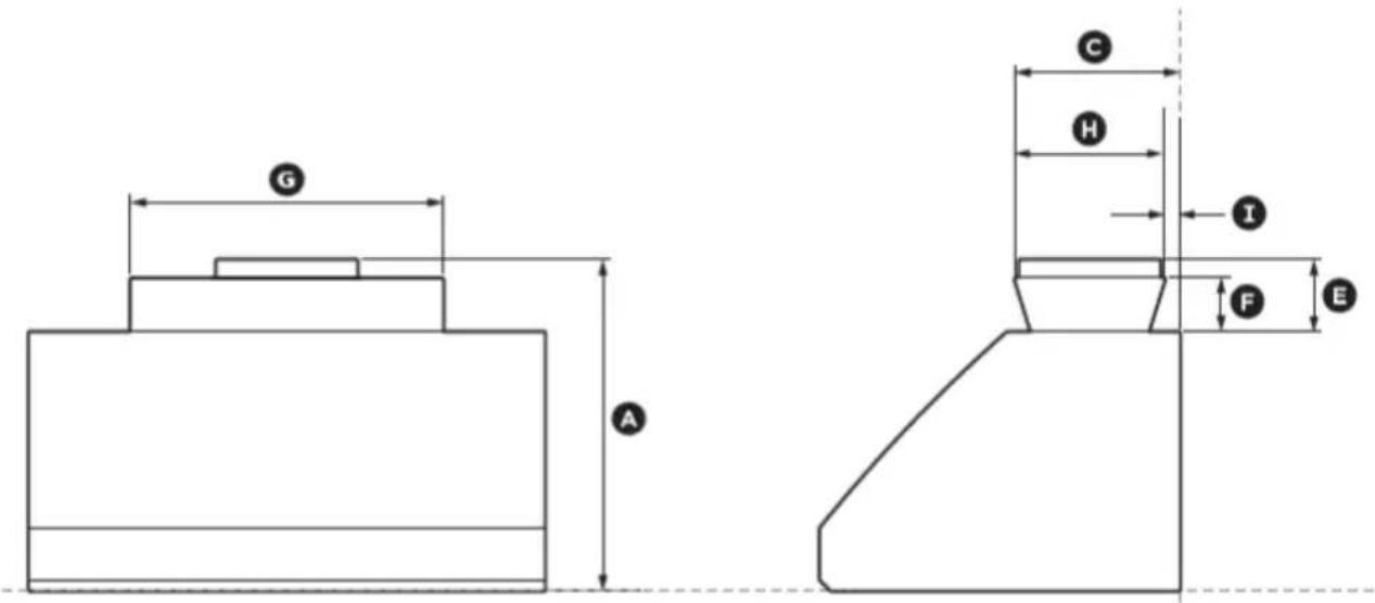
| PRODUCT DIMENSIONS inches (mm) | |
| A | Overall height of product with ducting transition added 23” (585) |
| B | Overall width of ducting transition 22 13/16” (580) |
| C | Overall depth of ducting transition to wall 11” (280) |
| D | Outlet diameter 10” (254) |
| E | Height of transition outlet pipe above range hood 5” (128) |
| F | Height of transition body above range hood 3 3/4” (95) |
| G | Width of transition body 21 3/4” (552) |
| H | Depth of transition body 10 1/16” (256) |
| I | Distance from back edge of cooktop to transition body 1 1/16” (26) |
| J | Distance from centre of outlet to wall 6 1/4” (159) |
IMPORTANT!
• Actual product dimensions may vary by ± 1/16" (2mm).
- Please read the entire instructions before installing the range hood.
INSTALLATION PREPARATION
Range hood width
- The range hood width is recommended to be no less than the width of the cooktop.
- A wider range hood can be used to increase the capture area if space is not restricted.
• The range hood should ideally be centered above the cooktop for proper performance.
Determine installation location
WARNING!
• To reduce the risk of fire, use only metal ductwork.
• Do not use flexible ducting.
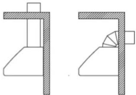
This range hood can be installed using a wall mounting system or be suspended under cabinetry. Ducting can be configured for both vertical and horizontal discharge. The ducting can terminate either through the roof or wall. To vent through the wall a 90° elbow is needed.
natural_image
Pure mechanical cross-section diagrams without any text, numbers, or symbolsHeight of the range hood
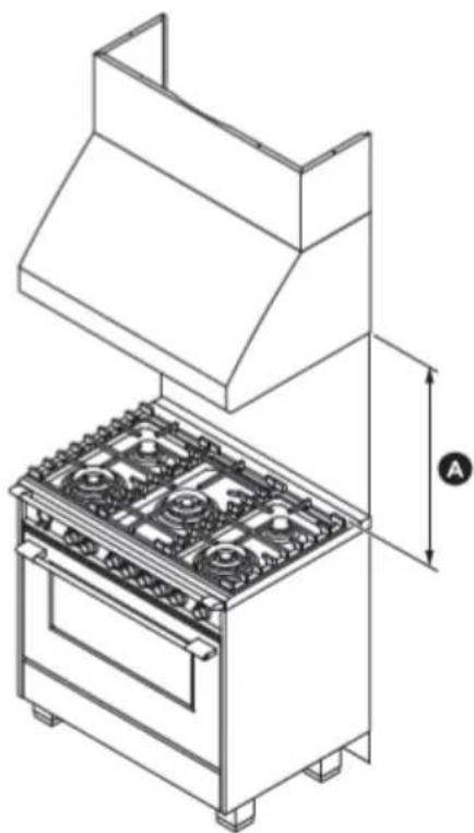
The installation height ranges from a minimum height of 30" (762mm) to a maximum recommended height of 42" (1067mm). Consult the cooktop installation and user guide for details of the required installation height of the range hood.
This range hood must be installed no lower than the minimum height indicated in the table below. Minimum installation height may be greater if required by the cooktop manufacturer. Installation at the minimum height will improve the efficiency of capturing cooking odors, grease and smoke. Installation at the maximum recommended height improves user ergonomics by offering increased head room.
IMPORTANT!
• Always switch your range hood on when you are cooking.
- Using a powerful gas cooktop or multiple gas burners operating at the same time can cause the range hood surfaces to become hot, this effect can be reduced by:
- Using the maximum speed setting to enable hot air to be extracted quickly.
- Installing the range hood at the maximum recommended height. Consult the cooktop installation and user guide for details on the installation height of the range hood.
natural_image
Technical line drawing of a kitchen furnace with four fans and a side panel, showing internal components (no text or symbols)| INSTALLATION DIMENSIONS | inches (mm) | |
| A | Top of cooking surface to base of the range hood | Minimum 30" (762mm)Maximum recommended 42" (1067mm) |
Calculating the installation height
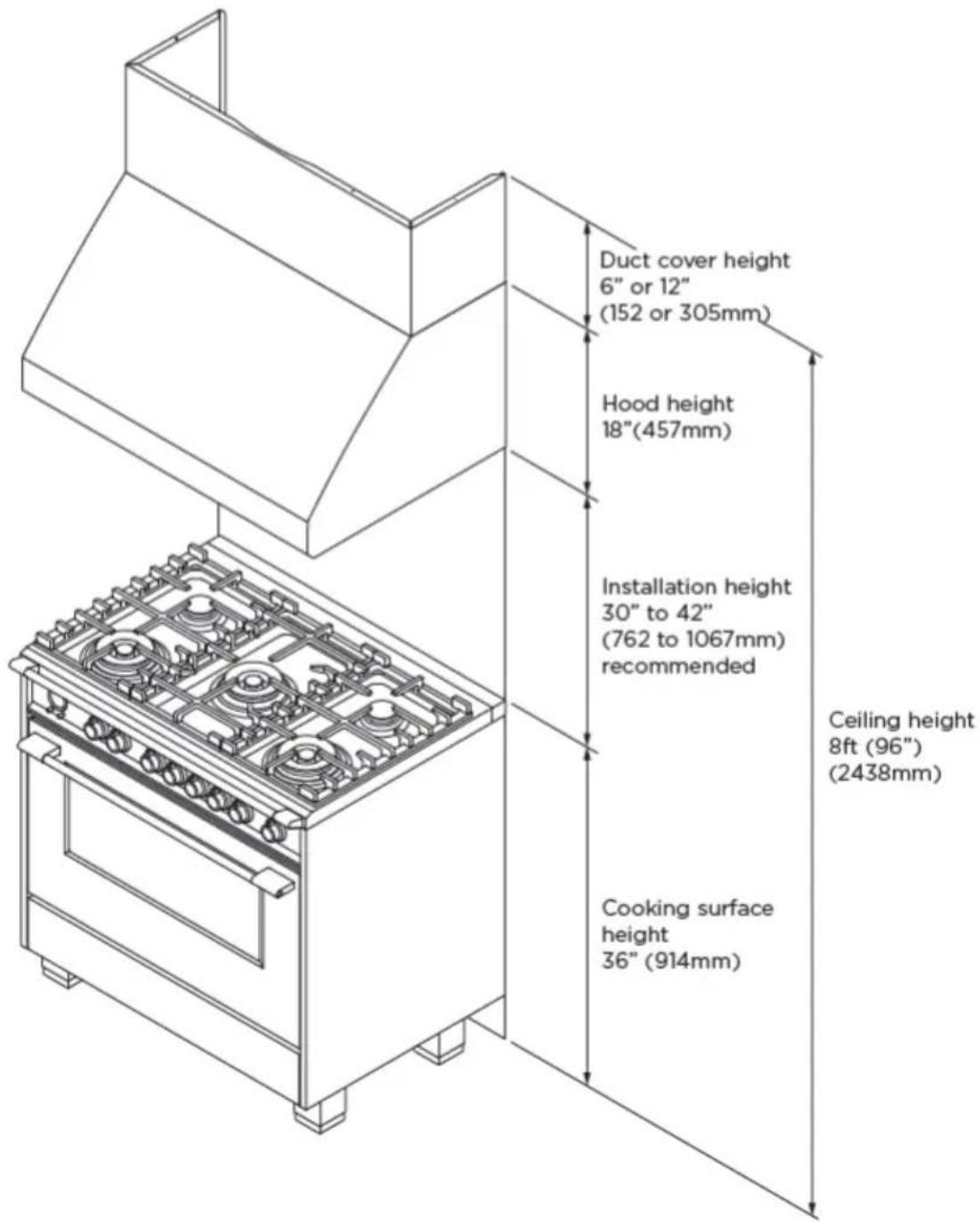
Installation height for a standard 96" (2438mm) high kitchen ceiling is shown below. Use the following formula to calculate installation height:
$$ A = W - (X + Y + Z) $$
Where:
A = Installation height
W= Ceiling height
X = Cooktop surface height
Y = Range hood height
Z = Duct cover height (if desired)
Example: (A) Installation height = 96" - (36" + 18" + 12") = 30"
Example: (A) Installation height = 2438mm - (914mm + 457mm + 305mm) = 762mm
Optional extras
Duct covers
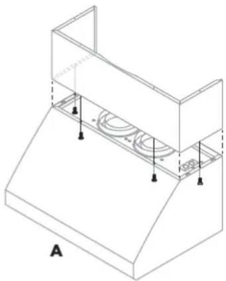
Duct covers may be used to fill the space between the range hood and the ceiling in wall mount installations. These covers are available in 6" (152mm) and 12" (305mm) sizes and may be ordered separately, see 'Parts and accessories'. Refer to 'Installation instructions' for calculation of installation height to determine which duct cover(s) may be required.
Duct cover installation
① Place the duct cover on the range hood.
② From inside of range hood, insert the 5/16" (8mm) T20 (TORX) head machine screws through the 4 holes in the duct cover (refer to A).
natural_image
Isometric line drawing of a technical enclosure or duct with mounting base and internal circular components (no text or symbols)Note: Multiple duct covers can be used if additional height is required. Duct covers are available in 6" (152mm) and 12" (305mm) heights. Screw the duct covers together before placing them onto the range hood and completing step ②.
Duct transition
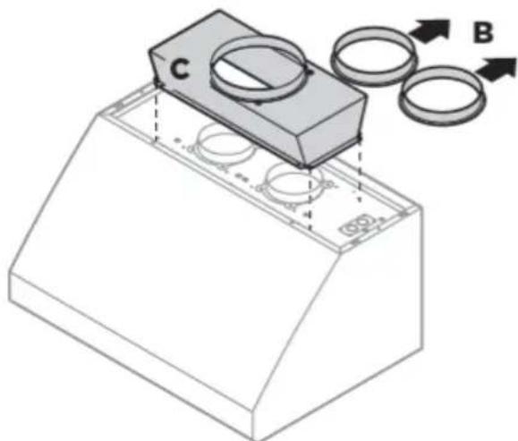
- The range hood is supplied with individual duct connection rings that connect to 8" (208mm) ducting, (refer to B).
- An optional transition may be ordered separately, please refer to 'Parts and accessories' for details. This can be mounted to the top of the range hood to provide a single 10" (254mm) outlet.
- For wall mounting installation the transition should be installed before the range hood is mounted.
- For cabinet mounting installation the transition should be mounted after installing the range hood.
Duct transition assembly
① Remove the individual 8" (203mm) duct connection rings (refer to B).
② Place the transition piece over the range hood exhaust, secure from the inside of the range hood with 5/16" (8mm) T20 (TORX) head machine screw provided with the transition (refer to C).
③ Seal the connection between the transition and range hood with aluminum tape (refer to D).
natural_image
3D diagram of a mechanical component with labeled parts (A, B, C) and directional arrows indicating movement or force (no text or symbols beyond labels)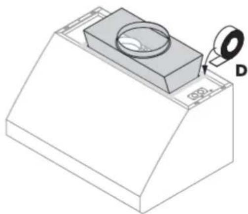
natural_image
3D technical illustration of a mechanical component with a circular feature and a labeled part D (no text or symbols present)Infra-red heat lamp and panel kit
If an optional infra-red heat lamp kit was purchased for installation with the range hood, assemble the kit to the range hood prior to installation. See instructions supplied with the kit for assembly to your range hood.
WARNING!
To avoid any electrical shock the installation of the infra-red heat lamp and panel kit should be done by a qualified electrician and before starting the installation of the range hood.
Electrical requirements
WARNING!
- Installation and electrical wiring must be done by qualified person(s) in accordance with all applicable codes and standards.
• This unit must be grounded/earthed.
• This range hood must be connected with copper wire only. - A 120 volt, 60Hz AC-only electrical supply is required on a dedicated 20A branch circuit. A time-delay fuse or circuit breaker is recommended.
- Wire sizes must conform to the requirements of the National Electrical Code, ANSI/NFPA 70-latest edition, and all local codes and ordinances.
- Wire size and connections must conform to the rating of this appliance.
- This appliance should be connected directly to the fuse disconnect (or circuit breaker) through flexible, armored or non-metallic sheathed copper cable. Allow some slack in the cable so the appliance can be moved if servicing is required.
- A cULus listed strain relief or 3/4" (19mm) conduit connector must be provided at each end of the power supply cable (at the appliance and at the junction box).
WARNING!
To reduce the risk of fire or electric shock, do not use this fan with any solid-state speed control device.
Venting requirements
CAUTION!
To reduce risk of fire and to properly exhaust air, be sure to duct air outside—Do not vent exhaust air into spaces within walls or ceilings or into attics, crawl spaces, or garages.
- The range hood can be installed to operate with the exhaust air ducted externally from the kitchen.
- Use the shortest and straightest duct route possible, for optimal efficiency. Elbows and transitions increase noise and reduce air flow efficiency.
-
For best results:
-
In ducted installations with internal blowers use 8" (203mm) round ducting.
- For inline blowers use 10" (254mm) round ducting.
Note: This range hood cannot be used in conjunction with a recirculation unit.
Make-up air (not included)
Attention should be given to ensure that any applicable regulations concerning the discharge of exhaust air are fulfilled.
- Local building codes may require the use of make-up air systems when using ducted ventilation systems greater than specified cubic feet per minute (CFM) of air movement. The specified CFM varies from locale to locale.
- It is the responsibility of the owner and the installer to determine if additional requirements and/or standards apply to specific installations.
Compatible blowers
This range hood may only be used in connection with these internal or inline blowers:
• Internal blowers come with the range hood (for HCB30/36/48 range hood models).
• Inline blowers can be purchased separately (for HC36/48 range hood models).
This range hood may only be used with a Fisher & Paykel approved inline blower. To minimize noise in the kitchen, these blowers are mounted along the duct line anywhere between the kitchen and the exterior wall.
CAUTION!
To reduce the risk of fire and electric shock, install this range hood only with remote blower models rated maximum 7.6A or integral blowers supplied with the range hood.
WARNING!
• This appliance is heavy and requires two persons for unpacking and installation.
• Installation work and electrical wiring must be done by qualified person(s) in accordance with all applicable codes and standards.
- Failure to install the screws or fixing device in accordance with these instructions may result in electrical hazards.
- When cutting or drilling into wall or ceiling, do not damage electrical wiring and other hidden utilities.
IMPORTANT!
- Wear gloves to protect against sharp edges.
- The manufacturer is not liable for any damage caused by not following these instructions.
Before you start installation
- Ensure you have read the 'Installation preparation' section of this guide.
- Read the install instructions carefully.
• Unpack the range hood. - Ensure the voltage (V) and the frequency (Hz) indicated on the serial plate match the voltage and frequency of the installation site.
- Check that the area above and behind the installation surface is clear of any electrical cables or pipes and there is proper clearance for the ducting.
- The range hood surfaces can be damaged during installation if grazed or knocked by tools.
- Protect the cooktop to prevent damage occurring whilst the range hood is being installed above.
- Remove protective wrappings that will not be accessible after installation.
- The wall or cabinet used for mounting the range hood should have sufficient strength and a flat surface.
natural_image
Technical line drawing of a kitchen appliance with visible cabinetry and ventilation system (no text or labels)Wall mounting installation
After the range hood installation height has been determined:
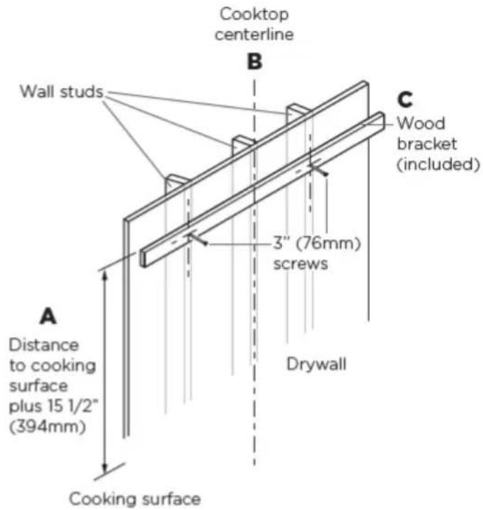
① Draw a horizontal line at a distance above the cooktop equal to the desired range hood installation height plus 15 1/2" (394mm) (refer to A).
- This line is the mounting location of the top of the wooden bracket supplied with the range hood.
② Find the centerline of the cooktop. Draw a vertical line along this centerline up to the horizontal line drawn in step ① (refer to B).
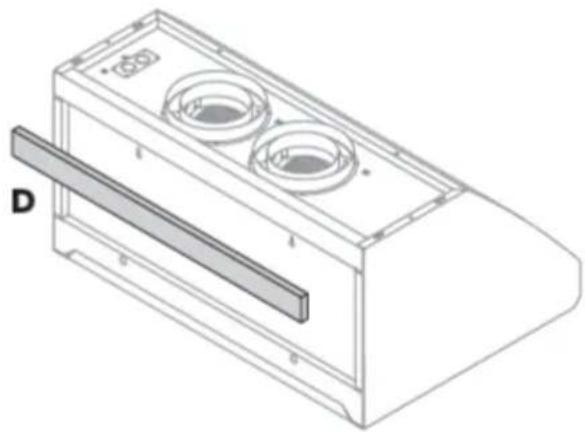
③ The range hood is mounted to the wall using a wooden bracket supplied with the range hood (refer to D). Remove the wooden bracket from the rear of the range hood. Mark the centerline of the bracket.
④ Find studs behind the drywall by using a stud finder. Locate one stud on either side of the cooktop centerline to use for mounting the wooden bracket (refer to C).
⑤ Align the top of the wood bracket along the horizontal line drawn in step ①. Align the centerlines of the bracket and cooktop (refer to A).
⑥ Drill a 3" (76mm) deep 1/8" (3mm) hole through the wooden bracket, drywall and into the stud.
⑦ Use the 3" (76mm) screws to attach the bracket to the wall (refer to A). For support of longer range hoods, use three or four studs and screws as available. Countersink the heads to prevent interference with the range hood.
⑧ On the wood bracket, mark the distance between wall mounting slots (K in the 'Product dimensions' section) to hang the range hood (refer to E).
⑨ Drill two 1/8" (3mm) holes through the wooden bracket and drywall (these do not need to go into the studs) (refer to E).
⑩ Screw two 3/4" (19mm) screws into the wood bracket, leaving 1/4" (6mm) of the screw exposed for hanging the range hood (refer to E).
natural_image
Technical line drawing of a rectangular electronic device with two circular cutouts and a shaded base (no text or symbols)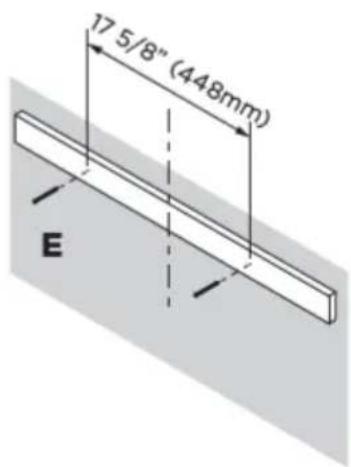
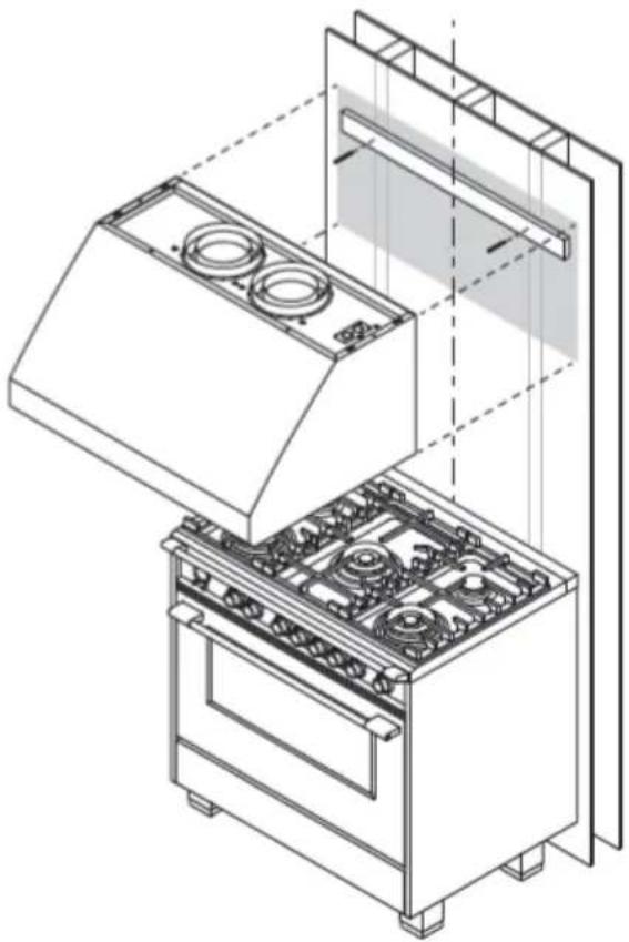
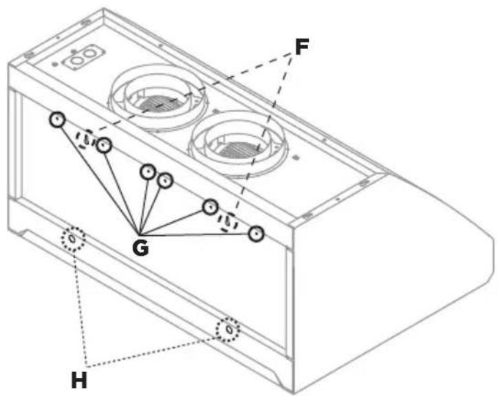
⑪ Using two people lift and hang the range hood using the keyhole slots (refer to F). Make sure the wood bracket fits into the recess on the back of the range hood.
⑫ Level the range hood and tighten the 3/4" (19mm) screws in the keyhole slots.
⑬ From inside the range hood, drive four or six 3/4" (19mm) screws (depending on model) through the holes indicated (refer to G) into the wooden bracket.
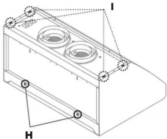
⑭ Drill a 3/8" (9.5mm) hole through the center of the holes indicated in H into the wall. Insert two wall plugs into the drilled holes.
Tighten the range hood to the wall plugs by installing the 3/4" (19mm) washers onto the screws supplied with the wall plug, then tighten.
⑮ Attach the duct to the 10" (254mm) transition or the 8" (203mm) duct rings and screws (not supplied) and seal with aluminum tape.
Note: For wall installations the optional duct transition should be fitted to the range hood prior to wall mounting. Please refer to 'Duct transition assembly' for details.
Cabinet mounting installation
The range hood can be installed under a cabinet by supporting the range hood from the top. For cabinet mounting installation the transition should be mounted after installing the range hood, see ‘Duct transition assembly’ and ‘Product dimensions’ sections. If the transition is used allowance needs to be made in the cabinetry back wall for easier ducting attachment and sealing.
WARNING!
The cabinet must be of sufficient strength and structurally joined to the wall studs to support the weight of this range hood.
IMPORTANT!
It is recommended that the cabinet has a door or service panel that can be easily opened to access the power connection box.
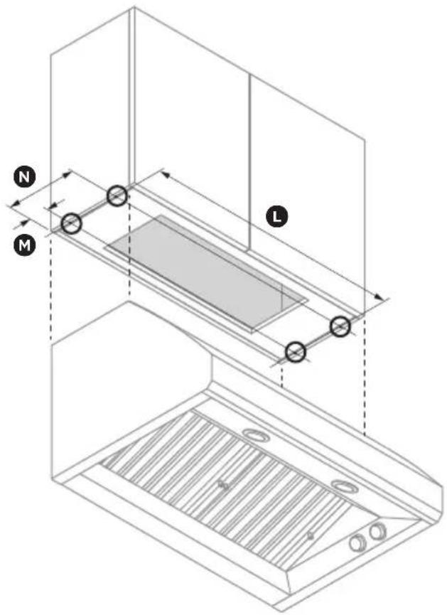
① To determine the location for the four screws that will secure the range hood to the cabinet, refer to 'Product dimensions' for measurements of L, M and N.
② Draw a line to mark distance L along the underside of your cabinet.
③ At either end of L, draw two lines, one at distance M from the wall, the other one at distance N from the wall. This will give you the 4 positions for the screw holes.
Note: Allow space for the power conduit, and ducting attachment in the cabinetry base.
④ In the base of the cabinet, drill 1/8" (3mm) holes as marked.
⑤ Screw four 3/4" (19mm) screws leaving 1/4" (6mm) of the screw exposed to hang the range hood on.
⑥ Using two people lift and hang the range hood from the screws through keyslots provided on range hood top (refer to Ⅰ). Tighten the four screws.
⑦ Drill a 3/8" (9.5mm) hole through the center of the holes indicated in H into the wall. Insert two wall plug into the drilled holes. Tighten the range hood to the wall plugs by installing the 3/4" (19mm) washers onto the screws supplied with the wall plug, then tightening.
⑧ If using a optional duct transition, attach the 10" (254mm) transition now, see 'Duct transition assembly' section for details.
⑨ Attach the duct to the 10" (254mm) transition or 8" (203mm) duct rings with screws (not supplied) and seal with aluminum tape.
natural_image
Technical line drawing of a rectangular electronic device with three circular components and labeled points (I, G, H), no readable text or symbols present.Internal blower installation (HCB30/36/48 range hood models only)
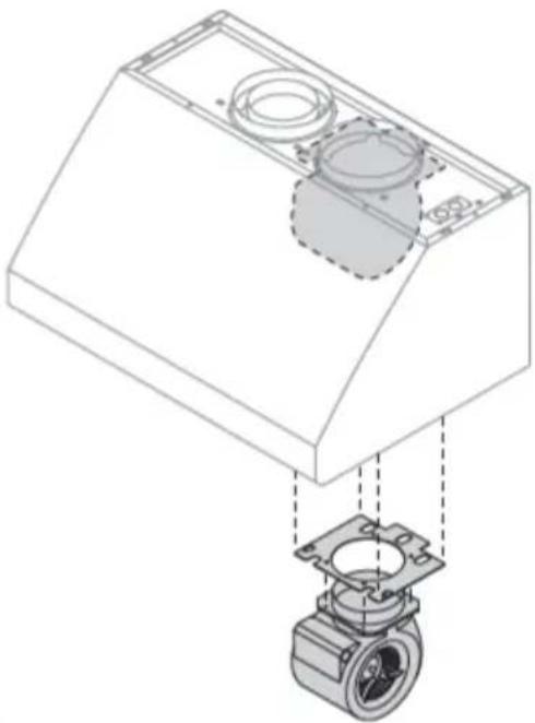
The internal blower can be mounted as shown below.
① From the inside of the range hood, loosen the 1/2" (12.7mm) screws securing the blower plate to the range hood.
② Slide the blower plate towards you and lower it out of the range hood.
③ Attach the blower plate to the blower using the 3/4" (19mm) screws provided.
④ Lift the blower into the range hood, fit the rear of the blower plate onto the mounting bracket.
⑤ Lift the front of blower upwards until the screws enter the keyhole slots on the blower plate.
⑥ Push the blower away from you (to the rear of the range hood) and tighten the 1/2" (12.7mm) screws to secure the blower to the range hood.
natural_image
Technical line drawing of a mechanical assembly with a housing and mounting base (no text or symbols)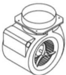
natural_image
Technical line drawing of a mechanical component with no visible text or symbolsBlower without plate attached

Blower with plate attached
Inline blower connection (HC36 and HC48 range hood models only)
For inline blower installation see the instructions supplied with the inline blower unit.
Electrical connection
WARNING!
- Electrical wiring must be done by qualified person(s) in accordance with all applicable codes and standards and the unit must be grounded.
- Turn off electricity at the service panel before wiring the unit.
- A 120 volt, 60Hz AC-only electrical supply is required on a dedicated 20A branch circuit. A time-delay fuse or circuit breaker is recommended.
- Use only with range hood cord-connection kits that have been investigated and found acceptable for use with this model range hood.
Range hood internal blower electrical connection (HCB30/36/48 models only)
① Connect the plug present inside the range hood to the internal blower.
② Remove the junction box cover as shown below.

③ Remove knockouts as required and install a cULus listed 3/4" (19mm) wiring conduit and conduit connector or strain relief in the junction box.
④ Run three wires for the power supply through the 3/4" (19mm) strain relief or conduit from the power supply to junction box. Tighten the strain relief.
⑤ Connect the power supply wires to the range hood wires in the following order using cULus listed wire nuts:
- black to black wire
- white to white wire
- green/yellow wire to green wire.
⑥ Close the range hood junction box cover.
Complete the installation
① Remove all protective wrapping from range hood.
② Install the filters and grease trays as described in the 'Cleaning and maintenance' section.
③ Turn the power on at the control panel.
④ Check the operation of the range hood as described in the 'Operating instructions' section.
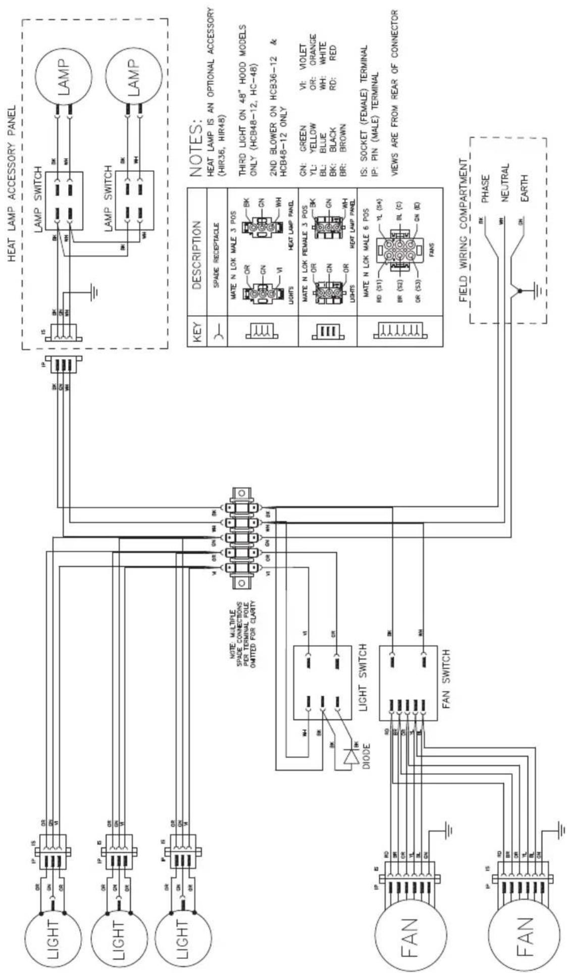
Wiring diagram
flowchart
graph TD
    subgraph Light
        direction TB
        A["Light"] --> B["OR"]
        B --> C["IP"]
        C --> D["IS"]
        D --> E["OR"]
        E --> F["VI"]
        G["Light"] --> H["OR"]
        H --> I["IP"]
        I --> J["IS"]
        J --> K["OR"]
        K --> L["VI"]
        M["Light"] --> N["OR"]
        N --> O["IP"]
        O --> P["IS"]
        P --> Q["OR"]
        Q --> R["VI"]
        S["Light"] --> T["OR"]
        T --> U["IP"]
        U --> V["IS"]
        V --> W["OR"]
        X["Light"] --> Y["OR"]
        Y --> Z["IP"]
        Z --> AA["IS"]
    end

    subgraph LightSwitch
        direction TB
        AB["DIODE"] --> AC["LIGHT SWITCH"]
        AD["FAN"] --> AE["FAN SWITCH"]
    end

    subgraph FieldWiringCompartment
        direction TB
        AF["FAN"] --> AG["IP"]
        AG --> AH["IS"]
        AH --> AI["RD"]
        AI --> AJ["OR"]
        AJ --> AK["IN"]
        AL["NOTE: MULTIPLE SPADE CONNECTIONS PER TERMINAL POLE OMITTED FOR CLARITY"]
    end

    subgraph LAMP
        direction TB
        AM["LAMP SWITCH"] --> AN["LAMP"]
        AN --> AO["LAMP"]
        AP["LAMP"] --> AQ["LAMP"]
    end

    note right of AB
        Legend:
        Key
    end

    note right of AC
        Legend:
    Legend:
    Legend:
    Legend:
    Legend:
    Legend:
    Legend:
    Legend:
    Legend:
    Legend:
    Legend:
    Legend:
    Legend:
    Legend:
    Legend:
    Legend:
    Legend:
    Legend:
    Legend:
    Legend:
    Legend:
    Legend:
    Legend:
    Legend:
    Legend:
    Legend:

    note right of AB
        Legend:
        Legend:
        Legend:
        Legend:
        Legend:
        Legend:
        Legend:
        Legend:
        Legend:
        Legend:
        Legend:
        Legend:
        Legend:
        Legend:
        Legend:
        Legend:
        Legend:
        Legend:
        Legend:
        Legend:
        Legend:
        Legend:
        Legend:
        Legend:
        Legend:
        Legend:

    note right of AB
        Legend:
        Legend:
        Legend:
        Legend:
        Legend:
        Legend:
        Legend:
        Legend:
        Legend:
        Legend:
        Legend:

    note right of AB
        Legend:
        Legend:
        Legend:
        Legend:
        Legend:
        Legend:
        Legend:

    note right of AB
        Legend:
        Legend:
        Legend:
        Legend:
        Legend:

    note right of AB
        Legend:
        Legend:
        Legend:
        Legend:

    note right of AB
        Legend:
        Legend:
        Legend:

    note right of AB
        Legend:
        Legend:
        Legend:

    note right of AB
        Legend:
        Legend:

    note right of AB
        Legend:
        Legend:

    note right of AB
        Legend:
        Legend:

    note right of AB
        Legend:
        Legend:

    note right of AB
        Legend:
        Legend:

    note right of AB
        Legend:
        Legend:

    note right of AB
        Legend:
        Legend:

    note right of AB
        Symbol:
      Blue = GREEN, OR = YELLOW, BL = BLUE, BK = BLACK, BR = BROWN, IS = SOCKET (FEMALE) TERMINAL, IP = PIN (MALE) TERMINAL, VIEWS ARE FROM REAR OF CONNECTOR

    Note right of AB
        Note right of AB
            Spade Receptacle
            MATE N LOK MALE 3 POS
            OR
            GN
            VI
            LIGHTS
            HEAT LAMP PANEL
            MATE N LOK FEMALE 3 POS
            OR
            GN
            IR
            LIGHTS
            HEAT LAMP PANEL
            MATE N LOK MALE 6 POS
            RD (S11)
            BR (S22)
            OR (S33)
            FANS

    Note right of AB
        Feature labels on left and right are extracted from the diagram. The diagram is labeled 'HEAT LAMP ACCESSORY PANEL'.
Control panel
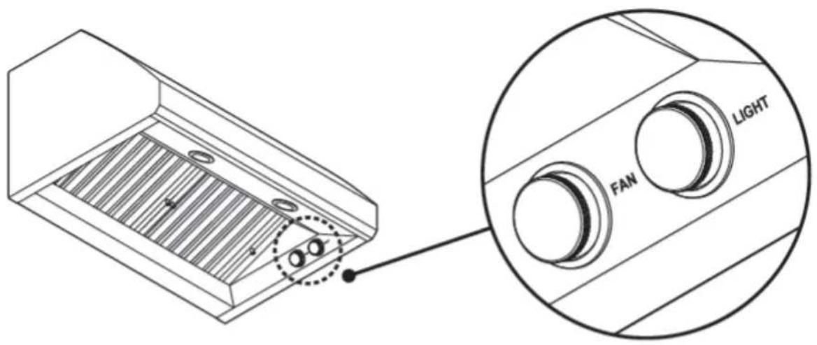
| CONTROL PANEL FEATURES | |
| Fan speed control | Turn the range hood fan on or off.Turn to LOW, MED, HIGH or MAX as needed.Always use the MAX setting when grilling. |
| Light control | Turn the range hood light on or off.Adjust the light levels from LOW to HIGH. |
General operating information
• The range hood should be turned on for a few minutes before cooking:
- To establish air currents up-ward through the range hood.
- Help remove hot air from your kitchen and keep the range hood surface cool. When heat, smoke, moisture, grease and cooking odors are produced, they will be carried outside instead of drifting into other rooms.
WARNING!
- Before servicing or cleaning your range hood, switch the power off at the control panel and disconnect the power to prevent the range hood from being switched on accidentally.
- Allow the appliance to cool after the power has been turned off before servicing.
IMPORTANT!
• Never use abrasive or oil based cleaners.
- Wear gloves to protect against sharp edges.
Cleaning
General cleaning
To avoid the build-up of grease and damage to your range hood:
- Clean your range hood regularly using a mild, liquid detergent and a clean soft cloth. - Do not use corrosive chemicals, abrasive cleaning products, citrus based cleaning products, hard brushes and steel wool pads.
Note: In areas of high humidity or coastal environments, cleaning should be carried out more frequently.
Filters and grease trays
Filters and grease tray should be cleaned at least once a month:
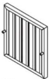
- Filters and grease trays should be removed and cleaned with hot soapy water or in a dishwasher.
• If washed in a dishwasher, the filter and grease tray should be placed in an upright position.
• After cleaning and drying, refit the filters and grease trays.
The filters must always be in place when the range hood is in use, as they prevent damage to the inside of the range hood. Grease trays must be in place before installing the filters.
To remove the filters:
① Grasp the filter knobs, push up and pull towards you to allow the back of the filter to come free of the grease trays (refer to A).
② Lower the back of the filter down to disengage the filter from the front of the range hood (refer to B).

natural_image
Isometric technical diagram of a ventilation duct with slats and ventilation slots, labeled A (no text or symbols on the diagram itself)
natural_image
Technical diagram of a heat exchanger or cooling unit with labeled component B (no text or symbols beyond label)To remove the grease trays:
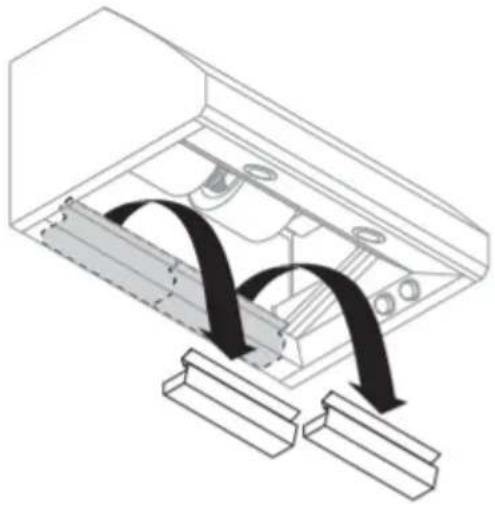
① Grasp the grease tray and push away from you. This will disengage the grease tray from the range hood.
② Lift the grease tray up and out of the range hood track.
natural_image
Diagram of a computer monitor with two USB drive slots and internal components (no text or labels)To replace the grease trays:
① Keep the back end of the grease tray tilted down as you insert it, lower the back of the grease tray into the range hood track.
② Ensure the bottom of the grease tray is seated flat in the range hood track.
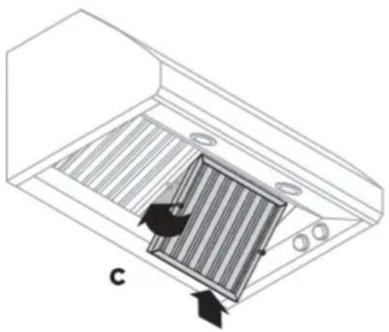
To replace the filters:
① Hold the filter by the knobs.
② Insert the front of the filter into the front track of the range hood and slide toward you (refer to C).
③ Lift the back of the filter up and lower it into the grease tray.
④ Slide the filter back until it firmly seats into place (refer to D).
natural_image
Technical diagram of a heat exchanger or cooling unit with internal cooling fins and heat flow arrows (no text or symbols)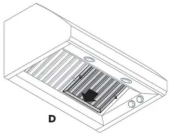
natural_image
Isometric technical diagram of a rectangular device with internal grating and mounting holes (no text or symbols)Light bulb replacement
IMPORTANT!
- Wear gloves to protect against sharp edges.
• DO NOT TOUCH the light bulb when in use. They may be hot enough to cause injury.
Note: Replacement bulbs are not covered by warranty.
To replace the light bulb:
- Turn off the range hood and allow the light bulb to cool.
- Disconnect the power.
• To remove the light bulb push up and twist counterclockwise. - Replace with a new 120V, 50W maximum light bulb (or equivalent dimmable LED) light with a GU10 base.
- Repeat steps for the other light bulbs if needed.
- Reconnect power.
- If new lights do not operate, ensure the bulbs are inserted correctly before calling a service representative.
Replacing the infra-red heat lamp (optional accessory)
WARNING!
To avoid any electrical shock the installation of the infra-red heat lamp and panel kit should be done by a qualified electrician and before starting the installation of the range hood.
Optional infra-red heat lamp panel can be ordered separately and mounted into your range hood, see the 'Parts and accessories' section.
- Turn off the range hood and allow the infra-red heat lamp to cool.
- Disconnect the power.
- Remove the infra-red heat lamp bulb by twisting counter clockwise.
- Replace with a new 120V, 175W maximum infra-red bulb with a E26 screw in fitting.
- Repeat steps for the other lamp if needed.
- Reconnect power.
- If new lamps do not operate, ensure the bulbs are inserted correctly before calling a service representative.
Parts
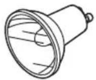
2 x Halogen light bulbs 120V 50W
natural_image
Isometric line drawing of a rectangular fence with vertical slats and two mounting holes (no text or symbols)Filters • 11 7/8" (301mm) • 13 7/8" (352mm)
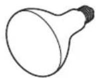
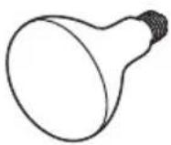
Infra-red heat lamp 120V 175W
Note: Above are the commonly used spare parts. To purchase these and any other spare parts please refer to your country specific section in the separate service and warranty book.
Accessories
natural_image
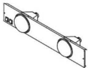
Technical line drawing of a mechanical component with two circular features and mounting brackets (no text or symbols)Heat lamp panel with 2x infra-red bulbs (175W each) and 3/4" (19mm) screws (2)
• 36" heat lamp panel (HIR36) (50080)
• 48" heat lamp panel (HIR48) (50081)
natural_image
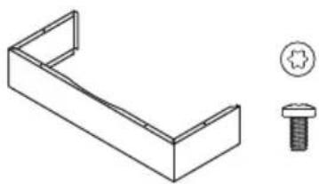
Technical line drawing of a U-shaped bracket with a bolt and mounting hole (no text or symbols)Duct covers (stainless steel) including 5/16" (8mm) T20 (TORX) machine head screws (6)
• 30"Duct cover 6" (152mm) high (50092)
• 36" Duct cover 6" (152mm) high (50076)
• 48" Duct cover 6" (152mm) high (50078)
• 30" Duct cover 12" (305mm) high (50093)
• 36" Duct cover 12" (305mm) high (50077)
• 48" Duct cover 12" (305mm) high (50079)

natural_image
Isometric line drawing of a rectangular block with a circular recess on top (no text or symbols)Duct transition 10" (254mm) outlet including 5/16" (8mm) T20 (TORX) machine head screws (12) (50129)
For details of your Manufacturer's Warranty and contacts for servicing, please refer to your separate service and warranty book provided with your range hood.
Complete and keep for safe reference:
Model
Serial No. ____
Purchase Date ____
Purchaser
Dealer ____
City ____
State ____
Zip ____
Country ____
Introduction 33
natural_image
Isometric line drawing of a rectangular electronic enclosure with two circular cutouts on top (no text or symbols)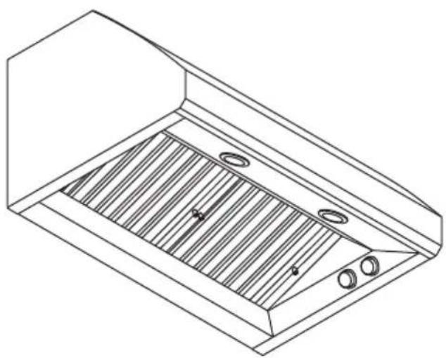
natural_image
Line drawing of a rectangular kitchen or oven with slatted ventilation duct and two circular fixtures (no text or symbols)MISE EN GARDE!
HCB30 = 66 lb (30 kg)
HCB36 = 75 lb (34 kg)
HCB48 = 99 lb (45 kg)
HC36 = 68 lb (31 kg)
HC48 = 84 lb (38 kg)
MISE EN GARDE!

natural_image
Isometric line drawing of a 3D mechanical housing or enclosure with two circular cutouts (no text or symbols)natural_image
Technical line drawing of a light bulb component with internal structure and top view (no text or symbols)Cheville murale (2)
natural_image
Technical line drawing of a mechanical component with screw and mounting bracket (no text or symbols)- HCB30-6 (1)
• HCB36-6 (1) - HCB36-12 (2)
- HCB48-12 (2)
HC36/48 (0)
natural_image
Isometric line drawing of a rectangular fence with vertical slats and two mounting holes (no text or symbols)Filtres
- HCB30 (2)
• HCB36/HC36 (2)
• HCB48/HC48 (3)
natural_image
Isometric line drawing of a rectangular mechanical component with internal slots (no text or symbols)Plateaux à graisse
- HCB30 (2)
• HCB36/HC36 (2)
• HCB48/HC48 (3)

natural_image
Simple 3D line drawing of a rectangular prism (no text or symbols)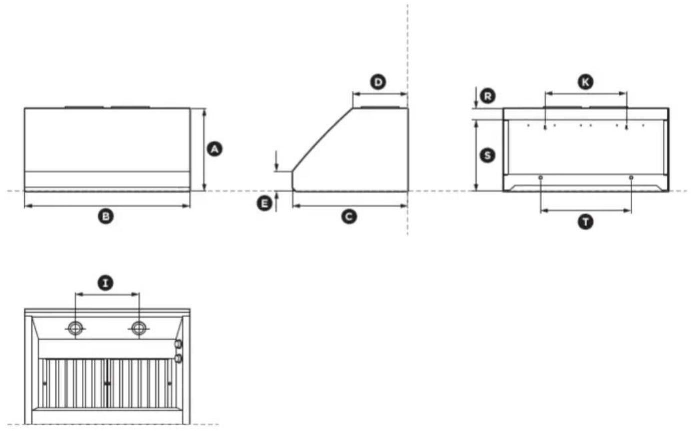
natural_image
Pure mechanical assembly diagrams showing two views of a bracket with no text or symbolsHauteur de la hotte
natural_image
Technical line drawing of a gas stove with cooling tower and fan (no text or symbols)natural_image
Isometric line drawing of a technical component with mounting brackets and circular features (no text or symbols)natural_image
Isometric technical drawing of a mechanical component with a circular feature and labeled part D (no text or symbols beyond label)natural_image
Isometric line drawing of a kitchen appliance with visible stove, oven, and doorways (no text or labels)INSTRUCTIONS D'INSTALLATION
natural_image
Technical line drawing of a rectangular electronic device with two circular cutouts and a shaded base (no text or symbols)natural_image
Technical line drawing of a rectangular electronic device with three circular components and labeled points (I, H), no readable text or symbols present.natural_image
Technical diagram of a mechanical assembly with a housing and internal components (no text or symbols)natural_image
Isometric technical diagram of a rectangular device with internal grating and mounting holes, labeled 'A' (no text or symbols on the diagram itself)
natural_image
Technical line drawing of a mechanical component with labeled section B (no text or symbols beyond label)natural_image
Diagram of a computer case with two connectors and internal components, showing fluid flow direction (no text or symbols)natural_image
Technical diagram of a heat exchanger or cooling unit with heat flow arrows and labeled component 'c' (no text or symbols beyond label)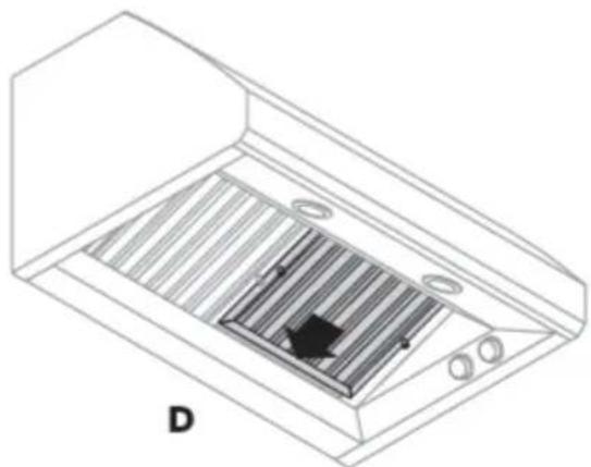
natural_image
Isometric technical diagram of a rectangular device with internal grating and mounting holes (no text or symbols)natural_image
Isometric line drawing of a rectangular metal panel with vertical slats and two mounting holes (no text or symbols)Filtres • 11 7/8 po (301 mm) • 13 7/8 po (352 mm)
Lampe infrarouge
120 V 175 W
natural_image
Isometric line drawing of a mechanical component with two circular cutouts and mounting brackets (no text or symbols)natural_image
Isometric line drawing of a rectangular block with a circular recess on top (no text or symbols)natural_image
Technical line drawing of a U-shaped bracket with a bolt and a small inset showing a cross symbol (no text or labels)© Fisher & Paykel Appliances 2018. All rights reserved.
The product specifications in this booklet apply to the specific products and models described at the date of issue. Under our policy of continuous product improvement, these specifications may change at any time. You should therefore check with your Dealer to ensure this booklet correctly describes the product currently available.

- HOTTE PROFESSIONNELLE
- IMPORTANT!
- SAVE THESE INSTRUCTIONS
- Registration
- WARNING!
- IMPORTANT SAFETY INSTRUCTIONS
- READ AND SAVE THESE INSTRUCTIONS
- General information
- Other required materials and tools:
- INSTALLATION PREPARATION
- Product dimensions
- Range hood width
- Determine installation location
- Height of the range hood
- Calculating the installation height
- Optional extras
- Duct covers
- Duct cover installation
- Duct transition
- Duct transition assembly
- Electrical requirements
- Venting requirements
- CAUTION!
- Make-up air (not included)
- Compatible blowers
- Wall mounting installation
- Cabinet mounting installation
- Internal blower installation (HCB30/36/48 range hood models only)
- Inline blower connection (HC36 and HC48 range hood models only)
- Electrical connection
- Range hood internal blower electrical connection (HCB30/36/48 models only)
- Complete the installation
- General operating information
- Cleaning
- General cleaning
- Filters and grease trays
- To remove the filters:
- Light bulb replacement
- To replace the light bulb:
- Replacing the infra-red heat lamp (optional accessory)
- Parts
- Accessories
- MISE EN GARDE!
- Hauteur de la hotte
- INSTRUCTIONS D'INSTALLATION
Brand : Fisher & Paykel
Model : HCB36-6N
Category : Range hood