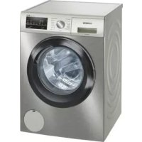
USER MANUAL iQ500 WM14UT6XES SIEMENS
3.2 Replacing the sealing ring 7
3.2.1 Removing the sealing ring.. 7 3.2.2 Installing the sealing ring 7
3.3 Replacing the tensioner for the front preparation 8
3.3.1 Removing the tensioner for the front preparation 3.3.2 Installing the tensioner for the front preparation...
3.4 Replacing the spring of the tensioner for the front preparation.. 9
3.4.1 Removing the spring of the tensioner for the front preparation.. 9 3.4.2 Installing the spring of the tensioner for the front preparation 9
3.5 Replacing the door 10
3.5.1 Removing the door... 10 3.5.2 Installing the door.. 10
3.6 Replacing the door components 11
3.6.1 Removing the door components 11 3.6.2 Installing the door components 11
3.7 Replacing the door seal 12
3.7.1 Removing the door seal 12 3.7.2 Installing the door seal 15
3.8 Replacing the door lock 16
3.8.1 Removing the door lock 16 3.8.2 Installing the door lock 17
3.9 Replacing the drum lighting.. 18
3.9.1 Checking the lighting of the drum 18 3.9.2 Mounting the lighting of the drum 18
Safety symbols and images that provide information about the type of danger.
This document uses the following safety symbols:
Torx TX20 wrench, 6.30mm (14") 152mm, for screws [00341272]
Search:
Disconnect the device from the power supply. Disconnect the device from the water supply.
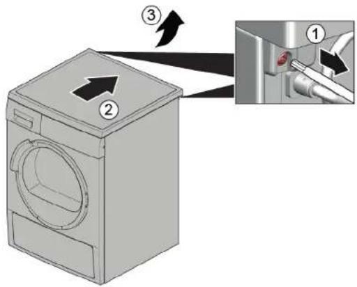
3.1.1 Removing the top work plate
1. Remove the screws (1). 2. Lift the top work plate towards the rear edge of the device (2). 3. Press the top work plate upwards (3) to remove it.
3.1.2 Mounting the top work plate
Mount in reverse order.

Repair
3.2 Replacing the fuse

ATTENTION
Sharp edges on the housing
Immediately disconnect

Tightening the tensioner.
Adjusting the tensioner.
Secure the tensioner against tightening.

CAUTION
Risk of injury from parts being thrown off by the screws!
Adjusting the tensioner part
Secure the component so that it does not fall.
WARNING
Risk of injury from parts being thrown off by the screws!
Replace the part of the tensioner or the customer's part, if necessary.
10.
Secure the component so that it does not fall.
Removal:
Remove the plug from the socket. Remove the plug from the power supply. The device is not working.→6 The device for the first preparation is connected.→8
3.2.1 Connecting the device
- 1. Connect the plugs (1).
2. Loosen the fastening elements (2, 3).

2. Loosen the control unit connection. 3. Connect the device.
3.2.2 Mounting the device
Mount the device.

Repair
3.3 Replacing the device for the first preparation
Removal:
Remove the plug from the socket. Remove the plug from the power supply.
3.3.1 Connecting the device for the first preparation
- Insert the device for the first preparation. 2.1. Press the button on the cover (1).
2. Connect the device for the first preparation (2).
3.3.2 Mounting the device for the first preparation
Mount the device back.
Repair
3.4 Removing the cover of the device for periodic preparation
Removal:
Before disconnecting from the power supply. Before disconnecting from the water supply. The device for periodic preparation is connected, -8
3.4.1 Removing the cover of the device for periodic preparation
1. Loosen the fastening elements.
2. Remove the cover of the device for periodic preparation.
3.4.2 Mounting the cover of the device for periodic preparation
Mount it in the reverse order.

Repair
3.5 Removing the door

CAUTION
Open the drain valve!
Adjustment/Gripping on the pipes
He nocaraTe KbM ObnactTa Ha naHTnTe.
Hocete npedna3HN pKabu.
N3nCKBaHe:
YpeBte n3KNIOUeHOT 3aXpaHbHeTo. YpeIbTe n3KJIoueH OT BoDcHa6nTEnHaTa MpeXa. Bpatata e otbopeha.
3.5.1 NbBaxDaHe Ha BpaTata
1.

BHIMAHHEI
Pnck ot nadaaun yactn nopadn pa3xna6eHN BHTOBE! NoBpeHa npTuHnHa ypeHa Nn B DoMa Ha KHeHTa, HAp. DbHOTO. 3akpenete KOMNOHHTa. Taka ye da He naDHe.

BHIMATEENHO
Pnck OT npdaun yactn nopadpa3xa6eHN BuHToBe!
HapaHbAhe npa ndaun yactn. 3akpenTe KOMnoHEHTa, Taka Ye da He naDHe.
CbaTe BHTOBete(1).
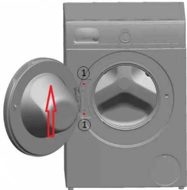
2.ИЗБаДЕТЕВРАТАНОРЕ.
3.5.2 MoHTIpaHe Ha BpaTaTa
MoHTnpaTBeBobpaTeHpeI.

3.6 Replacement of gate components
CAUTION
Open the area of the gate!
Crushing/pinching of fingers - do not touch the gate area. Wear protective gloves.
Requirement:
Disconnect the gate from the power supply. Disconnect the gate from the water supply. The gate is closed.→10
3.6.1 Removing the gate components
Open the gate fully outward.
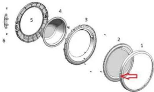
3.6.2 Mounting the gate components
Mount in reverse order.

Repair
3.7 Replacing the gate seal

CAUTION
Sharp edges - risk of injury
ATTENTION
Risk of injury to the upper part of the body when unscrewing the screws!
Press the upper part of the body.
Secure the component so that it does not fall.
ATTENTION!
Risk of injury to the upper part of the body when unscrewing the screws! Before starting work, unplug the device from the mains. Secure the component so that it does not fall.
Troubleshooting:
Set the circuit breaker to the off position. Set the circuit breaker to the off position. The mains connection is established for the first time. →8 The door is closed. →10 The cable gland is closed. →19
3.7.1 Closing the door
1.

I PRELIMINARY WARNING
Risk of crushing! Bone fractures/contusions and bruising when closing the door. Warning against crushing.
Lift the device up.
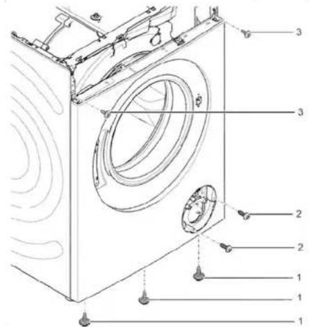
- Unscrew the screws in the lower part of the front panel (1).
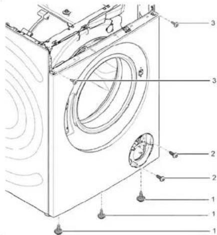
3. Remove the retaining screw.

Repair
- Remove the screws in the area of the plate (2).5.1. Loosen the screws at the rear of the device (1).
Risk of injury from moving parts if incorrectly installed!
Damage to or destruction of the device.
Tighten the clamping screws to the torque of the door 3.4 Nm.
Install the return.

Repair
3.8 Replacing the door hinge
As a manufacturer, we have not forgotten to provide the consumer with spare parts for the door, including repair instructions in accordance with Regulation (EC) 2019/2023. To ensure that the door hinge is replaced correctly, an electrical safety check must be carried out by a qualified electrician. Before carrying out any work, make sure that the device is disconnected from the power supply. This work must not be carried out by the user, but only by qualified personnel in accordance with the national regulations and standards.
DANGER
Risk of electric shock from live parts!
Danger to life from electric shock due to incorrect repair
Electrical work must only be carried out by qualified electricians. A safety check must be carried out in accordance with VDE 0701 and the national regulations.
CAUTION
Open the cover and pull the handle after preliminary adjustment.
ADJUSTMENT
The handle is not inclined! The locking mechanism/handle is adjusted by pulling the handle. Tighten the adjusting screw.
ATTENTION
Risk of falling parts during adjustment! Adjust the falling part. Secure the component so that it does not fall.
ATTENTION!
Risk of falling parts during adjustment! Adjust the handle on the client's door, if necessary. Secure the component so that it does not fall.
Adjustment:
The door is excluded from the closing sequence. The door is excluded from the water supply. The doors are freely accessible. The hinge pin is not connected. →6 The facade pin is connected. The rotating part is connected. →10 The hinges are connected. The hinge pin is connected. The door leaf is connected.
3.8.1 Connecting the door handle
- Exclude the intended door handle. 2. Release the door handle.
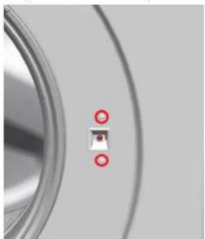
3. Connect the door handle.

Repair
3.8.2 Mounting the door handle
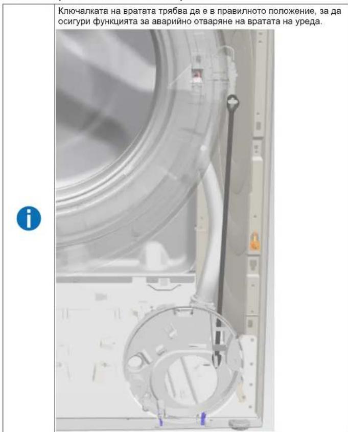
Mounting the return.
Risk of injury from falling parts! Tighten the screws!
Falling parts hazard
Secure the component so that it cannot fall.
WARNING!
Risk of injury from falling parts! Tighten the screws!
The part is located on the frame or on the client's body, e.g.
1.
Secure the component so that it cannot fall.
Removal:
The device is excluded from the warranty. The device is excluded from the warranty. The parts are freely accessible. The working pressure is not adjustable.→6 The warranty for the first repair is void.→8 The facade is not painted.
3.9.1 Replacing the drum lighting
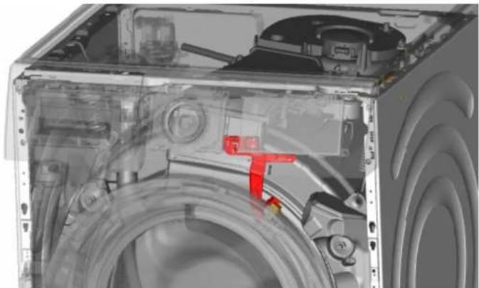
1. Remove the drum lighting holder. 2. Disconnect the electrical connections. 3. Replace the drum lighting holder.
3.9.2 Mounting the drum lighting
Mount in reverse order.

Repair
3.10 Adjusting the appliance feet
Warning:
Before adjusting, disconnect the appliance from the power supply.
3.10.1 Adjusting the appliance feet
Turn the feet by hand, turning them clockwise (2, 3).
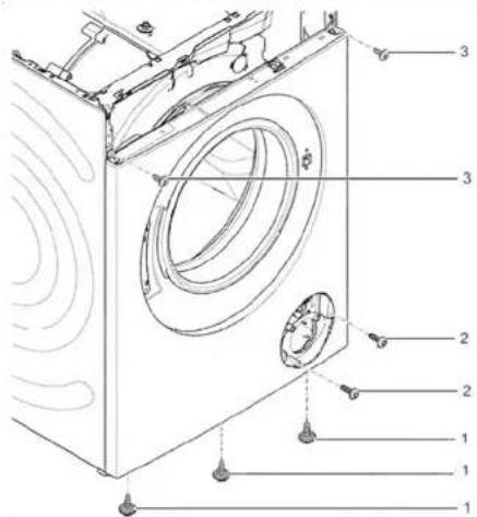
8. Adjusting the appliance.
3.11.2 Installing the appliance
Install the appliance.
Risk of falling parts.
Secure all individual components before falling.

Danger of falling parts due to loose screws!
Damage to other parts of the appliance or customer's household items, e.g., floor.
Secure all individual components before falling.
Requirement:
Make sure to secure the appliance against slipping.

Danger of falling parts due to loose screws!
Risk of injury from falling parts.
Make sure to secure the component against falling.


Danger of falling parts due to loose screws!
Make sure to secure the component against falling.
Presetting:
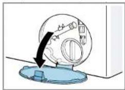
- Open the pump cover.
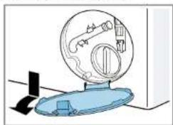
- Remove the pump cover.
Make sure to secure the devices against slipping.
Make sure to secure the component against falling.

Repair

NOTE!
Danger of falling parts due to loose screws!
Make sure to secure the component against falling.
Remove the screws on the front, starting from the bottom and working up (2, 3).
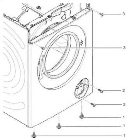
- Remove the front panel.
3.11.2 Installing the front panel
Repair hints - Washing machine
1 About this document. 108
1.1 Important information 108 1.1.1 Purpose 108 1.2 Explanation of symbols 108 1.2.1 Danger levels 108 1.2.2 Hazard symbols 108 1.2.3 Structure of the warnings.. 109 1.2.4 General symbols 109
Tools and aids 110
Repair 111
3.1 Replacing the worktop 111 3.1.1 Removing the worktop 111 3.1.2 Installing the worktop 111 3.2 Replacing the fascia panel 112 3.2.1 Removing the fascia panel 112 3.2.2 Installing the fascia panel 112
3.3 Replacing the detergent drawer 113
3.3.1 Removing the detergent drawer 113 3.3.2 Installing the detergent drawer 113
3.4 Replacing the detergent drawer handle 114
3.4.1 Removing the detergent drawer handle 114 3.4.2 Installing the detergent drawer handle 114
3.5 Replacing the door 115
3.5.1 Removing the door 115 3.5.2 Installing the door 115 3.6 Replacing door components 116 3.6.1 Removing door components 116 3.6.2 Installing door components 116
3.7 Replacing the door seal 117
3.10 Replacing pump cover 124
3.10.1 Removing pump cover 124 3.10.2 Installing pump cover 124
3.11 Replacing front panel 125
3.11.1 Removing front panel 125 3.11.2 Installing front panel 127
Concerning this document
1.1.1 Purpose
These repair hints support consumers to repair appliances by themselves according to the applicable eco-design regulation (as of 03/2021).
They contain information on how to exchange defined spare parts, including warnings and risks.
In case of questions, please contact our customer service. We will only be liable for damages if the repair hints have been followed properly.
1.2 Explanation of symbols
1.2.1 Danger levels
The warning levels consist of a symbol and a signal word. The signal word indicates the severity of the danger.
Table 1: Danger levels
| Warning level Meaning |
| Danger | Non-observation of the warning message will result in death or serious injuries. |
| Warning | Non-observation of the warning message could result in death or serious injuries. |
| Caution | Non-observation of the warning message could result in minor injuries. |
| Notice | Non-observation of the warning message could result in damage to property. |
1.2.2 Hazard symbols
Hazard symbols are symbolic representations which give an indication of the kind of danger.
The following hazard symbols are used in this document:
| Hazard symbol Meaning | |
| ! | General warning message |
| Danger from electrical voltage |
| Risk of explosion |
| Danger of cuts |
| Danger of crushing |
Concerning this document
| Hazard symbol Meaning | |
| Danger from hot surfaces |
| Danger from strong magnetic field |
| Danger from non-ionizing radiation |
Table 2: Hazard symbols
1.2.3 Structure of the warnings
Warnings in this document have a standardised appearance and a standardised structure.
Danger
Type and source of danger!
Possible consequences of ignoring the danger / warning.
Measures and prohibitions for preventing the danger.
The following example shows a warning that warns against electric shock due to live parts. The measure for avoiding the danger is mentioned.
Danger
Risk of electric shock due to live parts!
Death by electrocution
- Disconnect appliances from electrical supply at least 60 seconds before starting repairs.
1.2.4 General symbols
The following general symbols are used in this document:
| Gen. symbol Meaning | |
| 1 | Identification of a special tip (text and/or graphic) |
| i | Identification of a simple tip (only text) |
| Identification of a link to a video tutorial |
Table 3: General symbols
| Gen. symbol Meaning | |
| Identification of required tools |
| Identification of required preconditions |
| Identification of a condition (if ..., then ...) |
| Identification of a result |
| [Start]Identification of a key or button | |
| [00123456] Identification of a material number |
| Status Identification of displayed text / window(in the appliance's display) |

| Designation Details Images | |
| Auxiliary tool [15000155] | Tool for loosening out of plastic parts | |
| Screwdriver Torx T20 with bore hole [00340764] | 100 mm, for screws with safety pin | |
| Torque spanner [15000441] | Torque spanner 20 - 100 Nm | |
| Slot screwdriver [00340854] | Blade 3.5 mm x 0.6 mm x 100 mm, Protective Insulation 1000 V AC | |
| Slot screwdriver [00340855] | Blade 5.5 mm x 1.0 mm x 125 mm, Protective Insulation 1000 V AC | |
| Needle-nose pliers, angled pattern [00341269] | Length 200 mm | |
| Side-cutting pliers [00342182] | Length: 200 mm | |
| Designation Details Images | |
| Combination wrench [00340811] | Wrench size 10°mm, M6 | |
| Combination wrench [00340814] | Wrench size 13°mm, M8 | |
| Combination wrench [00340817] | Wrench size 17 mm, M10 | |
| Combination wrench [15000459] | Wrench size 16°mm, M10 | |

Repair
3.1 Replacing worktop
Required tools:
Torx Bit TX20 with hole, long 6.3 mm (1/4") 152 mm, for screws [00341272] with safety pin
Prerequisite:
Appliance is disconnected from power supply. Appliance is disconnected from water supply.
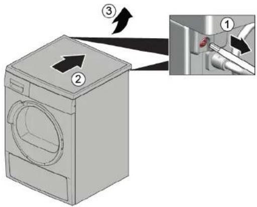
3.1.1 Removing worktop
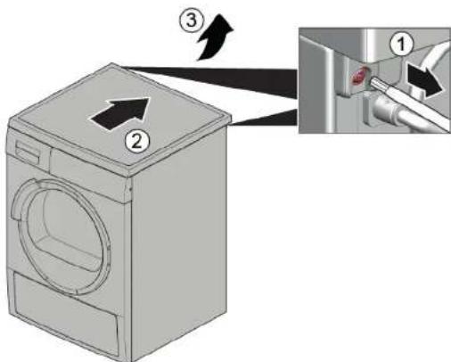
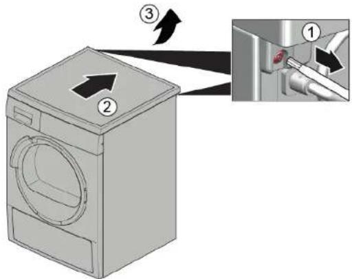
- Remove screws (1).
- Push worktop to the back of the appliance (2).
- Move worktop upwards (3) to remove it.
3.1.2 Installing worktop
Install in reverse order.

Repair
3.2 Replacing fascia panel

Sharp housing edges!
Cut injuries
Wear protective gloves.

Prerequisite:
Appliance is disconnected from power supply. Appliance is disconnected from water supply. Worktop has been removed. See page 111. Detergent drawer has been removed. See page 113.
3.2.1 Removing fascia panel
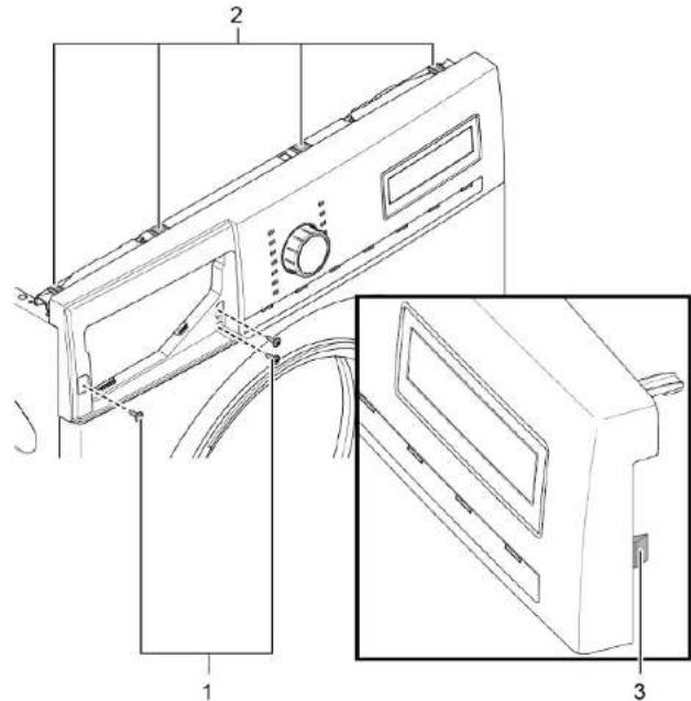
- Remove screws (1).
- Release catch elements (2, 3).
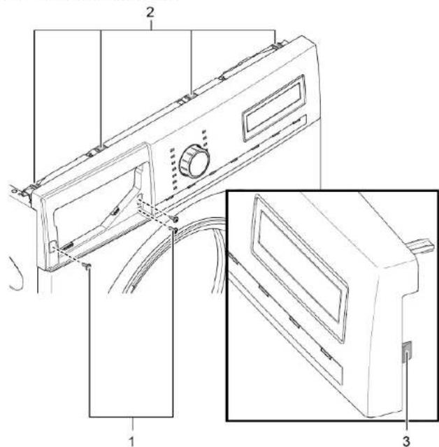
- Release plug contact of control unit.
- Remove fascia panel.
3.2.2 Installing fascia panel
Install in reverse order.

Repair
3.3 Replacing detergent drawer
Prerequisite:
Appliance is disconnected from power supply. Appliance is disconnected from water supply.
3.3.1 Removing detergent drawer
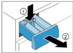
- Pull out detergent drawer. 2.1. Press down on insert (1)
2. Remove detergent drawer (2).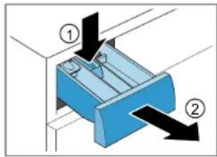
3.3.2 Installing detergent drawer
Install in reverse order.

Repair
3.4 Replacing detergent drawer handle
Prerequisite:
Appliance is disconnected from power supply. Appliance is disconnected from water supply. Detergent drawer has been removed. See page 113.
3.4.1 Removing detergent drawer handle
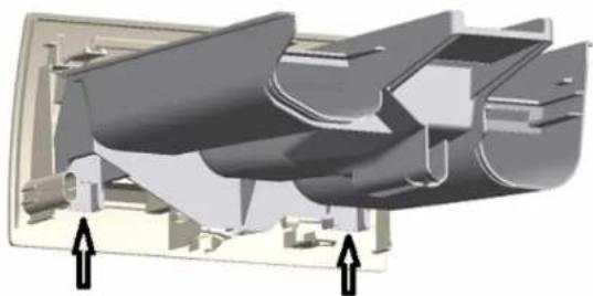
- Release catch elements.
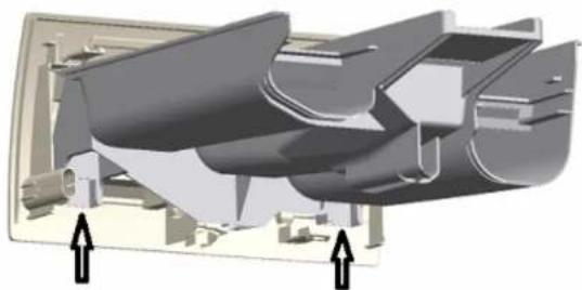
- Remove detergent drawer handle.
3.4.2 Installing detergent drawer handle
Install in reverse order.

Repair
3.5 Replacing door


Caution: Open hinge area! Finger crushing / entrapment. Do not reach into the hinge area. Wear protective gloves.
Prerequisite:
Appliance is disconnected from power supply. Appliance is disconnected from water supply. Door is opened.
3.5.1 Removing door
1.

Notice
Risk of falling parts due to released screws! Damage to other parts of the appliance or at customer's home, e.g. bottom - Secure component from falling down.


Risk of falling parts due to released screws!
Injury because of falling parts. - Secure component from falling down.
Remove screws (1).
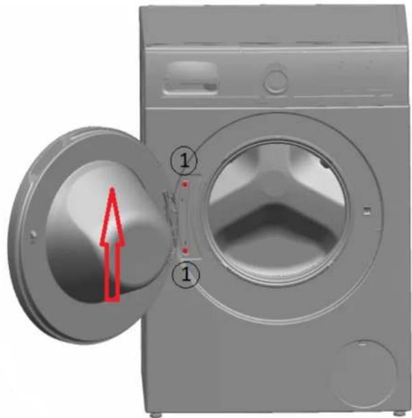
- Remove door upwards.
Install in reverse order.

Repair
3.6 Replacing door components
Caution
Open hinge area!
Finger crushing / entrapment Do not reach into the hinge area. Wear protective gloves.
Prerequisite:
Appliance is disconnected from power supply. Appliance is disconnected from water supply. Door has been removed. See page 115.
3.6.1 Removing door components
Disassemble door from outside to inside.
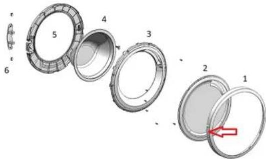
3.6.2 Installing door components
Install in reverse order.

Repair
3.7 Replacing door seal
Prerequisite:
The appliance is disconnected from the power supply. The appliance is disconnected from the water supply. The detergent drawer has been removed. (See page 113) The door has been removed. (See page 115) The pump cover has been removed. (See page 124)
Lift up the appliance at the front.
- Release the screws at the bottom of the front panel (1).
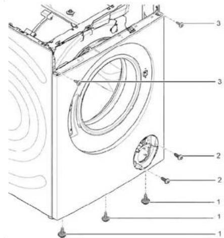
- Lower the appliance down.

Repair
- Remove the screws in the pump area (2). 5. 1. Release the screws at the back of the appliance (1).
- Remove the worktop (2, 3).

Repair
6.1. Remove the screws (1).
- Release the catch elements of the fascia panel (2, 3).
- Release the screws of the dispenser housing.
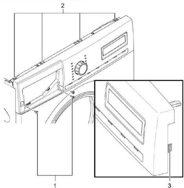
- Remove the fascia panel.
- Remove drum light holder at top.
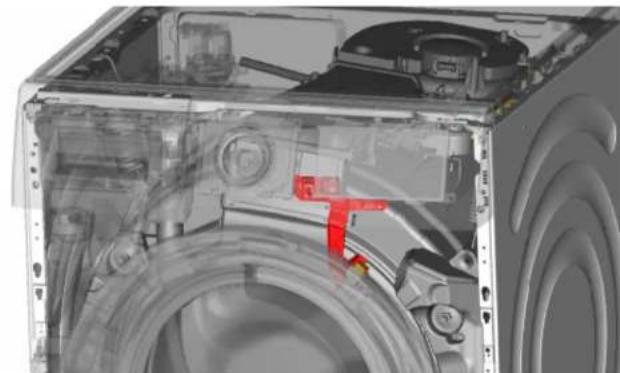


Notice
Risk of damaged surface! Surface of appliance can be scratched by using wrong tools. Only use plastic tools to replace the tension ring.
Remove tension ring from gasket with a plastic tool.
- Release door seal from front panel.
- Release cable connector from door lock.

Repair
- Release screws on top of front panel (3).
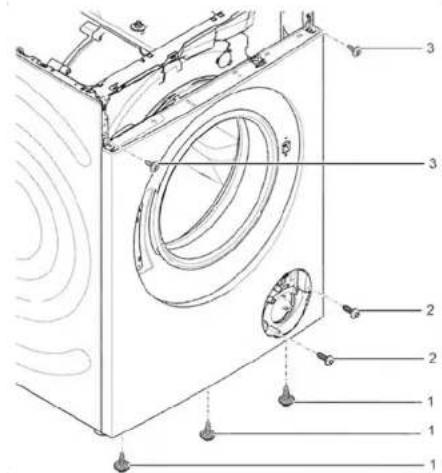
- Remove front panel.
- Release all hose connections.
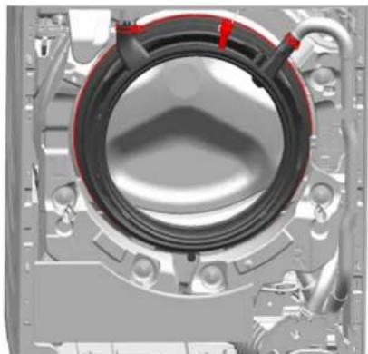
- Remove door seal.
Risk of falling parts due to incorrect installation! Injury or damage to the appliance.
Tighten tension ring of boot gasket with 3.4 Nm.
Install in reverse order.

Repair
3.8 Replacing door lock
As a manufacturer, we are obliged to provide consumers with the spare part door lock including repair instructions in accordance with Regulation (EU) 2019/2023. However, we would like to point out that after replacing a door lock, an electrotechnical safety test by a qualified electrician is required before the device is put into operation. This person must be verifiably qualified according to the country-specific laws, regulations and standards.

Risk of electric shock due to live parts!
Danger to life through electric shock in case of improper repair. After the repair, have a safety test according to VDE 0701 or country-specific regulations performed.

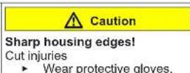
Sharp housing edges! Cut injuries. Wear protective gloves.

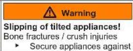
Slipping of tilted appliances!
Bone fractures / crush injuries - Secure appliances against slipping.

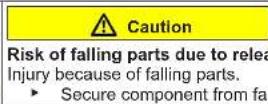
Risk of falling parts due to released screws! Injury because of falling parts. - Secure component from falling down.

Risk of falling parts due to released screws! Damage to other parts of the appliance or at customer's home, e.g., bottom. - Secure component from falling down.
Prerequisite:

Appliance is disconnected from power supply.

Appliance is disconnected from water supply.
Appliances is freely accessible. Worktop has been removed. → Page 111. Fascia panel has been removed. Door has been removed. → Page 115. Tension ring has been removed. Front panel has been removed. Door seal has been removed.
- Disconnect door lock plug.
- Release door lock.
3. Remove door lock.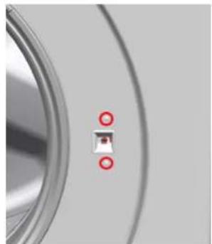

Repair
Install in reverse order.

Repair
3.9 Replacing drum light


Sharp housing edges!
Cut injuries
Wear protective gloves.

Slipping of tilted appliances!
Bone fractures / crush injuries
Secure appliances against slipping.

Risk of falling parts due to released screws!
Injury because of falling parts
- Secure component from falling down.

Risk of falling parts due to released screws!
Damage to other parts of the appliance or at customers home e.g. bot
tom.
Secure component from falling down.
Prerequisite:
Appliance is disconnected from power supply. Appliance is disconnected from water supply. Appliance is freely accessible. Worktop has been removed. (See page 111) Detergent drawer has been removed. (See page 113) Fascia panel has been removed.
3.9.1 Removing drum light
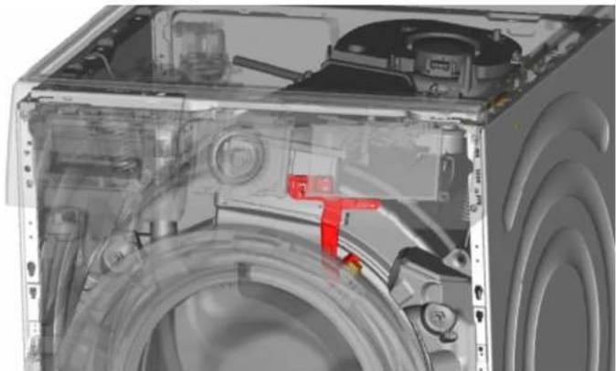
- Pull drum light holder out of appliance.
- Disconnect electrical connections.
- Remove drum light from drum light holder.
3.9.2 Installing drum light
Install in reverse order.

Repair
3.10 Replacing pump cover
Prerequisite:
Appliance is disconnected from power supply. Appliance is disconnected from water supply.
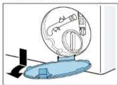
3.10.1 Removing pump cover
- Open pump cover.
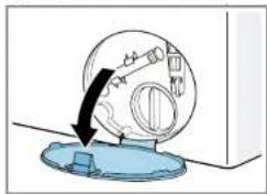
- Remove pump cover.
3.10.2 Installing pump cover
Install in reverse order.

Repair
3.11 Replacing front panel
Prerequisite:
Appliance is disconnected from power supply. Appliance is disconnected from water supply. Detergent drawer has been removed. See page 113. Door has been removed. See page 115. Door seal has been removed. Pump cover has been removed. See page 124.
3.11.1 Removing front panel
1.

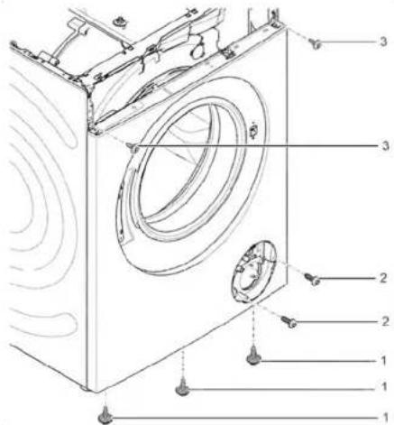
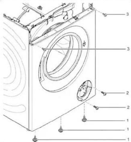
Lift up appliance at front.
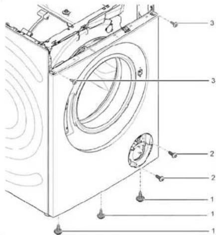
- Remove screws at bottom (1).
- Lower appliance down.

Repair
4.1. Remove screws (1).
- Push worktop to the back of the appliance (2).
- Move worktop upwards (3) to remove it.
5.1. Remove screws (1).
- Release catch elements (2, 3).
- Remove fascia panel.
7.

Caution
Risk of falling parts due to released screws! Injury because of falling parts.
Secure component from falling down.

Repair
Notice
Risk of falling parts due to released screws! Damage to other parts of the appliance or at customer's home, e.g., bottom.
Remove screws at front, beginning from bottom to top (2, 3).
- Remove front panel.
3.11.2 Installing front panel
Install in reverse order.
3.10 Replacing the pump cover 145
3.10.1 Removing the pump cover 145 3.10.2 Installing the pump cover 145
3.11 Replacing the front panel 146
3.11.1 Removing the front panel 146 3.11.2 Installing the front panel 148
About this document
1.1 Important information
1.1.1 Purpose
These repair instructions support the consumer in independently repairing devices in accordance with the applicable Ecodesign regulation (03/2021).
Table 1: Safety devices
1.2.2 Safety symbols
DANGER
Risk of electric shock due to live parts!
- Remove the front panel.
3.11.2 Install the front panel