1507016 - Soap dispenser BASETECH - Free user manual and instructions
Find the device manual for free 1507016 BASETECH in PDF.
| Product type | Automatic soap dispenser |
| Brand | BaseTech |
| Model | 1507016 |
| Power supply | 4 x 1.5 V C/LR14 batteries or 6 VDC, 800 mA power supply (not included) |
| Maximum power consumption | 350 mA |
| Standby current | 50 μA max. |
| Tank capacity | 1,000 ml max. |
| Dispensed amount (adjustable) | 0.25-0.3 ml or 0.5-0.6 ml |
| Sensor distance | 5-8 cm |
| Number of dispenses per battery set | Approx. 50,000 |
| Operating conditions | +10 to +50 °C, <90% RH |
| Storage conditions | 0 to +50 °C, <90% RH |
| Usage | Indoor only, enclosed rooms |
| Main functions | Automatic IR sensor dispensing, two quantity settings, level window, LED indicator |
| Maintenance and cleaning | Clean with a dry, lint-free cloth; do not use harsh agents, alcohol or chemical solutions |
| Safety | Keep out of reach of children, do not expose to moisture, use indoors only, observe battery polarity |
| Package contents | Soap dispenser, 5 screws, 5 wall plugs, key, instruction manual |
Frequently Asked Questions - 1507016 BASETECH
User questions about 1507016 BASETECH
0 question about this device. Answer the ones you know or ask your own.
Ask a new question about this device
Download the instructions for your Soap dispenser in PDF format for free! Find your manual 1507016 - BASETECH and take your electronic device back in hand. On this page are published all the documents necessary for the use of your device. 1507016 by BASETECH.
USER MANUAL 1507016 BASETECH
text_image
Technical diagram of a device with numbered parts labeled 4, 5, and 6
text_image
7 8 9 10 11
text_image
12 13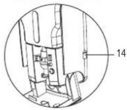
natural_image
Technical diagram of a mechanical assembly with numbered component (14), no readable text or symbols presentnatural_image
Technical diagram of a mechanical device showing internal components and a rotation arrow (no text or symbols)Abb. 1 Abb. 2
text_image
Technical diagram of a device with labeled parts, showing internal components and a hand interacting with the component.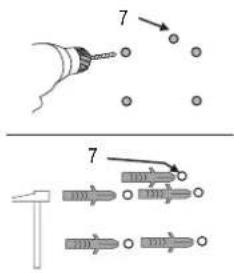
text_image
Diagram illustrating a mechanical or electrical assembly with numbered components and directional arrows, likely illustrating a step-by-step process.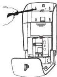
natural_image
Technical line drawing of a device interior with labeled components (no text or symbols)natural_image
Diagram of a device interior with labeled components and an inset showing a cable or connector (no text or symbols present)Abb. 6
natural_image
Diagram of a device interior showing internal components and a directional arrow (no text or symbols)Abb. 7 Abb. 8
natural_image
Technical line drawing of a mechanical device with an inset close-up view showing internal components (no text or symbols)Abb. 9
GB Operating instructions
Automatic soap dispenser
Item no. 1507016
Intended use
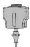
The product is designed for hygienic automatic dispensing of liquid soap. Once the hand is held under the sensor area, the soap foam is dispensed automatically. The transparent viewing window always shows the actual soap level. The product is operated on 4 x 1.5 V type C batteries or an external power adapter (batteries and power adapter are not included in the delivery).
It is intended for indoor use only. Do not use it outdoors. Never expose it to moisture.
For safety and approval purposes, you must not rebuild and/or modify this product. If you use the product for purposes other than those described above, the product may be damaged. In addition, improper use can cause hazards such as short circuiting, fire, electric shock etc. Read the instructions carefully and keep them. Make this product available to third parties only together with its operating instructions.
This product complies with the statutory national and European requirements. All company names and product names are trademarks of their respective owners. All rights reserved.
Delivery content
- Soap dispenser
- 5 x screw
- 5 x dowel
• Key
- Operating instructions
Latest operating instructions
Download the latest operating instructions via the link www.conrad.com/downloads or scan the QR code shown. Follow the instructions on the website.
Explanations of symbols

The lightning symbol inside a triangle is used when there is a potential risk of personal injury, such as electric shock.

An exclamation mark in a triangle indicates important instructions in this operating manual that absolutely have to be observed.

The arrow symbol indicates specific tips and advice on operation.
Safety instructions

Read the operating instructions carefully and especially observe the safety information. If you do not follow the safety instructions and information on proper handling in this manual, we assume no liability for any resulting personal injury or damage to property. Such cases will invalidate the warranty/guarantee.

a) General
- The device is not a toy. Keep it out of the reach of children and pets.
- Do not leave packaging material lying around carelessly. This may become dangerous playing material for children.
- Protect the product from extreme temperatures, direct sunlight, strong jolts, high humidity, moisture, flammable gases, vapours and solvents.
- Do not place the product under any mechanical stress.
- If it is no longer possible to operate the product safely, take it out of operation and protect it from any accidental use. Safe operation can no longer be guaranteed if the product:
- is visibly damaged,
- is no longer working properly,
- has been stored for extended periods in poor ambient conditions or
- has been subjected to any serious transport-related stresses.
- Please handle the product carefully. Jolts, impacts or a fall even from a low height can damage the product.
- Keep the product away from heat sources.
- Do not fill the soap tank with corrosive materials.
- Protect the soap tank from dust.
- This product is not waterproof and must not be installed in the shower.
- Only connect the power adapter to a normal mains socket connected to the public supply. Before plugging in the power adapter, check whether the voltage stated on the power adapter complies with the voltage of your electricity supplier.
- Never connect or disconnect power adapters if your hands are wet.


- Never unplug the power adaptor from the mains socket by pulling on the cable; always use the grips on the plug.
- When setting up the product, make sure that the cable is not pinched, kinked or damaged by sharp edges.
- Always lay the cables so that nobody can trip over or become entangled in them. This poses a risk of injury.
- For safety reasons, disconnect the power adapter from the mains socket during storms.
- When installing the product, make sure that the cables are neither kinked nor pinched.
- If the product will not be used for a long period of time, pull the power adapter out of the mains socket.
- If the wall plug transformer is damaged, do not touch it; there is danger to life from electric shock! First, switch off the mains voltage to the mains socket to which the wall plug transformer is connected (switch off at the corresponding circuit breaker or remove the safety fuse, then switch off at the corresponding RCD protective switch, so that all poles of the mains socket are disconnected). You can then unplug the wall plug transformer from the mains socket. Dispose of the faulty wall plug transformer in an environmentally friendly way; do not use it any more. Replace it with a wall plug transformer of the same design.
- The mains outlet must be located near to the device and be easily accessible.
- Consult an expert when in doubt about operation, safety or connection of the device.
- Maintenance, modifications and repairs are to be performed exclusively by an expert or at a qualified shop.
- If you have questions which remain unanswered by these operating instructions, contact our technical support service or other technical personnel.
b) Batteries
- Correct polarity must be observed while inserting the batteries.
- Batteries should be removed from the device if it is not used for a long period of time to avoid damage through leaking. Leaking or damaged batteries might cause acid burns when in contact with skin, therefore use suitable protective gloves to handle corrupted batteries.
- Batteries must be kept out of reach of children. Do not leave batteries lying around, as there is risk, that children or pets swallow them.
- All batteries should be replaced at the same time. Mixing old and new batteries in the device can lead to battery leakage and device damage.
- Batteries must not be dismantled, short-circuited or thrown into fire. Never recharge non-rechargeable batteries. There is a risk of explosion!
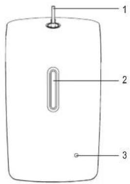
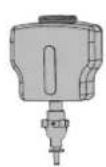
Operating controls
text_image
1 2 3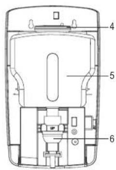
text_image
Technical diagram of a device with numbered parts labeled 4, 5, and 6
text_image
7 8 9 10 11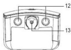
text_image
12 13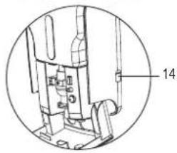
natural_image
Technical diagram of a mechanical assembly with numbered component (14), no readable text or symbols present1 Key and lock
2 Viewing window
3 LED indicator light
4 Soap tank lid
5 Soap tank
6 Foam pump
7 Opening for anti-theft screw
8 Fixing holes
9 Battery compartment
10 II/I/OFF switch
11 Discharge stop button
12 IR sensors
13 Discharge nozzle
14 6 V/DC, 800 mA power connector
Mounting
- Pay attention to the "Safety instructions" section.
- Select an appropriate installation location for the soap dispenser. There must be a free space of at least 40 cm under the soap dispenser. Only install the soap dispenser on a stable surface. Depending on the surface, suitable screws and dowels must be used.

drilling mounting holes or tightening screws, ensure that no cables or pipes (including water pipes) are damaged.
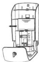
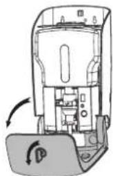
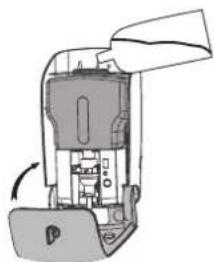
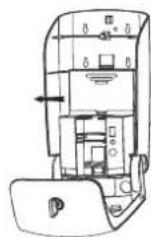
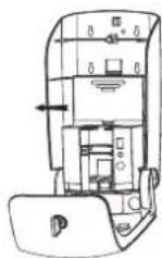
- Open the soap dispenser housing with the key (1) and fold it down.
- Remove the soap tank (5) pulling it out forward and set it aside.
natural_image
Diagram of a device interior showing internal components and a rotating button (no text or symbols)Fig. 1 Fig. 2
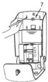
- Use the soap dispenser as a template and mark five drilling holes at the place of installation. Four of the fixing holes (8) are needed to hang the soap dispenser and the fifth opening (7) is intended for the locking screw. Use a level to hang the soap dispenser in a horizontal position.
- Now drill five holes in the marked points and insert the five dowels supplied. Make sure that the dowels fit flush with the wall without protruding.
- Insert four of the supplied screws into the drilled holes to hang the soap dispenser and screw them in using a suitable Phillips screwdriver. Let the screws protrude by several millimetres to be able to hang the soap dispenser. If the soap dispenser is located in a public area, insert also the fifth supplied screw into the opening for theft protection as an anti-theft screw (7) and screw it in. Caution! Do not overtighten the screw to prevent damage to the plastic housing.
text_image
Technical diagram of a device with labeled parts, showing hand operating a component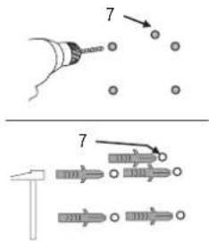
text_image
Technical diagram showing two-step assembly of a tool with numbered components and alignment instructions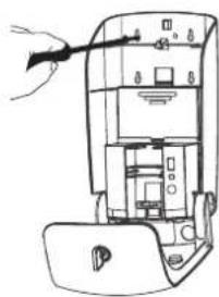
natural_image
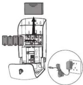
Line drawing of a device interior with labeled components and an arrow pointing to a component (no text or symbols present)- Open the battery compartment by pushing the lid upwards and insert four 1.5 V batteries of C/LR14 type, observing the correct polarity shown in the battery compartment. Close the battery compartment again.
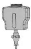
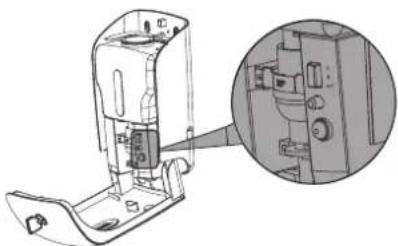
Alternatively, you can connect an appropriate power adapter to the 6 V/DC, 800 mA power connector (14) at the right side of the soap dispenser. The power adapter is not included in the delivery. To do this, open the cover piece of the connector and connect the power adapter to the 6 V/DC, 800 mA output (plug: length 12 mm, inner diameter 2.0 mm, outer diameter 5.5 mm).
natural_image
Diagram of a device interior with labeled components and an inset showing a close-up of a cable or connector (no text or symbols present)Fig. 6
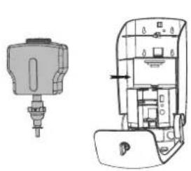
- Now put the soap tank back into the soap dispenser.
- Open the soap tank lid (4) and fill the soap dispenser with a suitable liquid soap. Take care not to overfill the soap dispenser (pay attention to the MAX. mark in the soap tank). You can always detect the actual soap level through the transparent viewing window. Replace the lid on the soap tank.
natural_image
Technical line drawing of a mechanical device with two views: one showing a cylindrical component and the other showing a multi-chamber device (no text or symbols)Fig. 7 Fig. 8
natural_image
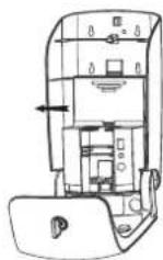
Diagram of a device interior showing internal components and a rotating arrow (no text or symbols)- Switch on the soap dispenser. The II/I/OFF switch (10) has three switching positions: Off, I and II. In the "OFF" position, the button is fully protruding and the soap dispenser is off. Press the switch once to set it to the "I" position. Each time the sensors respond, 0.25 to 0.3 ml of soap foam are dispensed. When you press the switch twice, it is set to the "II" position. Each time the sensors respond, 0.5 to 0.6 ml of soap foam are dispensed.
The discharge stop button (11) prevents the liquid soap from being dispensed when the soap dispenser is open. Once the housing is closed, the button is pressed and the liquid soap can be dispensed again.
natural_image
Technical line drawing of a device interior with an inset close-up view showing internal components (no text or symbols)Fig. 9
- Fold up the front part of the housing again. Close the soap dispenser and remove the key. The soap dispenser is now ready for use.
Operation
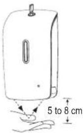
- The new soap dispenser must be operated by the IR sensors (12) a number or times so that the liquid soap can be dispensed at the discharge nozzle (13).
- Briefly hold out your hand under the automatic soap dispenser at a distance of 5 to 8 cm. The dispensing mechanism goes into operation and dispenses the preset amount of soap foam (either 0.25 to 0.3 ml or 0.5 to 0.6 ml). When the liquid soap is dispensed, the LED indicator light (3) glows red.
- When the batteries are low, the LED indicator light on the front side of the soap dispenser flashes every 3 seconds, prompting battery replacement. Replace the batteries as described in the chapter "Mounting", section 6. A set of batteries is sufficient for approx. 50,000 discharges.
text_image
5 to 8 cm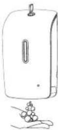
Care and cleaning
- Remove the batteries from the soap dispenser before cleaning.
- Disconnect the connected power adapter from both the socket and the soap dispenser.
- Do not use any aggressive cleaning agents, rubbing alcohol or other chemical solutions as they can cause damage to the housing and malfunctioning.
- Use a dry, lint-free cloth for external cleaning of the product (housing).
Disposal
a) Product

Electronic devices are recyclable waste and must not be disposed of in the household waste. At the end of its service life, dispose of the product according to the relevant statutory regulations.
Remove any inserted batteries and dispose of them separately from the product.
b) Batteries

As the end user, you are required by law (Battery Ordinance) to return all used batteries; they must not be disposed of in household waste!
Contaminated batteries are labelled with this symbol to indicate that disposal in household waste is prohibited. The designations for the heavy metals involved are: Cd = Cadmium, Hg = Mercury, Pb = Lead (the designation is on the batteries, e.g. below the trash symbol on the left).
Used batteries can be returned free of charge to collection points in your municipality, our stores or wherever batteries are sold.
You thus fulfil your statutory obligations and contribute to the protection of the environment.
Technical data
Battery operation 6 V/DC (4 x 1.5 V/DC type C/LR14 batteries)
Power connector....6 V/DC, 800 mA
Power consumption....max. 350 mA
Standby power consumption .... max. 50 μA
Discharge amount (2 settings)....0.25 - 0.3 ml / 0.5 - 0.6 ml
Sensor distance....5 - 8 cm
Soap tank filling capacity....max. 1000 ml
Operating conditions....+10 to +50 °C, <90 % RH
Storage conditions....0 to +50 °C, <90 % RH
Dimensions (W x H x D) 160 x 285 x 117 mm
Weight 1.13 kg
F Mode d'emploi
text_image
Technical diagram of a device with numbered parts labeled 4, 5, and 6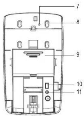
text_image
7 8 9 10 11
text_image
12 13
natural_image
Technical diagram of a mechanical assembly with numbered component (14), no readable text or symbols presentnatural_image
Diagram of a device interior showing internal components and a scroll arrow (no text or symbols)Fig. 1 Fig. 2
text_image
Technical diagram of a device with labeled parts, showing hand operating a component
text_image
Technical diagram showing two-step assembly of a tool with numbered components and alignment instructions
natural_image
Line drawing of a device interior with labeled components and an arrow pointing to a component (no text or symbols present)natural_image
Diagram of a device interior with labeled components and an inset showing a close-up of a cable or connector (no text or symbols present)Fig. 6
natural_image
Diagram of a device interior showing internal components and a directional arrow (no text or symbols)Fig. 7 Fig. 8
natural_image
Technical line drawing of a mechanical device with an inset close-up view showing internal components (no text or symbols)Fig. 9
Dimensions (L x H x P)....160 x 285 x 117 mm
Poids....1,13 kg
text_image
Technical diagram of a device with numbered parts labeled 4, 5, and 6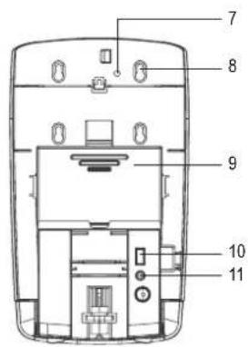
text_image
7 8 9 10 11
text_image
12 13
natural_image
Technical diagram of a mechanical assembly with labeled component 14 (no text or symbols beyond label)natural_image
Diagram of a device interior showing internal components and a directional arrow (no text or symbols)Afb. 1 Afb. 2
text_image
Technical diagram of a device with labeled parts, showing hand operating a component
text_image
Technical diagram showing two-step assembly of a tool with numbered components and arrows indicating motion or assembly steps.
natural_image
Line drawing of a device interior with labeled components and an arrow pointing to a component (no text or symbols present)natural_image
Diagram of a device interior with labeled components and an inset showing a close-up of a cable or connector (no text or symbols present)Afb. 6
natural_image
Technical line drawing of a mechanical device with two views: one showing a cylindrical component and the other showing a multi-chamber device (no text or symbols present)Afb. 7 Afb. 8

natural_image
Diagram of a device interior showing internal components and a directional arrow (no text or symbols)natural_image
Technical line drawing of a mechanical device with an inset close-up view showing internal components (no text or symbols)Afb. 9