Termo Charme Plus - Pan Cola - Free user manual and instructions
Find the device manual for free Termo Charme Plus Cola in PDF.
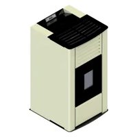
| Product type | Pellet stove with hot water production |
| Brand | Cola |
| Model | Termo Charme Plus |
| Nominal power | 21.2 kW |
| Heating volume | Up to 517 m³ (depending on insulation) |
| Fuel | Certified wood pellets (DIN plus, EN ISO 17225-2, Ö-Norm M 7135) |
| Power supply | 230 V ~ 50 Hz |
| Protection fuse | 2 A on main switch |
| Control panel | Backlit LCD screen with buttons and status LED |
| Remote control | Infrared with 4 or 6 buttons (battery CR2025 or P23GA) |
| Hydraulic connection | Flow and return 3/4" male, city water inlet 1/2" female |
| Flue gas evacuation | Diameter 80 mm, vertical flue with anti-wind cowl |
| Combustion air intake | Diameter 50 mm, min. cross-section 100 cm² |
| Hydraulic circuit pressure | 1.1 to 1.5 bar (closed expansion vessel), safety valve at 3 bar |
| Safety thermostat | Tank > 85 °C, chamber > 95 °C (resettable) |
| Flue overpressure safety | Safety valves above the heat exchanger |
| Sensors | Flue temperature probe, water temperature probe, ambient temperature probe, vacuum switch, flowmeter |
| Programming | Daily, weekly, weekend timer with 4 programs |
| Standby mode | Yes, with automatic restart (ΔT 2 °C by default) |
| Cleaning | Brazier daily, ash drawer every 2-3 days, glass, heat exchangers by shaking turbulators |
| Periodic maintenance | Annual flue cleaning, extraordinary maintenance every 1800 h or 2000 kg of pellets |
| Included accessories | Power cable, manual, opening key, remote control |
| Compliance standards | EN 60335-1, EN 60335-2-102, EN 14785, CE, DoP |
Frequently Asked Questions - Termo Charme Plus Cola
User questions about Termo Charme Plus Cola
0 question about this device. Answer the ones you know or ask your own.
Ask a new question about this device
Download the instructions for your Pan in PDF format for free! Find your manual Termo Charme Plus - Cola and take your electronic device back in hand. On this page are published all the documents necessary for the use of your device. Termo Charme Plus by Cola.
USER MANUAL Termo Charme Plus Cola
natural_image
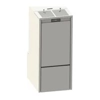
Exterior view of a modern beige industrial water heater with ventilation grilles and a black glass door (no text or symbols visible)484215370-M5_01/2016
Hardware - M
Read the instructions carefully before installation, use and maintenance.
The manual is an integral part of the unit.
COLA guarantees its products, except for parts subject to normal wear, in accordance with the current regulations. For the warranty terms, please contact the importer or the authorised agent who can integrate the compulsory warranty period with an additional period under his sole and exclusive responsibility.
The product warranty is invalidated for any trouble, breakage or accident due to failure to comply with or apply the instructions provided in this manual.
FR 62 - 88
Declaration of Performance according to Regulation (EU) n° 305/2011
Unique identification code of the product type:
Model and/or batch no. and/or series no. (Art 11-4):
Intended uses of the construction product, in accordance with the applicable harmonised technical specification:
Residential space heating appliance with water fired by wood pellets.
Name or trademark of the manufacturer (Art. 11-5):
+39.045.6144043 / +39.045.6144048
Name and address of the agent (Art. 12-2):
Assessment and verification system for constancy of performance (Annex V):
Notified laboratory:
N° Test report under system 3:
1/2 - DoP_LSANX00Y_IT-EN-F-D-ES
8 Prestazione dichiarata / Declared performance / Performance déclarée / Erklärte Leistungen / Prestaciones declaradas
| Specifica tecnica armonizzataHarmonized technical specificationSpécifications techniques harmoniséesHarmonisierte technische SpezifikationEspecificación técnica armonizada | EN 14785:2006 | ||
| Caratteristiche EssenzialiEssential characteristicsCaractéristiques essentiellesWesentliche MerkmaleCaracterísticas esenciales | PrestazionePerformancePerformanceLeistungenPrestación | ||
| Reazione al fuoco / Reaction to fire / Résistance au feu / Feuerbeständigkeit / Resistencia al fuego : A1 | |||
| Distanza da materiali combustibiliDistance to combustible materialsDistance de sécurité aux matériaux combustiblesAbstand von brennbarem MaterialDistancia de mat. combustible | Minime distanze / Minimum distances / Distance minimumMindestabstand / Distancia mínima [mm] :posteriore / rear / arrière Rückseite / revés = 200lati / sides / côté / Seite / lado = 200frontale / front / avant / Vorderseite / frente = 1000soffitto / ceiling / plafond / Decke / techo = 1000pavimento / floor / sol / Boden / fondo = 0 | ||
| Rischio di fuoriuscita di braci incandescenti / Risk of burning fuel falling outRisque de fuite de combustibile / Gefahr Brennstoffaustritt / Riesgo de perdida de combustible | Conforme / CompliantConforme / konform / Conforme | ||
| Emissione di prodotti della combustioneEmission of combustion productsÉmission des produits de combustionEmission von VerbrennungsproduktenEmisiones de productos de combustión | Alla potenza termica nominaleNominal heat output/Puis.nomNennleistung / Potencia nominal | Alla potenza termica ridottaReduced output/Puissance réd.Red.Leistung/Potencia reducida | |
| CONOxOGCPM | 0,006% - 80,2 mg/Nm ^3 141,8 mg/Nm ^3 1,6 mg/Nm ^3 11,9 mg/Nm ^3 | 0,010 % - 121,8 mg/Nm ^3 152,6 mg/Nm ^3 1,1 mg/Nm ^3 4,3 mg/Nm ^3 | |
| Temperatura superficiale / Surface temp. / Temp.de surface/ Oberflächentemperatur/Temp.superficial | Conforme / CompliantConforme / konform / Conforme | ||
| Sicurezza elettrica / Electrical safety / Sécurité électrique / Elektrische Sicherheit / Seguridad eléctrica | Conforme / CompliantConforme / konform / Conforme | ||
| Pulibilità / Cleanability/ Facilité d'accès et nettoyage/Zugänglichkeit und Reinigung / Accesibilidad y limpieza | Conforme / CompliantConforme / konform / Conforme | ||
| Pressione massima di esercizio / Max operating pressure / Pression maximale de serviceMaximaler Betriebsdruck / Presión máxima de trabajo | 2 bar | ||
| Temperatura fumi a potenza termica nominale / Flue gas temperature at nominal heat outputTemp.des funée à la puissance nominale/Rauchgastemperatur Nennleistung /Temp.de humos a Pot.nominal | 145,5 °C | ||
| Resistenza meccanica ( per sopportare un camino-canna fumaria)/Mechanical resistance ( to carry a chimney/flue )/Résistance mécanique (pour soutenir la cheminée) / Mechanische Festigkeit (um den Kamin zu tragen) / Resistencia mecánica (de soporte de la chimenea) | NPD ( Nessuna Prestazione Determinata /No Performance Determined / Aucune performance déterminée)Keine Leistung festgestellt / Prestación no determinada ) | ||
| Prestazioni termiche / Thermal performance / Performance thermiqueThermische Leistungen / Prestaciones térmicas | Alla potenza termica nominaleNominal heat output/PuissancenomNennleistung / Potencia nominal | Alla potenza termica ridottaReduced output/Puissance réd.Red.Leistung/Potencia reducida | |
| Potenza introdotta/ Heat input/ Puis.introduite/ Eingefuhrt Leistung / Pot.introducida | 22,83 kW | 5,77 kW | |
| Potenza nominale/ Nominal heat output / Puis. nominale/ Nennleistung / Pot. nominal | 21,2 kW | 5,5 kW | |
| Pot. resa in ambiente / Room heating output / Puissance rendeu à l'ambientUmgebung gelieferteLeist. / Potencia suminis.entorno | 3,1 kW | 0,68 kW | |
| Potenza ceduta all'acqua / Water heating output / Puissance rendue al'eauDem Wasser gelieferte Leist./ Potencia cedida al agua | 18,1 kW | 4,82 kW | |
| Rendimento / Efficiency / Rendement / Wirkungsgrad / Rendimiento | 92,88 % | 95,28 % | |
The performance of the product identified in points 1 and 2 is in conformity with the declared performance in point 8.
This declaration of performance is issued under the sole responsibility of the manufacturer identified in point 4.
Signed for and on behalf of the manufacturer
2/2 - DoP_LSANX00Y_IT-EN-F-D-ES
CE
The following harmonised standards or technical specifications (designations) which comply with good engineering practice in safety matters in force within the EEC have been applied:
As the manufacturer's authorised representative established within EEC, we declare under out sole responsibility that the equipment follows the provisions of the Directives stated above.
CE MARKING INFORMATION
INFORMATIONS RELATIVES AU MARQUAGE CE
natural_image
Technical line drawing of a mechanical device with an arrow indicating leftward motion and a warning symbol (no text or labels present)natural_image
Exterior view of a door with control panel and door lock (no visible text or symbols)text_image
G S W 55°C SET E T P A C 9 U A 28°C SET E T P A i b i E n t E4.4.2 Pulizia del braciere
text_image
Diagram of a remote control panel with labeled icons including Wi-Fi, plus signs, thermometer, and power buttonTasto P3: Accensione-spegnimento stufa
Tasto P1: Aumento temperatura ambiente
natural_image
Line drawing of a remote control device with icons for signal, power, and function buttons (no text or labels)text_image
Diagram showing various industrial warning symbols and an arrow pointing to a black vertical bar, likely indicating a warning or safety symbol.natural_image
Close-up of a metallic cylindrical container filled with dark granular material, possibly a container or mold (no visible text or symbols)Braciere sporco
natural_image
Close-up of a perforated metal pipe or vent with a circular opening (no text or symbols visible)Braciere pulito
natural_image
Close-up of a dark, square mechanical component with a central knob, placed on a metal tray (no visible text or symbols)natural_image
Technical line drawing of a mechanical device with internal components and directional arrows indicating movement (no text or symbols)6 MANUTENZIONE
6.1 Premessa
text_image
Technical diagram of a refrigerator internal structure with numbered components for identification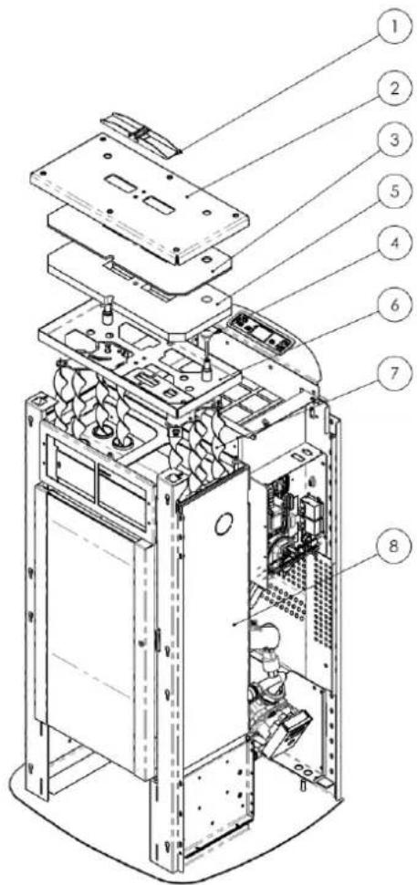
text_image
Exploded view diagram of a server rack with numbered components for identificationtext_image
Technical diagram of a server rack with numbered components for identificationLegenda :
text_image
Technical diagram of an industrial machine with numbered components for identification7 RICERCA GUASTI
1.9. Stove decommissioning
1.10. Instructions for requesting assistance and replacement parts
2. TRANSPORT AND INSTALLATION
2.1. Packing, handling, shipment and transport
2.2. Place of installation, positioning and fire-prevention safety
2.3. Air inlet
2.4. Fume exhaust
2.4.1. Types of installation
2.5. Brazier and turbulator position check
2.6. Electrical connection
2.7. Wiring diagram
2.8. Wiring diagram for zone system
2.9. Plumbing connections
2.10. Emergency
3. STOVE SAFETY
3.1. Safety distance from flammable materials.
3.2. Fume exhaust safety
3.3. Combustion chamber overpressure safety
3.4. Overheating - pellet hopper temperature safety thermostat
3.5. Safety against flare-back in the pellet chute
3.6. Overcurrent electrical protection device
3.7. Power failure safety
3.8. Water circuit overpressure safety
4.2. Description of control panel
4.3. Lighting
4.3.1 Check before lighting
4.3.2 Startup stage
4.4. Work stage
4.4.1 Modifying the water-room temperature setting
4.4.2 Cleaning the brazier
4.4.3 Water heater with heat exchanger quickly
4.4.4 Water heater with storage tank
4.4.5 System with puffer / heat storage
4.5 Shutting down
4.6 Menu
4.6.1 menu 01 – Chrono setting
4.6.2 menu 02 – User adjustments
4.6.3 menu 03 – User setting
4.6.4 menu 04 – Boiler status
4.6.5 menu 05 – Technician settings
4.7 Remote control
4.7.1 replacing the battery
4.8 Thermostat – external chronothermostat
4.9 Idle period (end of season)
5 STOVE CLEANING
5.1 Cleaning the brazier
5.2 Cleaning the ash pan
5.3 Cleaning the glass
5.4 Cleaning the fume extractor and combustion chamber
5.5 Cleaning the air flow meter
5.6 Cleaning the ceramic surfaces (ceramic models)
5.7 Cleaning the flue - flue connection
5.8 Cleaning the exchanger with turbulator-shaker device
6 MAINTENANCE
6.1 Introduction
6.2 Removing the ceramic cladding
6.3 Removing the steel cladding
6.4 Stove internal parts
6.5 Electrical components
6.6 Plumbing components
7 TROUBLESHOOTING
7.1 Alarm management
8 INSTALLER
8.1 Menu installer settings
1 GENERAL INFORMATION
1.1 Introduction
Dear Customer,
First of all we wish to thank you for the trust placed in us by purchasing one of our products. Please read and carefully follow the advice given in this installation, use and maintenance manual in order make best use of the product.
All the documents regarding the unit's certifications or declarations, in particular the Declaration of Conformity and Declaration of Performance, can be found through the website of the relevant trademark.
1.2 Using the manual
The Manufacturer reserves the right to make technical or aesthetic changes to the products at any time without notice.
Stove installation, use and maintenance operations must comply with the requirements given in this manual as well as the European, National, Regional, Provincial and Municipal regulations.
The drawings, measurements, diagrams and any other configurations are given only by way of example.
This manual is an integral part of the product; make sure it always stays with the stove, even if sold, transferred to another owner or installed in another place, so that it can be consulted at any time.
If lost or damaged, ask the Authorised Service Centre for a copy so that the stove always has its own manual.
| This symbol indicates the presence of an important message; failure to pay attention to it can result in serious damage to the stove and even injury | |
| Pay special attention to “words in bold face” |
1.3 Safety rules.
- Read the use and maintenance manual before installing, lighting and servicing the stove.
- Have installation, the electrical connection, testing and maintenance carried out by a qualified and/or authorised technician.
- Connect the stove to an approved flue by means of an inspectionable terminal; several units can be connected only if allowed by the local regulations and by the flue inspection Body.
- Connect the stove to the suction system by means of a pipe or air inlet from outside.
- Connect the stove to an approved 230 V-50 Hz electrical socket.
- With the TERMO model, connect the unit to the heating system; under no circumstances can it be used without the water connection and without water in the heating chamber.
- Make sure the electrical system and the sockets are suitable for the maximum absorption of the unit, specified on the label and in this manual.
- The stove must be unplugged and cold before carrying out any maintenance.
- Do not use flammable liquids or substances to light the stove or rekindle the flame: when the stove is lit, pellet ignition is automatic.
- The pellet stove must only be fed with wood pellets having the characteristics described in this manual.
- The stove must not be used as an incinerator.
- Never block the combustion air inlet and fume outlet openings.
- Do not handle easily flammable or explosive substances near the stove while it is operating.
- Do not remove the pellet hopper protection grille.
- Do not operate the stove with the fire door open and/or the glass damaged or broken.
- During operation the intense heat generated by combustion of the pellets makes the external surfaces of the stove very hot, and in particular the fire door, handle and flue pipe. Therefore avoid contact with these parts without suitable protection.
- Keep objects that are flammable and/or not heat resistant at a suitably safe distance.
- Clean the brazier regularly every time the stove is lit or whenever reloading pellets.
- Avoid the creation of smoke and unburnt products during lighting and/or normal operation; an excessive accumulation of unburnt pellets in the brazier must be eliminated manually before relighting the stove.
- Have the pipe and smoke baffles inside the combustion chamber cleaned regularly by qualified personnel.
- Warn children and guests about the hazards described above.
- In case of operation problems, the stove can be relit only after eliminating the cause of the problem.
- Any tampering and/or unauthorised replacements with non-original parts of the stove can create a risk for the user's safety and relieves the manufacturer of any civil or penal liability.
- Only use original replacement parts recommended by the manufacturer.

The manufacturer declines any liability for problems, damage or accidents caused by failure to follow or apply the instructions contained in this manual.
1.4 Technical description
The stove works exclusively on pellets and enables easy installation with the heating system. The stove's automatic control systems guarantee optimum heat output and complete combustion; there are also safety systems to guarantee safe operation for the stove parts and for the user.
When correctly installed, the unit works in any outside climatic conditions, and in any case in critical conditions (strong wind, frost, etc.) the safety systems can cut in, shutting down the stove.
The stove model TERMOCHARME PLUS with nominal power of 21,2 kW ensures a maximum heatable volume of 517 m3, considering the coefficient of a building's energy requirements equal to 35 W/m3, and may vary depending on the insulation, type and climatic zone which are important variables for the correct choice of unit. For technical data, refer to the table on page 8.
TERMOCHARME PLUS pellet heating stove dimensions
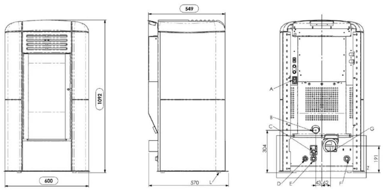
Key:
A - Power cable connection
B - Combustion air inlet
C - Water drain in overpressure (1/2" female)
D - Water supply connection
E - System return (3/4" male)
F - System delivery (3/4" male)
G - ∅80 mm fume exhaust pipe connection
H - Control panel model F047
I - Pellet hopper door
L - Adjustable feet
M - Turbulator shaker knobs
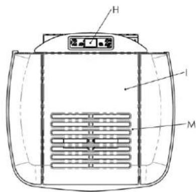
text_image
H I M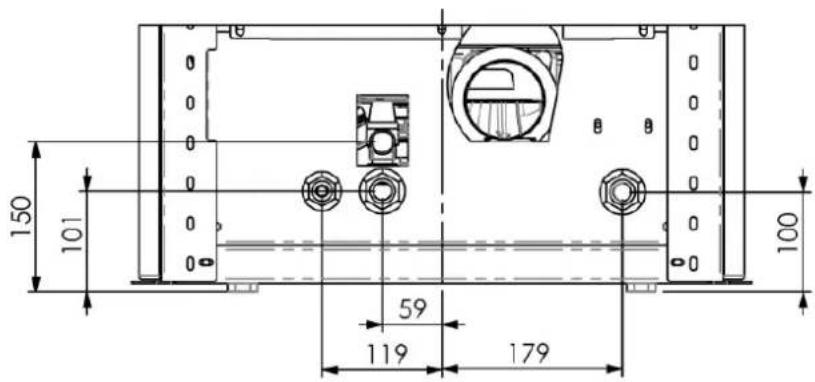
text_image
150 101 59 119 179 100DETAIL Z SCALE 1:7,5
TERMOCHARME PLUS pellet heating stove fire door opening - closing
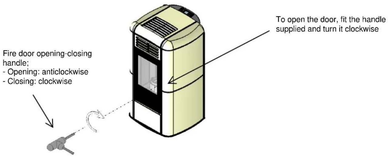
text_image
Fire door opening-closing handle; - Opening: anticlockwise - Closing: clockwise To open the door, fit the handle supplied and turn it clockwise1.5 Permissible use and fuel
The pellet stoves work exclusively on pellets in different types of wood complying with Standard DIN plus 51731 or UNI EN ISO 17225-2 or Ö-Norm M 7135 or having the following characteristics:
| Heat value | min. 4.8 kWh/kg (4180 kcal/kg) |
| Density | 680-720 kg/m3 |
| Moisture | max. 10% weight |
| Diameter: | 6 ±0.5 mm |
| Ash percentage | max. 1.5% weight |
| Length: | min. 6 mm- max. 30 mm |
| Composition: | 100% untreated wood from the wood industry or post consumer without added binding substances or bark, complying with current regulations |
| Packing | in bags made from environmentally friendly or biodegradable material or paper |
The pellet hopper is at the back of the stove. The door opening is positioned to slide and is located in the top part and loading occurs manually with the stove on or off, making sure not to overfill and operate in complete safety. The use of pellets with characteristics different from those tested by the technician during first lighting involves a new setting of the boiler pellet loading parameters; this operation is not covered by the warranty.

- Store the pellets in a dry place.
- For reasons of regular and efficient operation, pellets or other fuels cannot be manually loaded in the brazier
- Do not load non-conforming fuels in the hopper.
- Do not load foreign bodies such as containers, boxes, bags, metals, etc., in the hopper.
- The use of poor quality and non-conforming pellets damages and compromises stove operation, invalidating the warranty with the exclusion of liability of the manufacturer.
1.6 Accessories supplied
The supply includes:
Electrical power cable;
Installation, use and maintenance manual;
Opening - closing key;
Remote Control.
natural_image
Technical line drawing of a mechanical device with an arrow indicating leftward motion and a warning symbol (no text or labels)1.7 Reference standards
Standard UNI 10683:2012 : Standard UNI EN14785:2006 :
Installation requirements for heat generators burning wood or other solid biofuels; Requirements for design, manufacture, construction, safety and performance, instructions and marking, together with the relevant test methods for approval of units burning pellets;
Standard CEI EN 60335-1 : Safety of electrical appliances for domestic and similar use - part 1;
Standard CEI EN 60335-2-102 : Safety of electrical appliances for domestic and similar use - part 2;
Standard CEI EN 55014-1 : Electromagnetic resistance - Requirements for electrical appliances, electric tools and similar electric equipment - Part 1: Emission of interference;
Standard CEI EN 55014-2 : Electromagnetic resistance - Requirements for electrical appliances, electric tools and similar electric equipment - Part 2: Immunity; Product family standard;
Standard CEI EN 61000-3-2 : Limits for harmonic current emissions (Input current ≤16 A per phase);
Standard CEI EN 61000-3-3 : Limitation of voltage fluctuations and flicker in low voltage supply systems for equipment with nominal current ≤ 16 A;
Standard CEI EN 62233 : Measuring methods for electromagnetic fields of electrical household appliances and similar with reference to human exposure.
Standards DIN plus 51731 – UNI EN ISO 17225-2 - Ö-Norm M 7135 : Standards regarding the specifications and
classification of pellets.
1.8 Dataplate
The data plate is located on the inside of the pellet hopper door or on the back of the stove. It gives all the stove's characteristic data, including the manufacturer's details, serial number, CE marking, test laboratory and the Declaration of Performance reference number.
1.9 Stove decommissioning
When definitively deciding to not to use the stove any more, we recommend to disconnect the power supply and to empty the pallet tank completely. In order to eliminate the stove, it is necessary to packaged it with a strong packaging and then take contact with local organisation which follows the selling off operations respecting the local rules. Otherwise we recommend to back the stove directly to the distributor when buying a similar new one.
The picture of the bin crossed is labelled on the equipment, and it means that when the device is out of use it has to be kept separated by other wastes.
1.10 Instructions for requesting assistance and replacement parts
To request any assistance and/or replacement parts contact your dealer, area importer or the nearest authorised service centre, clearly specifying the following: stove model, serial number, date of purchase, list of replacement parts, details of faults or malfunctioning.

- All operations on components must be carried out by authorised and/or qualified personnel.
- Make sure all electrical connections are disconnected and that the stove is cold before any work on it.
- Only use original replacement parts.
2 TRANSPORT AND INSTALLATION
2.1 Packing, handling, shipment and transport
The stove complete with packing can be lifted using a lift truck, inserting the forks (of suitable length) in the special spaces in the wooden pallet. Make sure the equipment used for lifting and transport can take the weight of the stove, specified on the dataplate and in this manual.
Avoid taking the load in areas where it could be a danger if dropped.
Open the packing, remove the stove from the pallet and position it in the required place, making sure it complies with that provided for.
Set the stove down on the floor carefully without bumping and position it in the required place. Make sure the floor can take the weight of the stove, otherwise consult a specialised technician.
Disposal or recycling of the packing must be carried out by the end-user in compliance with the current local regulations.
2.2 Place of installation, positioning and fire-prevention safety
The place of installation must be sufficiently ventilated to allow the removal of any combustion smoke leaks.
The unit is suitable for operation in domestic environments with min. temperature of 0^ C; it comes complete with an antifreeze function that activates the heating pump for system water temperatures below 6^ C, safeguarding: the heating chamber, heating/DHW circuit. The antifreeze function is active only when the stove is electrically powered.
To prevent the risk of fire, the structures surrounding the stove must be protected from the heat. For example, floors in wood or flammable material must be suitably protected with steel panels or toughened glass. Any wooden boards or beams above or crossed by the flue must be suitably protected in conformity with the requirements of the specific current installation standards. Suitable fire-prevention devices should be arranged for any eventuality.
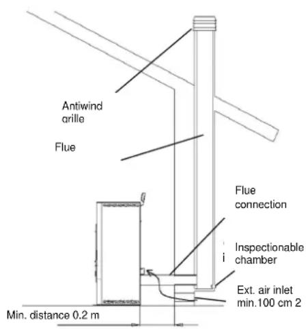
The minimum front distance for the protection of flammable objects is 1 m. The minimum safety distances from flammable materials must be at least 0.2 m and in any case comply with the following table:
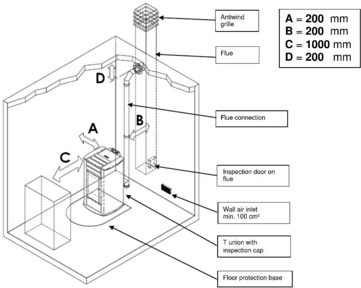
text_image
Antiwind grille Flue A = 200 mm B = 200 mm C = 1000 mm D = 200 mm Flue connection A B C Inspection door on flue Wall air inlet min. 100 cm² T union with inspection cap Floor protection baseEvery installation must provide for an easily accessible technical space for periodical maintenance.
The stove is provided with 4 adjustable feet to facilitate positioning on not perfectly flat floors. To adjust the height, tilt the stove slightly and turn the feet as required.
The stove is supplied with the ambient sensor fixed through a wrapper on the back of the stove; we recommend to remove the wrapper and to locate the sensor in the best position possible as to improve the temperature registration in accordance with the ambient context and the length of the cable.
As for temperature registration done at a certain distance we recommend to install the ambient thermostat/ambient programming clock-thermostat – see. par.4.8.

- The stove cannot be installed in bedrooms, bathrooms and in general in rooms where another heating unit is already installed without an independent air inflow.
- With wooden floors, install a floor protection base in conformity with the current regulations. Suitable fire-prevention devices should be arranged for any eventuality.
- Do not install the stove in places with an explosive atmosphere.
2.3 Air inlet
The stove air inlet pipe or intake is located at the back and is round and 50 mm in diameter.
The combustion air can be sucked:
from the room, provided there is a wall air inlet near the stove, communicating with the outside and of minimum area 100 cm ^2 suitably protected externally by a grille;
or with connection directly to the outside with a suitable pipe of inside diameter 50 mm and max. length 1.5 m.
2.4 Fume exhaust
Fumes can be exhausted through a connection to a conventional flue.

- The installer must check the efficiency and state of the flue and its conformity with the local, national and European regulations.
- Certified pipes and connections with adequate seals guaranteeing their tightness must be used.
- In case of fire, shut down the stove, promptly call the fire department, and avoid continual attempts to extinguish it.
2.4.1 Types of installation
Listed below are definitions and requirements for correct installation of an exhaust flue in accordance with Italian Standard UNI10683:
FLUE : a vertical duct for collecting and expelling, at an appropriate height from ground, the fumes coming from a single unit and, where permitted, more than one.
FLUE technical requirements :- it must be fumetight, isolated and insulated depending on its use;
- it must have a mainly vertical path with axis deviation <45^ ;
- it must be at a suitable distance from flammable materials with insulation or air gap;
- it must preferably have a constant, free and independent round internal section;
- it is advisable for the flue to have an inspectionable chamber for the collection of solid materials
- and any condensate, placed under the beginning of the fume duct.
text_image
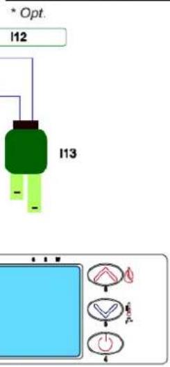
Antiwind arille Flue Flue connection Inspectionable chamber Ext. air inlet min. 100 cm 2 Min. distance 0.2 mFLUE CONNECTION or DUCT: duct or connection element between the unit and flue for evacuation of fumes.
DUCT technical requirements: - it must not cross rooms in which the installation of combustion units is not allowed;
- flexible metal tubes or fibre cement pipes are prohibited;
- the use of counter-sloping elements is prohibited;
- horizontal sections must have an upward slope of at least 3°;
- the length of the horizontal section must be minimal and not more than 3 m;
- there must not be more than 3 changes of direction, without the T union;
- with change of direction >90^ a max. of 2 bends can be used with length in horizontal projection not exceeding 2 m
- the fume duct must have a constant section and allow the recovery of soot.
CHIMNEY CAP: a device placed on the top of the flue to facilitate the dispersion of fumes into the atmosphere.
CHIMNEY CAP technical requirements: - it must have a section equivalent to that of the flue;
- it must have a useful section not less than double the internal section of the flue;
- it must prevent the entry of rain and foreign bodies and ensure the discharge of fumes in any atmospheric condition;
- it must ensure an adequate dilution of fumes and be positioned outside the backflow area;
- it must be without mechanical means of suction.
- it must have a useful section not less than double the internal section of the flue; - it must prevent the entry of rain and foreign bodies and ensure the discharge of fumes in any atmospheric condition; - it must ensure an adequate dilution of fumes and be positioned outside the backflow area; - it must be without mechanical means of suction.

The direct discharge of fumes must take place on the roof and not towards closed spaces (even open air).
2.5 Turbulator and baffle position check
Before lighting the stove make sure the brazier is in the correct position, i.e. fitted in the special slots. Also make sure the turbulator shaker device is resting in a lower position. An incorrect position of the brazier and/or turbulators can result in malfunctioning and excessive blackening of the glass.

At every stove lighting check the correct position of the brazier and turbulator shaker device.
2.6 Electrical connection
Connect one end of the power cable to the rear socket of the stove, and the other to the wall socket.
The voltage supplied by the system must match that specified on the stove dataplate and in the technical data section of this manual.
During stove idle periods it is advisable to remove the power cable.

-Make sure the electrical system is equipped with an earth and differential switch in accordance with the current Regulations.
-The power cable must never touch the stove exhaust pipe.
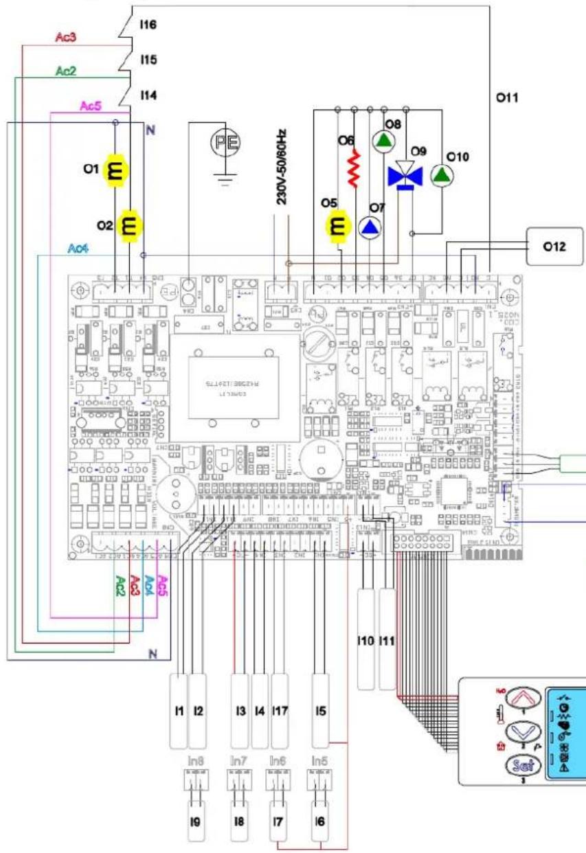
2.7 Wiring diagram
text_image
Ac3 I16 I15 Ac2 I14 Ac5 N O1 E O2 E O4 230V-50/60Hz O6 O8 O9 O10 O5 E O7 O11 O12 SLLAPEST 380CZHE LETSWG3 AC2 AC3 AC4 AC5 N I1 I2 I3 I4 I17 I5 In8 In7 In6 In5 I9 I8 I7 I6 IN1 IN2 IN3 IN4 IN5 IN6 IN7 IN8 IN9 IN10 IN11 SET| 01 | Fume extraction fan |
| 02 | Auger's motor |
| 03 | - |
| 04 | - |
| 05 | Auger's motor additional tank * NOT AVAILABLE |
| 06 | Igniter |
| 07 | Heating pump coupled to 3 ways valve 09 |
| 08 | Heating pump coupled to second pump 010NOT AVAILABLE |
| 09 | Three ways motor valve *Sanitary pump coupled to heating pump 08 *NOT AVAILABLE |
| 010 | |
| 011 | Safety circuit |
| 012 | Boiler consent AUX * |
| I1 | Water probe safety boiler (S1) |
| I2 | Water probe heating (S2) |
| I3 | Fume probe |
| I4 | Room thermostat / Puffer heating thermostat * |
| I5 | Water pressure tranducer |
| I6 | Level pellet 1 NOT AVAILABLE |
| I7 | Level pellet 2 * NOT AVAILABLE |
| I8 | Water probe sanitary boiler (S3) * |
| I9 | Flowswitch / thermostat sanitary boiler * |
| I10 | BUS 1 * |
| I11 | BUS 2 * |
| I12 | Fume verifier encoder |
| I13 | Air flow meter |
| I14 | Pressure switch |
| I15 | Thermostat safety pellet |
| I16 | Thermostato safety water |
| I17 | Room probe* |
flowchart
graph TD
    A["I12"] --> B["I13"]
    B --> C["Display Panel"]
    style A fill:#f9f,stroke:#333
    style B fill:#ccf,stroke:#333
    style C fill:#cfc,stroke:#333
2.8 Wiring diagram for zone system
Before installing the heating stove in the house, check the type of heating system;
in case of several zones, a special electronic controller for multi-zone circuits, available as an optional, must be installed. This is to prevent overheating of the heating chamber due to possible simultaneous closing of the zone valves and consequent stopping of hot water flow.
2.9 Plumbing connections
The heating capacity of the unit must be previously established by calculating the building's heat requirement according to current regulations. The system must be provided with all the components for correct and regular operation; in fact according to the rules of proper workmanship in installation, shutoff valves and non-return valves allowing the stove to be isolated in case of maintenance and/or checks, must be interposed between the stove and the heating system.
Proceed slowly during heating chamber water filling, to allow correct and complete evacuation of the air from the vent (for a closed vessel system from 1.1 to 1.5 bar).
The pellet stove has an internal heating circuit complete with circulating pump, safety valves, air vent, temperature probes and pressure transducer.
If the heating system is managed in zones a multi-zone controller, available on request, must be installed.
To display the boiler's water circuit pressure, just press the control panel button P5 for 3 seconds.

During stove transport the gaskets in the plumbing system may come loose and/or break, causing water leaks during normal operation; therefore make sure to check the tightness of the circulating pump and heating chamber connection rings and vent the residual air during water filling and after the first hours of operation.
To connect the stove to a heating system it is advisable to contact a competent technician in order to best optimise the plumbing connections and the performance of the entire system without compromising stove operation.
One of the following optionals must be requested for the connection to the DHW circuit:
- a monostable 3-way valve for installing outside the stove.
After completing the DHW connection it is necessary to access the technical menu of the control and select the type of circuit; every specific DHW function set: DHW EXCHANGER, BOILER or DHW BOILER appears on the display at the moment of heating-DHW switchover with one of the messages given below and remains until the end of the DHW request by the thermostat or flow switch :
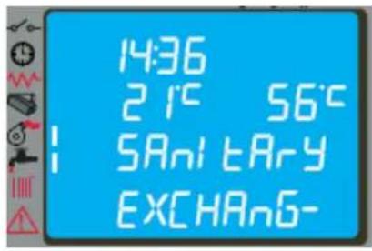
text_image
14:36 21°C 56°C 5Anl tAry EXCHAn6-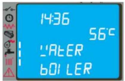
text_image
14:36 56°C LATER BOL LER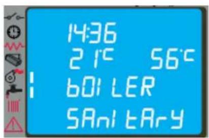
text_image
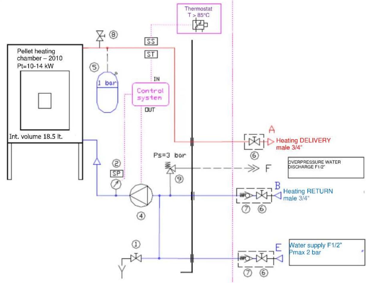
14:36 21°C 56°C 60 LER SANitaryHydraulic diagram - heating pellet stove ref. COLA 10-14kW-06-2010
Heating pellet stove
flowchart
graph TD
    A["Pellet heating chamber - 2010 Pt=10-14 kW"] --> B["Int. volume 18.5 lt."]
    B --> C["Control system"]
    C --> D["Thermostat T > 85°C"]
    D --> E["SS"]
    D --> F["ST"]
    E --> G["⑧"]
    F --> H["⑤"]
    G --> I["1 bar"]
    H --> J["IN"]
    I --> K["OUT"]
    J --> L["PS=3 bar"]
    K --> M["A Heating DELIVERY male 3/4""]
    L --> N["⑥"]
    M --> O["F OVERPRESSURE WATER DISCHARGE F1/2""]
    N --> P["B Heating RETURN male 3/4""]
    P --> Q["⑦ ⑥"]
    Q --> R["E Water supply F1/2" Pmax 2 bar"]
    R --> S["①"]
    S --> T["Y"]
    T --> U["② SP"]
    U --> V["④"]
    V --> W["⑨"]
    W --> X["Overpressure water discharge F1/2""]
KEY

Drain cock

Pressure sensor / Pressure gauge

Circulating pump

Membrane pressure vessel

Shutoff valve / Cock

Non-return valve

Circuit / heating chamber air ven

Safety valve P max 3 bar

Safety sensor T > 85°C

Water temperature sensor

Circuit pressure sensor

Valves to be included in system during installation – not supplied with the unit
* *
Arrangement
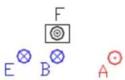
PLUMBING CONNECTIONS on back of stove
2.10 Emergency
Suitable fire-prevention devices should be arranged for any eventuality. In case of a fire, proceed as follows:

- Immediately disconnect the plug.
- Extinguish the fire using fire-extinguishers (powder).
- Call the fire department immediately.
- Do not use jets of waters to extinguish the fire.
3 STOVE SAFETY
3.1 Safety distance from flammable materials
To prevent the risk of fire, stove positioning must respect a minimum distance from flammable materials, according to that given in the technical table of the manual and on the dataplate.
Pay attention to the type of floor: for delicate and flammable materials it is advisable to use plates in steel or toughened glass as a support base (see section 2 - Transport and Installation). In case of particularly fragile objects such as furniture, curtains or sofas, increase the stove distance considerably.
3.2 Fume exhaust safety
In normal operation the combustion chamber is in a negative pressure, guaranteeing seal against possible smoke leaks in the room. If a certain vacuum level is not reached or the fume exhaust outlet is blocked, the vacuum switch detects the lack of a negative pressure inside the combustion chamber or the air flow meter detects a lack of air flow and, through the electronic controller, switches off the auger rotation motor, signalling the anomaly with a message on the control panel 'AL8 NO NEG PRESS' or 'AL9 INSUF DRAUGHT'.
3.3 Combustion chamber overpressure safety
Any and/or sudden overpressures in the combustion fumes inside the chamber and fume exhaust ducts are discharged by opening of the safety valves located on the heat exchanger. During normal operation these valves are kept closed by their weight and the negative pressure in the combustion chamber, guaranteeing a seal against any smoke escaping.

Periodically check closing, the integrity of the device and its operation.
3.4 Overheating - safety thermostats
natural_image
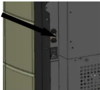
Close-up of a door panel with a black arrow pointing to the left side (no visible text or symbols)On the front and bottom of the hopper, and precisely on the pellet chute and on the top part of the heating chamber, there are two temperature probes connected to the respective safety thermostats that automatically shut off the pellet supply in case of excessive heating. In this case the extractor and/or fans continue working, allowing the stove to cool down rapidly. The fault is displayed on the control panel with a message 'AL 7 THERMAL SAF'. In case of activation, proceed as follows:
▶ Allow the stove to cool down for at least 45 minutes.
▶ Reset the thermostat by pressing the button near the switch on the back of the stove (figure opposite).
▶ Restart the stove normally.
Pellet hopper thermostat activation temperature : > 85°C
Heating chamber thermostat activation temperature : > 95°C
3.5 Safety against flare-back in the pellet chute
The solutions preventing flare-back are:
▶ negative pressure in the combustion chamber see par. 3.2.
▶ the siphon shape of the pellet chute.
▶ the hopper temperature safety see par. 3.4.
3.6 Overcurrent protection device
The unit is protected against overcurrent by 2A fuses on the power supply of the main stove switch located at the back.
3.7 Power failure safety
A temporary power failure does not limit stove safety and the hopper temperature does not reach high values (< 85°C), given the small quantity of pellets burning in the brazier.
This anomaly can result in some smoke briefly escaping into the room, which does not involve any risk.

Do not tamper with the safety devices.
3.8 Plumbing circuit overpressure safety
A possible overpressure of the water inside the chamber, by P>3 bar, is discharged through activation of the safety valve installed in the plumbing system inside the stove.

Do not tamper with the safety devices.
3.9 Fume extractor fan failure
If the fume extractor fan stops for any reason, the electronic controller instantly stops the pellet feed, displaying the message 'AL4 FAN FAIL'.
4 STOVE USE
4.1 Introduction
The pellet stove has the advantage of combining the heat generated by the combustion of wood with the convenience of automatic water temperature management and the possibility of weekly programming of switching on/off, as well as the connection of a thermostat and/or chronothermostat and start-stop remote control.
For safe and reliable use:
- when lighting and using the unit the first time, unpleasant odours may be created, therefore air the room thoroughly;
- the hopper must only be filled with good quality pellets; make sure the bag does not come into contact with the hot surfaces of the stove ;
- do not put any fuel other than the prescribed pellets in the hopper;
- the unit must not be used as a waste incinerator;
- the boiler must only operate with the fire door always closed.
- the fire and ash door seals must be checked periodically to prevent air from entering;
- to ensure thermal efficiency and correct operation it is necessary to clean the brazier every time pellets are loaded;
- when lighting the stove for the first time, allow it to heat up gradually by setting low operating temperatures (see the section on temperature setting);
- during lighting, operation and shutdown, the stove may creak a little due to the heat expansion.
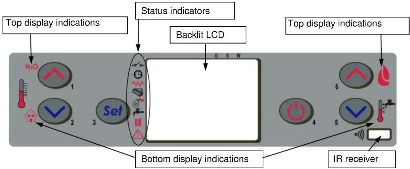
4.2 Description of control panel
The control panel comprises a backlit LCD, on/off button 'P4', SET/MENU button 'P3', four menu buttons 'P1', 'P2', 'P5', 'P6', and seven stove operation status LEDs.
flowchart
graph TD
    A["Top display indications"] --> B["H2O"]
    B --> C["1"]
    B --> D["2"]
    B --> E["3"]
    F["Bottom display indications"] --> G["Set"]
    G --> H["4"]
    G --> I["5"]
    G --> J["6"]
    K["Backlit LCD"] --> L["G S W"]
    M["IR receiver"] --> N["Ground"]
    style A fill:#f9f,stroke:#333
    style F fill:#f9f,stroke:#333
    style K fill:#ccf,stroke:#333
The panel enables stove lighting and shutdown, adjustment during operation and the setting of management and maintenance programmes. The display shows all the information on stove operation status.
To access the menus, proceed as follows:
- press the SET button 'P3';
- press the buttons 'P5', 'P6' repeatedly to scroll the various menus;
- press one of the increase/decrease buttons 'P1', 'P2', to set the required parameter;
- press the SET button 'P3' to confirm the parameter value.
On accessing the menu it is possible to obtain the various types of displays and carry out the available settings depending on the access level. Given below is the table of controls and respective messages displayed during programming or setting operation parameters:
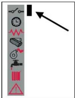
The Figure opposite describes the meaning of the status indicators in the left part of the display.
Activation of one of the segments on the display signals activation of the corresponding device according to the list opposite.
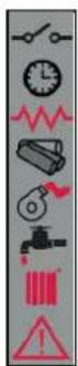
External contact
Chrono
Electrical element
Auger
Fume extractor
HEATING circuit activation
ALARM
4.3 Lighting
4.3.1 Check before lighting
Before lighting the stove:
- make sure to have read and understood the information given in the manual;
- follow the oral instructions on operation of the unit provided by the installer prior to use.
- the hopper must be filled with pellets;
- the combustion chamber must be clean;
- the brazier must be completely free, cleaned of any combustion residuals and correctly fitted in the brazier holder;
- check hermetic closing of the ash box and fire door;
- check the connection of the power cable and switching to ON/1 of the switch located on the back of the stove.
- check opening of the delivery and return shutoff valves as well as the water circuit pressure.

- At first startup, remove all the components that could burn (instructions/label) from the stove firebox.
- Any lighting done after long idle periods requires the removal of any residual pellets that have remained inside the hopper, in being damp fuel no longer suitable for combustion, and complete cleaning of the combustion chamber.
4.3.2 Startup stage
To light the stove, press the button 'P4' for 3 seconds: the message 'START' will appear on the display.
This stage is automatic and managed entirely by the electronic controller without the possibility of changing the parameters.
Alternatively the stove can be lit by pressing the buttons P4 and P5 together for 3 seconds. The message AWAITING REQUEST appears on the display. With this mode the stove switches to standby status and carries out the lighting-start stage only if a request for heat is recognised, e.g. to heat the water or for DHW (if available).
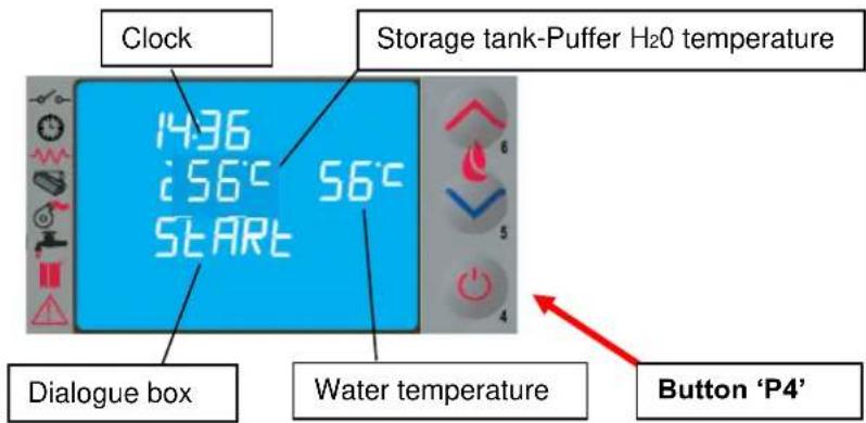
text_image
Clock Storage tank-Puffer H2O temperature 1436 i56°C 56°C START Dialogue box Water temperature Button 'P4'The stove carries out the startup stages in sequence according to the procedures defined by the parameters that manage levels and times, reaching the work condition unless anomalies or alarms occur, according to the following table:
| Status | Devices | |||
| igniter | Fume extr. | auger | exch. | |
| OFF | OFF | OFF | OFF | OFF |
| START - PREHEAT | ON | ON | OFF | OFF |
| PELLET PRELOAD | ON | ON | ON | OFF |
| AWAITING FLAME | ON | ON | OFF | OFF |
| PELLET LOADING | ON | ON | ON | OFF |
| FIRE PRESENT | OFF | ON | ON | ON |
| WORK | OFF | ON | ON | ON |
| WORK MODULATE | OFF | ON | ON | ON |
| BRAZIER CLEANING | OFF | ON | ON | ON |
| WORK | OFF | ON | ON | ON |
| FINAL CLEANING | OFF | ON | OFF | - |
After a certain time has elapsed, if the fume temperature has not reached the permissible minimum value the stove goes in alarm status.

- Do not use flammable liquids to light the unit.
- In case of persistent failed lighting, contact the Service Centre.
4.4 Work stage
After the 'STARTUP' stage, the stove goes to the 'WORK' mode which is the normal operation mode. The user can adjust the heating power from the max. value of 5 to a min. of 1 with the buttons 'P5' and 'P6'. DHW circuit function activation ON is displayed by the segment/LED [A].
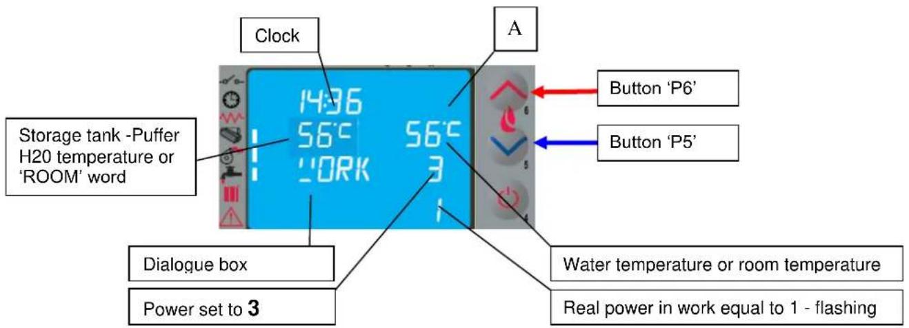
text_image
Clock Storage tank -Puffer H20 temperature or 'ROOM' word A 1436 56°C 56°C WORK A Button 'P6' Button 'P5' Dialogue box Power set to 3 Water temperature or room temperature Real power in work equal to 1 - flashing
- Make sure to check the pellet level in the hopper so that the flame does not go out due to lack of pellets.
- Make sure the unit is off when loading pellets.
- The pellet hopper lid must always remain closed; it must only be opened when loading fuel.
- The bags of pellets must be kept at least 1.5 m from the stove.
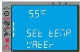
4.4.1 Modifying the water temperature setting
To modify the water temperature, press button P1 and then increase or decrease the temperature parameter with buttons P1 and P2. When the water temperature has reached the set value, the power is automatically brought to the min. value, MODULATION status. Want to change the room temperature is necessary to continue with the SET button and then increase or decrease the temperature parameter with buttons P1 and P2
When the fume temperature reaches a set max. value the message 'MODULATE F' appears on the control panel and the stove activates the flame modulation procedure without any user intervention, whereas if the temperature exceeds 285°C the alarm 'AL3 HOT FUMES' appears and the stove activates the shutdown procedure.
4.4.2 Cleaning the brazier
During normal operation in work mode, the 'BRAZIER CLEANING' mode is activated at fixed intervals for a set duration.
text_image
55°C SET bEIP ‘AtE’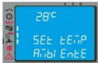
text_image
28°C SET tEIP Aibi EntE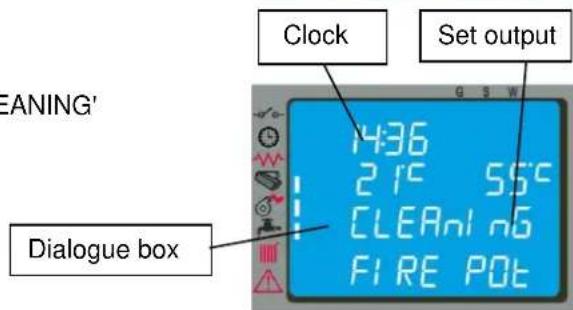
text_image
EANING' Clock Set output Dialogue box 436 215 55°C CLETLOG FIRE POT4.4.3 Water heater with heat exchanger quickly
When hot water is required, the display shows the message DHW EXCH and the LED indicated by the tap lights up. The function is carried out only if the stove is on, and the water inside the heating chamber has reached a sufficient temperature. In the remaining cases the service is not provided.
4.4.4 Water heater with storage tank
This type of installation requires the use of an external thermostat or a water probe, which measures the DHW storage tank (puffer) temperature.
In the former case, temperature SETTING is obtained by adjusting the puffer thermostat controller.
In the latter case, to modify the temperature it is necessary to press button P2 on the control panel and then increase or decrease the temperature value with buttons P1 and P2.
The DHW function is activated when the temperature falls below the SET temperature. During the STANDBY phase, the stove automatically lights and goes to WORK mode. Once the work temperature of the heating chamber water is reached, the supply of water to the storage tank (puffer) is activated. The stove display shows the message DHW and the respective LED lights up.
When the SET temperature of the storage tank is satisfied, the STOVE activates the heating system. If there is no further demand, the stove goes on STANDBY or to MODULATION, depending on the settings (see par. 4.6.2). If the stove is in OFF status, it does not light and does not provide the service.
4.4.5 System with puffer / heat storage
This type of installation requires the use of an external thermostat or a water probe, which measures the puffer water temperature.
In the former case, temperature SETTING is obtained by adjusting the puffer thermostat controller.
In the latter case, to modify the temperature it is necessary to press button P2 on the control panel and then increase or decrease the temperature value with buttons P1 and P2.
When the temperature drops below the SET external thermostat temperature:
If the stove is in the AWAITING REQUEST stage, it automatically turns on and goes to WORK status and the supply of water to the puffer is activated when the work temperature of the heating chamber water is reached. When the puffer SET temperature is met, the stove goes to AWAITING REQUEST (make sure to set the STANDBY function to ON, see par. 4.6.2).
If the stove is in OFF status, it does not turn on and does not provide the service.
It is possible to choose the temperature SETTING of the DHW storage tank and of heating from a min. of 54^ C (STD pump start value) to a max. of 80^ C with minimum return temperature not lower than (50-55)^ C in order to prevent condensation inside the chamber.
4.5 Shutting down
To shut down the stove, just press the button 'P4' for about 2 seconds.
The auger is immediately stopped and the fume extractor is brought to high speed, making the message 'FINAL CLEANING' appear on the display.
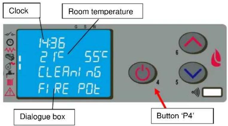
text_image
Clock Room temperature 14:36 21°C 55°C CLEAnl n6 FIRE POT Dialogue box Button 'P4'At the end of the operation the message 'OFF' appears in the dialogue box. During the shutdown stage the stove cannot be restarted until the fume temperature has fallen below a set value for a fixed time, with the message 'WAITING COOL' appearing in the dialogue box.
At the end of the operation, the message 'OFF' will appear in the dialog box.
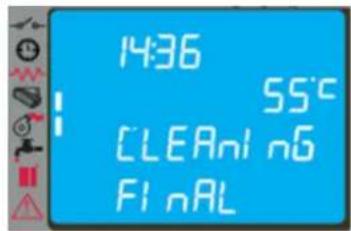
text_image
1436 55°C CLEAN/06 FINAL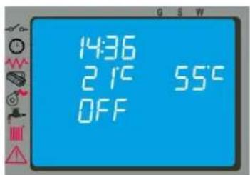
text_image
14:36 21°C 55°C OFF4.6 Menu
Press button 'P3' (SET) to access the menu; this is divided into various items and levels for accessing the settings of the electronic controller.
The following table summarises the menu structure with the selections available to the user.
| Menu Item | Position Level 2 | Menu Item | Position Level 3 | Parameter Name | Unit |
| Menu 01 | M-1-1 | Enable Chrono | M-1-1-01 | Enable Chrono | On/Off |
| M1-2 | Day Program | M-1-2-01 | Day Chrono | On/Off | |
| M-1-2-02 | Start 1 Day | ||||
| M-1-2-03 | Stop 1 Day | ||||
| M-1-2-04 | Start 2 Day | ||||
| M-1-2-05 | Stop 2 Day | ||||
| M1-3 | Weekly Program | M-1-3-01 | Week Chrono | On/Off | |
| M-1-3-02 | Start Prog-1 | ||||
| M-1-3-03 | Stop Prog-1 | ||||
| M-1-3-04 | Monday Prog-1 | ||||
| M-1-3-05 | Tuesday Prog-1 | ||||
| M-1-3-06 | Wednesday Prog-1 | ||||
| M-1-3-07 | Thursday Prog-1 | ||||
| M-1-3-08 | Friday Prog-1 | ||||
| M-1-3-09 | Saturday prog-1 | ||||
| M-1-3-10 | Sunday Prog-1 | ||||
| M-1-3-11 | Start Prog-2 | ||||
| M-1-3-12 | Stop Prog-2 | ||||
| M-1-3-13 | Monday Prog-2 | ||||
| M-1-3-14 | Tuesday Prog-2 | ||||
| M-1-3-15 | Wednesday Prog-2 | ||||
| M-1-3-16 | Thursday Prog-2 | ||||
| M-1-3-17 | Friday Prog-2 | ||||
| M-1-3-18 | Saturday prog-2 | ||||
| M-1-3-19 | Sunday Prog-2 | ||||
| M-1-3-20 | Start Prog-3 | ||||
| M-1-3-21 | Stop Prog-3 | ||||
| M-1-3-22 | Monday Prog-3 | ||||
| M-1-3-23 | Tuesday Prog-3 | ||||
| M-1-3-24 | Wednesday Prog-3 | ||||
| M-1-3-25 | Thursday Prog-3 | ||||
| M-1-3-26 | Friday Prog-3 | ||||
| M-1-3-27 | Saturday prog-3 | ||||
| M-1-3-28 | Sunday Prog-3 | ||||
| M-1-3-29 | Start Prog-4 | ||||
| M-1-3-30 | Stop Prog-4 | ||||
| M-1-3-31 | Monday Prog-4 | ||||
| M-1-3-32 | Tuesday Prog-4 | ||||
| M-1-3-33 | Wednesday Prog-4 | ||||
| M-1-3-34 | Thursday Prog-4 | ||||
| M-1-3-35 | Friday Prog-4 | ||||
| M-1-3-36 | Saturday Prog-4 | ||||
| M-1-3-37 | Sunday Prog-4 | ||||
| M1-4 | Week-End Program | M-4-2-01 | Week-End Chrono | ON/OFF | |
| M-4-2-02 | Start 1 Week-End | ||||
| M-4-2-03 | Stop 1 Week-End | ||||
| M-4-2-04 | Start 2 Week-End | ||||
| M-4-2-05 | Stop 2 Week-End | ||||
| Menu 02User adjustments | M-2-1 | Set Clock | |||
| M-2-2 | Standby mode | On/Off | |||
| M 2-3 | Initial load | On | |||
| M 2-4 | Pellet type | Pellet adjustment | (-9 - +9) | ||
| M 2-5 | Initial load auger 2 | On | |||
| Menu 03User settings | M-3-1 | Language | -- | ||
| M-3-3 | Buzzer mode | On/Off | |||
| M-3-4 | Lighting | (0 - 100) | |||
| M-3-6 | Heating Delta | (0.5 - 20) | |||
| M-3-7 | Storage tank-Puffer Delta | (0.5 - 20) | |||
| M-3-8 | Pellet level | On/Off | |||
| M-3-9 | DHW control | ON/OFF/EST | |||
| Menu 04Boiler status | menu for technician | ||||
| Menu 05technician settings | menu for technician | ||||
| Menu 06Installer settings | menu for technician | ||||
4.6.1 Menu 01 – Chrono setting
Allows all chronothermostat functions to be enabled/disabled; select ON to activate the function and display the relevant segment/LED [D]
When Daily, Weekly or Week End programming is entered, the appropriate segment/LED [ C ] appears in the top right of the display.
Regarding selections and entering times,
use the buttons according to the table in par. 4.2.
By accessing the submenu: DAY PROGRAM, the daily chronothermostat functions can be enabled/disabled and set. It is possible to set two operation stages delimited by the times set according to the following table where the setting OFF tells the clock to ignore the command.
| Selection | Meaning | Possible Values |
| START1 | activation time | time - OFF |
| STOP1 | deactivation time | time - OFF |
| START2 | activation time | time - OFF |
| STOP2 | deactivation time | time - OFF |
By accessing the submenu: WEEK PROGRAM it is possible to enable/disable and set the weekly chronothermostat functions.
The weekly programmer has 4 independent programs whose final effect consists of a combination of the
4 programmings.
The weekly programmer can be activated or deactivated; also, by setting OFF in the time field, the clock ignores the corresponding command.

Carry out programming making sure not to overlap the hours of activation and/or deactivation on the same day in different programs.
By accessing the submenu: WEEK-END PROGRAM it is possible to enable/disable and set the week-end (Saturday - Sunday) chronothermostat functions.

Activate WEEK-END programming only after deactivating the weekly programming.
To avoid unwanted startup and shutdown operations, only activate one program at a time.
Deactivate the daily program if the weekly program is required; with this setting it is advisable to deactivate the week-end program.
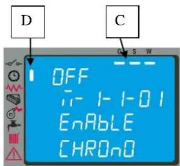
text_image
D OFF i- 1-1-0 1 Enable CHRONO C S W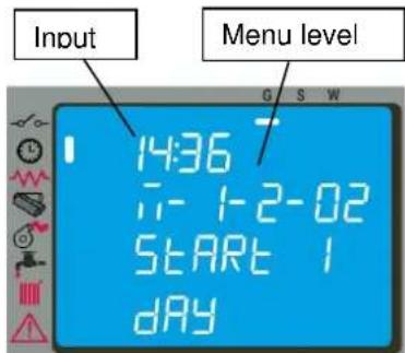
text_image
Input Menu level 14:36 1- 1-2-02 START 1 DAY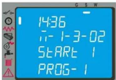
text_image
14:36 1- 1-3-02 START 1 PROG-1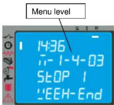
text_image
Menu level 14:36 -1-1-4-03 STOP 1 "EEH-End4.6.2 Menu 02 - User adjustments
With this menu it is possible to do a number of settings as follows
- Set clock
Before operating with the stove, it is necessary to set the current time and date so that there is a reference for possible chrono programming. The electronic controller has a lithium battery, model CR2032 3 Volt, giving the internal clock an autonomy of more than 4-5 years; with the stove off, whenever the clock does not keep the time, or a series of zeros is displayed at restart, the battery must be replaced by calling an authorised service centre.
- Standby mode
On activating this function, the stove shuts down automatically after the water temperature has remained above the SET value (Tset + T ) for a given time.
The next automatic relighting will be possible only when the temperature falls below the SET temperature by a given value entered in the parameters table (Tset - T ) where T default = 2°C.
Manual commands from the control panel have priority over programming.
With the selection OFF the stove does not activate the STANDBY mode and functions normally activating the MODULATION function when the temperature exceeds the SET value.
- Initial load
Setting this function allows activation of gearmotor operation, with the stove off or cold, for pellet preloading of 90 sec. It starts with button P1 and stops with button P4.
- Pellet type
With the function on, press the buttons P1 or P2 to increase or reduce pellet loading to optimise consumption and combustion, depending on the type of pellets used.
4.6.3 Menu 03 - User setting
With this menu it is possible to carry out the following settings:
- Language
With this selection it is possible to select the dialogue language from those available entered in the menu, and namely: ITALIAN - FRENCH - ENGLISH - GERMAN - SPANISH
- Buzzer
With this selection it is possible to activate/deactivate stove acoustic signalling.
- Lighting
With this selection it is possible to change the brightness of the backlit display from a minimum of 0 to a maximum of 100.
- Heating Delta
With this selection, it is possible to set:
- the range between the SET temperature and the actual stove shutdown temperature;
- the range between the SET temperature and the actual stove relighting temperature.
This range can be set from a min. of 0.5^ C to a max. of 20^ C depending on the customer's needs and/or the type of system.
- Boiler/Puffer Delta
With this selection, it is possible to set:
the range between the SET temperature and the actual stove relighting temperature.
This range goes from a min. of 0.5^ C to a max. of 20^ C depending on the customer's needs and/or the type of system.
- DHW control
The selection ON allows to manage DHW from the storage tank or heat exchanger through the signal from the thermostat or flow switch.
The selection EST allows domestic hot water to be controlled in the summer (with heating off), via the signal from thermostat or probe. Selecting this item enables operation of just the DHW branch; standby is forced to ON and post-circulation follows that set in the menu M-6-9.
The summer function can be displayed only if the menu M-6-8 is set to T-PUFFER or S-PUFFER.
4.6.4 Menu 04 – stove status
With this selection it is possible to display the instantaneous stove status giving the operating status of the various devices connected to it; various pages placed in succession are available for monitoring.
4.6.5 Menu 05 – settings by technician
This selection is reserved for the authorised technician of the COLA service centre.

Modification of the technical parameters of menu 09 must be done by authorised and competent personnel; any changes made at random can cause serious damage for which COLA declines any liability.
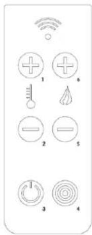
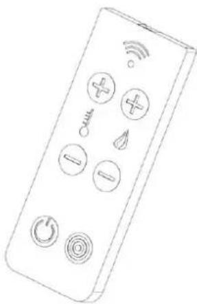
4.7 Remote control
The remote control works with the settings made in the control panel and allows stove lighting-shutdown, and adjustment of the required output and temperature.
Since this device transmits through an infrared diode, it must be pointed at the receiver unit in the control panel.
The remote control allows the following operations:
text_image
Diagram of a remote control panel with labeled icons for signal, temperature, and function buttonsButton P3: Stove lighting-shutdown
Button P1: Increase room temperature
Button P6: Increase output level
Button P5: Decrease output level
Button P2: Decrease room temperature
Button P4: Jolly
natural_image
Line drawing of a remote control device with icons for signal, Wi-Fi, temperature, and function buttons (no text or labels)4.7.1 Replacing the battery
The remote control (model with 6 button) is powered by a 3-volt CR2025 type battery (included) located in the bottom of the device. Also remove the insulation before use. For its insertion and possible replacement, proceed as follows:
- Operate the lever indicated;
- Pull out the battery tray and replace the battery (3-volt CR2025 model) respecting the polarity;
- Insert the tray;
- Check proper functioning.
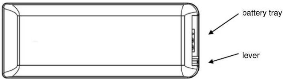
text_image
battery tray lever
- Keep the remote control away from direct heat sources and water.
- The remote control battery must be replaced and disposed of safely in compliance with local regulations;
4.8 Thermostat - external chronothermostat
The unit controls the room temperature by means of its own digital thermostat whose function is to detect the temperature through a probe and lower the heat output when the set temperature is reached.
To use an external thermostat, contact an authorised technician and proceed as follows:
- turn off the power by means of the main switch on the back and detach the power cable;
- remove the side panel to access the electronic controller;
- referring to the wiring diagram, connect the two wires of thermostat to the respective board TERM terminals;
- refit everything and check correct operation.
The setting procedure is as follows:
- external thermostat: SET the temperature to 7°C;
- external chronothermostat: SET the temperature to 7°C and disable the chrono functions from the menu 03-01.
All the menu functions do not change for each of the settings and signalling of the connection occurs with lighting up of the segment LED on the status bar of the display.
text_image
Diagram showing various industrial or safety symbols with arrows pointing to a black rectangle and a warning symbol.4.9 Idle period (end of season)
If the stove is not used for long periods, or at the end of each season, it is advisable to proceed as follows:
- remove all the pellets from the hopper;
- disconnect the power supply;
- clean thoroughly and, if necessary, have any damaged parts replaced by qualified personnel;
- protect the stove from dust with suitable covering;
- store in a dry and safe place protected from atmospheric agents.
5 STOVE CLEANING
Stove cleaning is very important to prevent: blackening of the glass, poor combustion, deposits of ash and unburnt products in the brazier, reduced thermal efficiency.
The stove must only operate with the fire door closed.
The fire door seals must be checked periodically to prevent any air from entering; the combustion chamber and pellet duct work in a negative pressure and the fume exhaust in a positive pressure.
Routine cleaning is normally carried out by the customer following the instructions in the manual, whereas extraordinary maintenance, at least once a year, must be performed by the authorised Service Centre.

- Cleaning operations for all parts must be carried out with the stove unplugged and cold;
- Dispose of cleaning waste in accordance with the current local regulations;
- The stove must not be operated without its cladding;
- Avoid the creation of smoke and unburnt products during lighting and/or normal operation.
Given below are the control and/or maintenance operations for correct stove use and operation.
| Parts / PeriodType of cleaning | 1 dayroutinecleaning | 2-3 daysroutinecleaning | 1 monthroutinecleaning | 2-3 monthsroutinecleaning | 1 yearextraordinarycleaning: carried outby the Service Centre |
| Brazier | ■ | ||||
| Ash compartment-pan | ■ | ||||
| Door glass | ■ | ||||
| Heating chamber tube bundle | ■ | ■ | |||
| Manifold – fume extractor | ■ | ■ | |||
| Glass - door seal | ■ | ||||
| Pipe - flue connection | ■ |
5.1 Cleaning the brazier
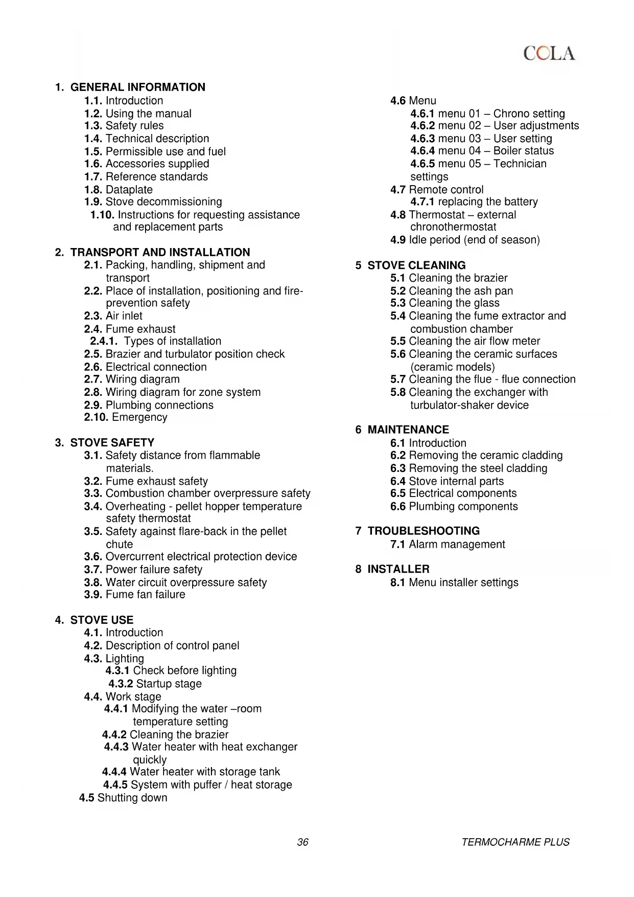
Remove the brazier and the ash deposited in the combustion chamber and brazier holder. A suitable vacuum cleaner may be used for this purpose. This operation must be carried out daily, especially in case of accumulated unburnt matter, to ensure perfect combustion conditions, since the brazier holes allow the flow of combustion air.
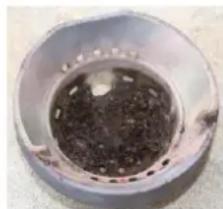
natural_image
Close-up of a metallic cylindrical container filled with dark granular material, no visible text or symbols.Brazier dirty

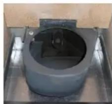
natural_image
Close-up of a perforated metal bowl with a circular vent (no text or symbols visible)Brazier clean
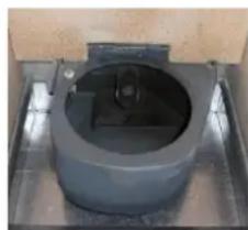
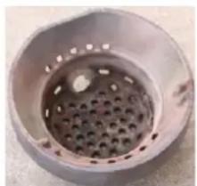
natural_image
Close-up of a dark cylindrical object with a central square opening, placed on a metal tray (no visible text or symbols)Brazier Holder clean

The brazier must rest on the brazier holder and precisely on the entire ring band without air gaps.
5.2 Cleaning the ash pan
The ash container is located directly under the brazier - brazier holder. To clean it, open the fire door and remove the ash and any combustion residuals using a suitable vacuum cleaner.
Close the door after cleaning. The ash container can be cleaned every 2-3 days depending on stove use.
5.3 Cleaning the glass
The glass can be cleaned using a damp cloth and specific non-abrasive detergents.
Special slots between the glass, glass stops and fire door at the top and bottom allow air to circulate on the inside surface of the glass. These slots must be kept clean of any deposits of ash and dust. Therefore periodically clean all around the glass, on the inside and outside of the door.
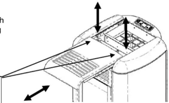
5.4 Cleaning the fume extractor and combustion chamber
The combustion chamber must be cleaned at least once a year, removing all combustion residuals from the internal fume pipes and flueways. To carry out this operation, it is necessary to remove the stove top cover, and the heating chamber cover, undoing the fixing screws, then clean the turbulators and internal fume pipes.
Also make sure to clean the fume extractor located under the chamber, accessed by removing the front door down the chamber.
Every 3-4 months clean the inside walls of the combustion chamber using suitable equipment (brushes) and replace the vermiculite wall if necessary.
Every 1800 hours of operation or 2000 Kg pellet, by means of a message 'SERVICE DUE', the stove signals the need for extraordinary maintenance (not under warranty) to be performed by qualified personnel who will carry out complete cleaning and reset the message.

Any knocking or forcing can damage the fume extractor, making it noisy during operation; therefore it is advisable to have this operation carried out by qualified personnel.
5.5 Cleaning the air flow meter
The air flow meter (it measures the flow of combustion air) installed inside the inlet pipe requires periodical internal cleaning every 3-4 months, using suitable equipment (blowing compressed air or suitable brushes).
5.6 Cleaning the ceramic surfaces (ceramic models)
The ceramic tiles are handicraft products and therefore may have minor surface imperfections such as tiny spots or slight colour differences. It is advisable to use a soft dry cloth to clean the ceramic surfaces; the use of detergents could highlight any flaws.
5.7 Cleaning the flue - flue connection
The flue connection must be cleaned at least once a year or whenever necessary.
Cleaning requires the suction and removal of the residuals in all the vertical and horizontal sections as well as the bends from the stove to the flue.
It is advisable to also clean the flue every year, to ensure correct and safe evacuation of fumes.
5.8 Cleaning the exchangers with turbulator-shaker device
The fume ducts inside the heating chamber must be cleaned at least once a day by operating the two knobs repeatedly with an upward and downward movement after opening the sliding cover.

Carry out this operation with the stove off and cold.
RH - LH control knobs of the turbulator-shaker device in heating stove operation low position.
natural_image
Technical line drawing of a mechanical device with directional arrows indicating assembly or movement (no text or symbols present)6 MAINTENANCE
6.1 Introduction
Operations on the internal parts of the stove must be carried out by qualified personnel. Contact the nearest authorised service centre.

Make sure the stove is unplugged and cold before carrying out any work on it.
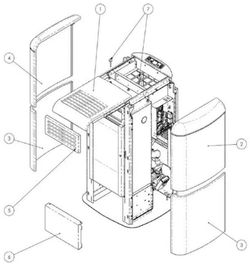
6.2 Removing the cladding
Key:
1 - Top cover ceramic
2 - Tile upper right side
3 - Tile lower lateral right-left
4 - Tile upper left side
5 - Top front panel ceramic
6 - Bottom front panel steel
7 - Extensions with knob for turbulators
text_image
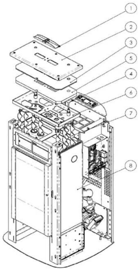
Technical diagram of a refrigerator internal structure with numbered components for identification6.3 Stove internal parts
Key:
1 - Safety valve
2 - Heating chamber cover
3 - Isolcart protection
4 - Knob for shaking turbulators
5 - Vermiculite protection
6 - Cover bottom frame
7 - Turbulators
8 - Heating chamber
text_image
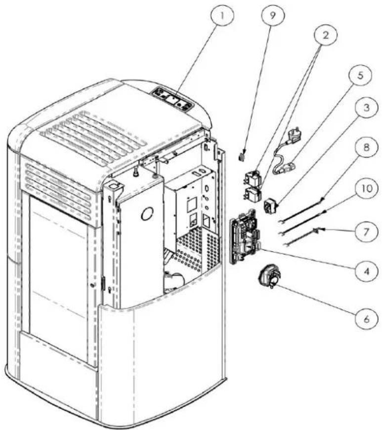
Exploded view diagram of an electronic device with numbered components for identification6.4 Electrical components
Key:
1 - Control panel model F047
2 - Safety thermostat
3 - ON-OFF switch with fuses
4 - Electronic board
5 - Power cable
6 - Vacuum switch
7 - Fume probe
8 - Room probe
9 - Serial connection
10-Water probe
text_image
Technical diagram of a server rack with numbered components for identification6.5 Plumbing components
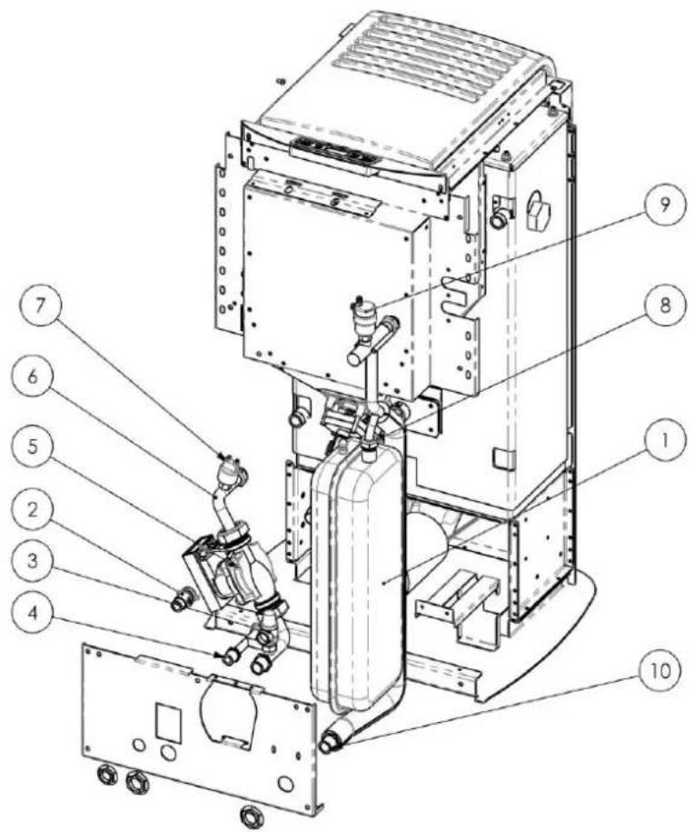
text_image
Technical diagram of an industrial equipment assembly with numbered components for identificationKey:
1- Membrane expansion tank
2- System drain cock
3- Safety valve
4- System filling connection
5- Heating circulating pump
6- Heating chamber - pump return
7- Pressure transducer
8- Expansion tank connection
9- Air venting valve
10- Delivery pipe
7 TROUBLESHOOTING
7.1 Alarm management
Alarms are indicated by an acoustic signal (if activated) and a message on the control panel.
In case of an alarm, shut down the stove, eliminate the cause and restart the stove according to the normal procedure described in this manual.
Every alarm status causes immediate stove shutdown.
The alarms, with causes and cures, which can appear on the control panel are listed below:
| ALARMS - MESSAGES | |||
| Signalling | Fault | Possible causes | Cures |
| AL 1 POWER FAILURE | -The stove does not start. | -No power during the lighting stage. | -Turn the stove OFF by pressing the button P4 and repeat the lighting procedure.-Other reinstatement operations must be carried out by a service centre. |
| AL 2 FUME PROBE | -Occurs in case of a fume temperature probe fault.-The shutdown procedure is activated. | -Faulty probe-The probe is disconnected from the board. | -Reinstatement operations must be carried out by a service centre. |
| AL 3 HOT FUMES | -Occurs if the fume probe detects a fume temperature above 280°C.-The shutdown procedure is activated. | -Faulty tangential fan.-No power to tangential fan.-Too many pellets. | -Adjust the pellet flow.-Other reinstatement operations must be carried out by a service centre. |
| AL 4 FAN FAIL | -Occurs when the exhaust fan is faulty.-The shutdown procedure is activated. | -The fume fan is blocked.-Faulty speed control sensor.-No power to fume fan. | -Reinstatement operations must be carried out by a service centre. |
| AL 5 NO IGNITION | -No flame in ignition stage.-The shutdown procedure is activated. | -The pellet hopper is empty.-The electrical element is faulty, dirty or not correctly positioned.-Pellet load setting incorrect. | -Check pellets in hopper.-Check the lighting procedures.-Other reinstatement operations must be carried out by a service centre. |
| AL 6 NO PELLETS | -Brazier not fed with pellets. | -The pellet hopper is empty.-The pellet feed gearmotor has to adjust.-The gearmotor does not feed pellets. | -Check pellets in hopper.-Adjust the pellet flow-Other reinstatement operations must be carried out by a service centre. |
| AL 7 THERMAL SAFSignalling | -Occurs in case of cutting in of auger duct temperature or heating chamber water temperature safety thermostat.-The system is stopped.Fault | -The safety thermostat has detected a temperature above the setting threshold due to overheating of the bottom part of the hopper or the heating chamber water, blocking gearmotor operation.Possible causes | -Check the cause of excessive overheating.-Reset the relevant safety thermostat by pressing the reset button.Cures |
| AL 8NO NEG PRESS | -In the work stage the stove detects a pressure below the vacuum switch setting threshold.-The system is stopped. | -The combustion chamber is dirty.-The fume duct is obstructed.-The fire door is not closed.-The overpressure valves are open-stuck.-Faulty vacuum switch. | -Check cleanness of the fume duct and combustion chamber.-Check hermetic closing of the door.-Check closing of the overpressure valves.-Other reinstatement operations must be carried out by a service centre. |
| AL 9INSUFF DRAUGHT | -Appears when the combustion air flow is below a certain threshold. | -The combustion chamber is dirty.-The fume duct is obstructed.-The fire door is not closed.-The overpressure valves are open-stuck.-Faulty air flow meter. | -Check cleanness of the fume duct and combustion chamber.-Check hermetic closing of the door.-Check closing of the overpressure valves.-Other reinstatement operations must be carried out by a service centre. |
| AL E WATER PRESSURE | -Occurs when the water pressure does not come within the values for correct operation.-The system is stopped. | -Occurs when the pressure transducer on the water circuit detects a pressure below 0,6 bar or above the fixed limits. | -Check the cause of the problem, restoring the circuit pressure by bringing it to the normal operating value. |
| AL b AUG TRIAC ERROR | -Occurs when the gearmotor works continuously and for more than 60 sec.-The system is stopped. | -The controller detects a faulty gearmotor control relay (contacts stuck). | -Reinstatement operations must be carried out by a service centre. |
| AL c WATER PROBE | -Occurs in case of a water temperature probe fault.-The shutdown procedure is activated. | -Faulty probe-The probe is disconnected from the board. | -Reinstatement operations must be carried out by a service centre. |
| AL d HOT WATER | -Occurs when the water temperature has exceeded the fixed limits.-The system is stopped. | -Occurs when the temperature probe in the heating chamber detects a value above 92°C. | -Check the cause of the problem, restoring the temperature by bringing it to the normal operating value. |
| WAITING COOL | -Occurs on relighting the stove immediately after having shut it down. | -Reset attempt in shutdown stage with stove hot in cooling stage. | -Alarm reset is possible only after shutdown. |
| AIR FLOW METER FAILURE | -Occurs when the air flow meter is disconnected. | -The controller does not detect the quantity of combustion air and does not shut down the stove; it only excludes the air flow meter functions. | -Reinstatement operations must be carried out by a service centre. |
| FROST RISK | -Occurs when the water temperature falls below a certain value. | -The stove control detects the water temperature below 6°C and displays a message. | -The pump starts in order to move the water inside the heating circuit.- Monitor the water temperature so that it does not fall below 0°C. |
| SERVICE DUE | Occurs when the stove has exceeded 1800 hours of operation or 2000 Kg pellet, since the previous servicing. | -Extraordinary maintenance notice. | -Cleaning - extraordinary maintenance and reinstatement operations must be carried out by a service centre. |
The Manufacturer reserves the right to make technical or aesthetic changes to the products at any time without notice.
The drawings, measurements, diagrams and any other configurations are given only by way of example.
8 INSTALLER
8.1 Menu installer settings
The following instructions are intended only for technical personnel specialised in heating units manufactured by COLA.

Changing the parameters in a non-appropriate way can cause serious damage to people, the units and the environment. In this case, Cola s.r.l. declines any liability.
To access the INSTALLER SETTINGS menu, press button P3 - MENU and use the scroll buttons to display the item INSTALLER SETTINGS and then press button P3 - MENU. Use the scroll buttons to display access key 10 and press button P3 - MENU.again.
The various parameters can be displayed with the scroll buttons; access with button P3 - MENU, edit them with the scroll buttons and exit with ESC.
It contains the adjustment parameters given below.
| Parameter code | Default | Description |
| M-6-1 | 0 | For increasing or decreasing auger OFF duration for all powers. |
| M-6-2 | 0 | For increasing or decreasing fume extractor speed for all powers, by a value of 5% for each unit. |
| M-6-3 | OFF | Enable key lock. |
| M-6-4 | 2°C | Adjustment probe temperature setting ON/OFF delta (see parameter M-6-7) |
| M-6-5 | 2 min. | Stove shutdown delay. Valid only in case of Standby set to ON. |
| M-6-6 | OFF | For enabling self-calibration. |
| M-6-7 | S-AMB... | Allows the choice of sensor for setting stove adjustment (heating branch)O045: Remote graphic display with incorporated room sensorT-AMBIEN: 'normally open' type external room thermostatT-PUFFER: 'normally open' type external thermostat on the hot water storage tank (puffer)S-ACQUA (S2): External probe on the delivery (default) or puffer and connected to the main boardS-AMBI: Ambient probe on stove, connected to the mainboard |
| M-6-8 | OFF | Allows the choice of sensor for setting stove adjustment (DHW branch)OFF: DHW control deactivatedFLUSSOST: Flow switch on the DHW line of the rapid heat exchanger and connected to the main board (active only with stove on in work phase)T-BOILER: 'Normally open' type external thermostat on the hot water storage tank (puffer) (SUMMER control activatable by the user)S-BOILER (S3): External probe on the hot water storage tank (puffer) and connected to the main board. (SUMMER control activatable by the user) |
| M-6-9 | HEATING | Allows setting of post-circulation (dissipation of residual heat in the stove) in summer modeRISC: heating branchSANI: DHW branch |
| M-6-A | OFF | Enables or disables the additional tank |
| M-6-B | OFF | Enables or disables activation of the external stove when the pellet-fired stove goes in alarm status |
1 RECOMMANDATIONS GÉNÉRALES
1.4 Description technique
natural_image
Technical line drawing of a mechanical device with an arrow indicating leftward motion and a warning symbol (no text or labels)1.7 Normes de reference
natural_image
Close-up of a door with a black arrow pointing to the left side of the door (no visible text or symbols)text_image
Vertical toolbar with icons representing various industrial or safety symbols including tools, clocks, wavy lines, pipes, and warning symbols.Contact externe
Chrono
text_image
14:36 π-1-3-02 START 1 PROG-1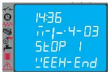
text_image
14:36 11-1-4-03 STOP 1 'EEH-End- Delta Boiler/Puffer
text_image
Diagram of a remote control panel with labeled function icons including Wi-Fi, thermal, and power symbolsTouche P3: Allumage-extinction du poêle
natural_image
Line drawing of a remote control device with buttons and sensors (no text or symbols)text_image
Diagram showing various industrial or safety symbols with arrows pointing to specific features like clocks, wavy lines, and warning signs.natural_image
Close-up of a cylindrical container filled with dark granular material, possibly a container or mold (no visible text or symbols)Brasier encrassé
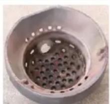
natural_image
Close-up of a metallic circular component with a perforated interior (no text or symbols visible)Brasier propre
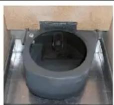
natural_image
Close-up of a cylindrical mechanical component with a central housing and mounting base (no visible text or symbols)Support de brasier

natural_image
Technical line drawing of a mechanical device with arrows indicating assembly or force direction (no text or symbols)6 ENTRETIEN
6.1 Introduction
text_image
Technical diagram of a device interior with numbered components for identificationtext_image
Exploded view diagram of an electronic device with numbered components for identificationtext_image
Technical diagram of a computer case with numbered components for identification6.5 Composants hydrauliques
Légende :
text_image
Technical diagram of an industrial machine with numbered components for identificationLégende :
natural_image
Technical line drawing of a mechanical device with an arrow indicating leftward motion and a warning symbol (no text or labels)1.7 Bezugsnormen
natural_image
Exterior view of a door with a black arrow pointing to the door panel (no text or symbols visible)text_image
Collection of safety and warning symbols including clock, gear, faucet, warning sign, and warning triangleExterner Kontakt
Uhrenthermostat
Heizwiderstand
Förderschnecke
Saugzuggebläse
- Delta Boiler/Puffer
text_image
Diagram of a remote control panel with labeled icons including Wi-Fi, plus signs, thermometer, and power buttonnatural_image
Line drawing of a remote control device with icons for signal, power, and function buttons (no text or labels)text_image
Diagram showing various safety symbols and warning labels, including clocks, wavy lines, pipes, water tanks, and warning signs.natural_image
Close-up of a circular metallic object with a dark central component and small protrusions, possibly a container or sensor (no visible text or symbols)natural_image
Close-up of a circular metal grate with perforated interior (no text or symbols visible)Brenntopf sauber
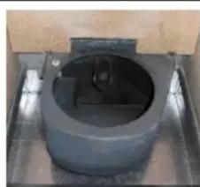
natural_image
Close-up of a cylindrical mechanical component with a central square opening, mounted on a metal base (no visible text or symbols)text_image
Technical diagram of a device with labeled components and directional arrows indicating assembly or flow.6 WARTUNG
6.1 Vorwort
text_image
Technical diagram of an internal device with numbered components for identification6.3 Innere Ofenkomponenten
Zeichenerklärung:
text_image
Exploded view diagram of a server rack with numbered components for identificationtext_image
Technical diagram of a computer tower case with numbered components for identificationZeichenerklärung:
text_image
Technical diagram of an industrial machine with numbered components for identification7 FEHLERSUCHE
text_image
Technical diagram of a refrigerator with labeled parts H, I, and M indicating front panel, side panel, and interior ventilation system.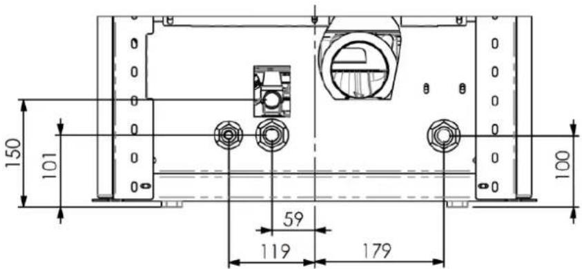
text_image
150 101 59 119 179 100DETALLE Z ESCALA 1:7,5
natural_image
Technical line drawing of a mechanical device with an arrow indicating leftward motion and a warning symbol (no text or labels)natural_image
Exterior view of a door with a black arrow pointing to the door panel (no text or symbols visible)text_image
SS°C SET TETP AGUA 20°C SET TETP Aibi EntEtext_image
14:36 7-1-4-03 STOP 1 FIN SETTAtext_image
Diagram showing various electrical and thermal symbols on a device, including Wi-Fi, plus signs, thermometer, flame, power, and control icons.natural_image
Line drawing of a remote control device with buttons and sensors (no text or symbols)text_image
Diagram showing various warning symbols and an arrow pointing to a vertical bar with warning labels like clock, wrench, and water drop.natural_image
Close-up of a circular container filled with dark granular substance, no visible text or symbolsBrasero sucio
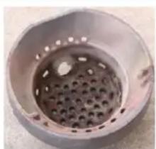
natural_image
Close-up of a perforated metal grate or drain component (no text or symbols visible)Brasero limpio
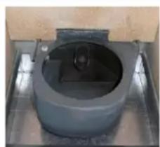
natural_image
Close-up of a cylindrical mechanical component with a central square opening, mounted on a metal frame (no visible text or symbols)Portabrasero limpio