
PA240 - Receiver ARCAM - Free user manual and instructions
Find the device manual for free PA240 ARCAM in PDF.
User questions about PA240 ARCAM
0 question about this device. Answer the ones you know or ask your own.
Ask a new question about this device
Download the instructions for your Receiver in PDF format for free! Find your manual PA240 - ARCAM and take your electronic device back in hand. On this page are published all the documents necessary for the use of your device. PA240 by ARCAM.
USER MANUAL PA240 ARCAM
PA720 / PA240 / PA410
Safety Guidelines
Important Safety Instructions
- Read these instructions.
- Keep these instructions.
- Heed all warnings.
- Follow all instructions.
- Do not use this apparatus near water.
- Clean only with dry cloth
- Do not block any ventilation openings. Install in accordance with the manufacturer's instructions.
- Do not install near any heat sources such as radiators, heat registers, swirves, or other apparatus (including amplifiers) that produce heat.
- Do not defeat the safety purpose of the polarized or grounding type plug.
A polarized plug has two blades with one wider than the other. A grounding type plug has two blades and a third grounding prong. The wide blade or the third prong are provided for your safety. If the provided plug does not fit into your outlet, consult an electrician for replacement of the obsolete outlets.
- Project the power cord from being walled on or pinched particularly at plugs, convenience receptacles, and the point where they exit from the apparatus.
- Only use attachments/accessories specified by the manufacturer.
- Use only with the cart, stano, tripod bracker, or variable specified by the manufacturer, or sold with the apparatus.
When a cart is used, use caution when moving the cart/aparatus combination to avoid injury from topover.

-
Uniloc this apparatus during lightning storms or when unused for long periods of time.
-
Referral servicing to qualified service personnel
Servicing is required when the apparatus has been damaged in any way, such as power-supply cord or plug is damaged, liquid has been spilled or objects have fallen into the apparatus; the apparatus has been exposed to rain or moisture, does not operate normally, or has been dropped.
- Object or liquid entry
WARNING - Take care that objects do not fill and liquids are not spilled into the enclosure through any openings. The equipment shall not be exposed to dripping or splashing. Liquid filled objects such as vases should not be placed on the equipment.
- Climate
The equipment has been designed for use in moderate climates and in domestic situations.
17.Cleaning
Unplug the unit from the mains supply before clearing.
The case should normally only require a twice with a soft, lint-free cloth. Do not use chemical solvents for cleaning.
We do not advise the use of furniture cleaning sprays or polishes as they can cause permanent white marks.
18.Power sources
Only correct the equipment in a power supply of the type described in the operating instructions or as marked on the equipment.
The primary method of isolating the equipment from the mains supply is to remove the mains plug. The equipment must be installed in a manner that makes disconnection possible.
- Abnormal smell
If an abnormal smell or smoke is detected from the equipment, turn the power off immediately and unplig the equipment from the wall out of Contact, your dealer and do not reconnect the equipment.
- Damage requiring service
The equipment should be serviced by qualified service personnel when:
A. The power-supply cord or the plug has been damaged, or
3. Objects have fallen, or liquid has spilled into the equipment, or
C. the equipment has been exposed to rain, or
12. The equipment does not appear to operate normally or exhibits a marked change in performance, or
The equipment has been dropped or the enclosure damaged.


CAUTION To reduce the risk of electric shock, do not remove cover (for back). No user serviceable parts inside. Refer servicing to qualified service personnel.
WARNING To reduce the risk of fire or electric shock, do not expose this apparatus to rain or moisture.
The lightning flash with an arrowhead symbol within an equilateral triangle, is intended to alert the user to the presence of uninsulated dangerous voltage within the product's enclosure that may be of sufficient magnitude to constitute a risk of electric shock to persons.
The exclamation point within an equilateral triangle is intended to alert the user to the presence of important operating and maintenance (servicing) instructions in the literature accompanying the product.
CAUTION In Canada and the USA, to prevent electric shock, match the wide biase of the plug to the wide slot in the socket and insert the plug fully into the socket.
Class II product
This equipment is a Class II or double insulated electrical appliance. It has been designed in such a way that it does not require a safety connection to electrical earth ("ground") in the U.S.
Warning
Mains drug/appliance coupler is used to disconnect device and it snail remain readily operable.
Safety Compliance
Tn's equipment has been designed to meet the IEC/EN 62369-1 international electrical safety standards.
This device composes with Part 15 of the FCC Rules. Operation is subject to the following two conditions:
- This device may not cause harmful interference, and
- This device must accept any interference received, including interference that may cause undesired operation.
The building installation shall be regarded as providing protection in accordance with the rating of the wall socket outlet.
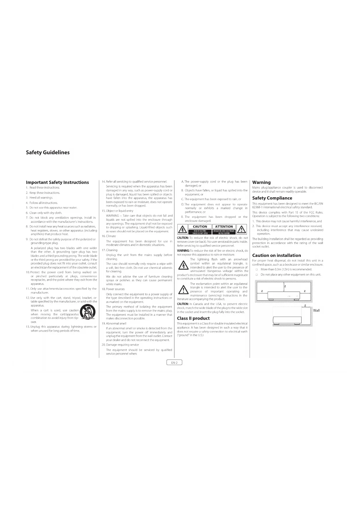
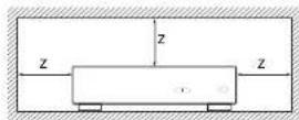
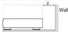
Caution on installation
or proper heat dispersal, do not install this unit in a confined space, such as a bookcase or similar enclosure.
More than 0.3m (12m) is recommended.
Do not place any other equipment on this unit.
FCC Information(for US customers)
PRODUCT
This product complies with Part 15 of the FCC Rules. Operation is subject to the following two conditions:
1. This device may not cause harmful interference, and
2. This device must accept any interference received.
including interference that may cause undesired
IMPORTANT NOTICE DONOTMODIFY THIS PRODUCT
This product, when installed as indicated in the instructions consisted in this manual, meets FCC requirements. Modification not expressly approved by ARCHAM may void your authority, granted by the FCC to use the product.
NOTE
This product has been tested and found to comply with the limits for a Class B digital device, pursuant to Part 15 of the FCC Rules. These limits are designed to provide reasonable protection against harmful interference in a residential installation.
This product generates, uses and can radiate radio frequency energy and, if not installed and used in accordance with the instructions, may cause harmful interference to radio communications. However, there is no guarantee that interference will not occur in a particular installation. If this product does cause harmful interference to radio or television reception, which can be determined by turning the product CO + and ON, the user is encouraged to try to correct the interference by one or more of the following measures:
Reorient or relocate the receiving antenna.
□ Increase the separation between the equipment and receiver.
- Connect the product into an outlet on a circuit different from that to which the receiver is connected.
Consult the local retailer authorized to distribute this type of product or an experienced radio/TV technician for help
Safety Information (for European customers)
- Avoid high temperatures. Allow for sufficient heat dispersion when installed in a racc
- Handle the power cord carefully. Hold the plug with unplugging the cord.
- Keep the unit free from moisture, water, and dust.
- Up to the power cord when not using the unit long periods of time.
Do not obstruct the ventilation holes.
Do not let foreign objects into the unit
Do not let insecticides, benzene, and thinner come contact with the unit.
Never disassemble or modify the unit in any way.
Ventilation should not be impeded by covering ventilation openings with items, such as newspapers, tablecloths or curtains.
- Naked #ame sources such as lighted canoles sho not be placed on the unit.
1. Observe and follow local regulations regarding battery disposal.
□ Do not expose the unit to dripping or splashing fluids.
- Do not place objects filled with liquids, such as vases on the unit.
Do not handle the mains cord with wet hands.
□ When the switch is in the OFF position, the equipme is not completely switched off from MAINS.
The equipment shall be installed near the power supply so that the power supply is easily accessible.
A note about recycling
This product's packaging materials are recyclable and can be reused. Please dispose of any materials in accordance with the local recycling regulations.
When discarding the unit, comply with local rules or regulations.
oalertions should never be thrown away or incinerated. bu disposed of in accordance with the local regulations concerning battery disposal.
To's product and the supplied accessories, excluding the batteries, constitute the applicable product according to the WPH directive.
Correct disposal of this product
These markings indicate that this product should not be disposed with other household waste throughout the


Pb
To prevent possible harm to the environment or human health from uncontrolled waste disposal and to conserve material resources, this product should be recycled responsibly.
To dispose of your product, please use your local return and collection systems or contact the retailer where the product was purchased.
Welcome
Thank you and congratulations...
for purchasing your Arcam PA720, PA740 or PA10 power amplifier.
Arcam has been producing specialist audio products of remarkable quality for over four decades and the new PA720, PA240 and FA410 power amplifiers are the latest in a long line of award-winning HiFi. The design of the IDA range draws upon all of Arcam's experience as one of the UK's most respected audio companies, to produce Arcam's best performing range of multi channel power amplifiers yet designed and built to give you years of listening enjoyment.
This handbook is a guide to installing and using the PA770, PA240 and PA410 and includes information on the more advanced features. Use the contents list on the next page to guide you to the section of interest.
We hope that your product will give you years of trouble free operation. In the unlikely event of any fault, or if you simply resuscitate further information about Arcam products, our network of dealers will be happy to help you. Further information can also be found on the Arcam website at www.arcam.co.uk.
Your PA720, PA240 and PA410 development team
Contents
Safety Guidelines EN-2
Welcome
Overview
Placing The Unit EN-6
Interconnect Cables EN-6
Power EN-6
Rear Panel Connections and Controls PA720 EN-7
Rear Panel Connections and Controls PA240 EN-8
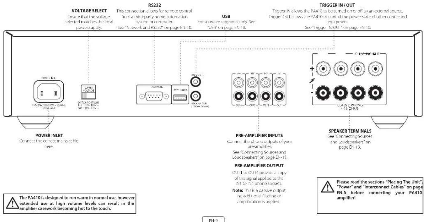
Rear Panel Connections and Controls PA410 EN-9
Control System Connections EN-10
Network and RS232 EN-10
USB EN-10
Trigger IN/OUT EN-10
EN-4
EN-6
Front Panel Connections and Controls EN-11
Operation
EN-12
Switching On EN-12
Automatic Standby EN-12
Network and RS322 in Standby EN-12
Muting the Output
EN-12
Mode switches
EN-12
Connecting Sources and Loudspeakers
Bridged Mono Mode - PA240 only
EN-16
Dual Mono / Bi Amp Mode - PA240 only
EN-17
Troubleshooting
EN-18
Specifications
EN-19
PA720
EN-19
PA240
EN-20
PA410
EN-21
Worldwide Guarantee
EN-22
Overview
Arcam's PA720, PA240 and PA410 amplifiers
Arcam's PA720, PA240 and PA410 power amplifiers provide class leading sound quality for the best reproduction of your music.
Drawing on the many years of amplifier design experience at Arcam, these products use the best quality components and engineering practice to produce amplifiers that will give many years of musical pleasure and reliable service.
With a toroidal based power supply, acoustically damped chassis class G technology (PA70 & PA720), parallel transistor output slags (PA70) and exceptionally low levels of distortion and noise, the PA720, PA740 and PA10 amplifiers are all capable of reproducing music with all its original authority and detail. Rest assures you will be hearing the music just as the artist intended.
The PA720, PA240 and PA410 amplifiers are designed to produce a level of performance that will truly bring music to life.
Placing The Unit
- Place the amplifier on a voltage firm surface, avoiding direct sunlight and sources of heat or damp.
Do not place the PA720, PA240 or PA410 on top of a power amplifier or other source of heat.
- Do not place the amplifier in an enclosed space such as a bookcase or closed cabinet unless there is good provision for ventilation. The PA770, PA240 and PA410 are designed to run warm during normal operation.
Do not place any other component or item on top of the amplifier as this may obstruct airflow around the heat sink, causing the amplifier to run hot. (The unit placed on top of the amplifier would become hot, too).
Do not place your record deck on top of the unit. Record decks are very sensitive to the noise generated by mains power supplies which will be heard as a background from if the record deck is too close.
The normal function of the unit may be disturbed strong electromagnetic interference. If this occurs, simply reset the unit with the power button, or move the unit to another location.
Interconnect Cables
We recommend the use of high-quality screened cables that are designed for the particular application. Other cables will have different impedance characteristics that will degrade the performance of your system (for Example, do not use cable intended for video use to carry audio signals). All cables should be kept as short as is practically possible.
It is good practice when connecting your equipment to make sure that the main power-supply cabling is kept as far away as possible from your audio cables. Failure to do so may result in unwanted noise in the audio signals.
Power
The amplifier is supplied with a moulded mains plug already fitted to the lead. Check that the plug supplied fits your supply - should you require a new mains lead, please contact your Arcam dealer.
If your mains supply voltage or mains plug is different, please contact your Arcan dealer immediately.
Push the IEC plug end of the power cable into the power socket on the back of the amplifier, making sure that it is pushed in firmly. Plug the other end of the cable into your main's socket and switch the socket on.
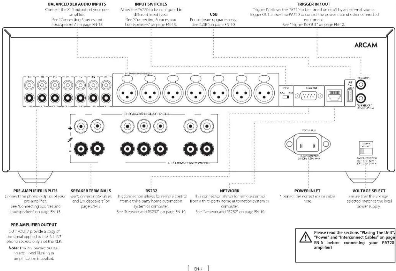
Rear Panel Connections and Controls PA720
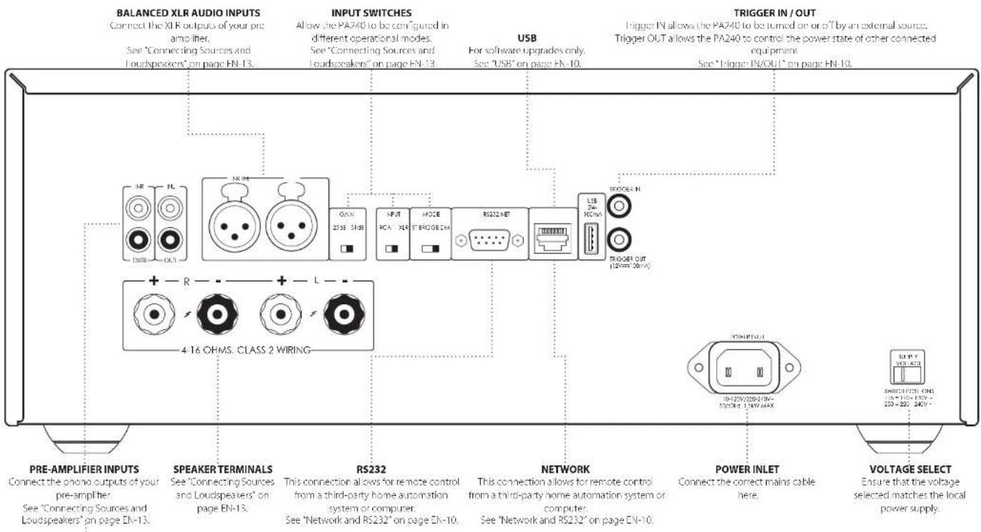
Rear Panel Connections and Controls PA240
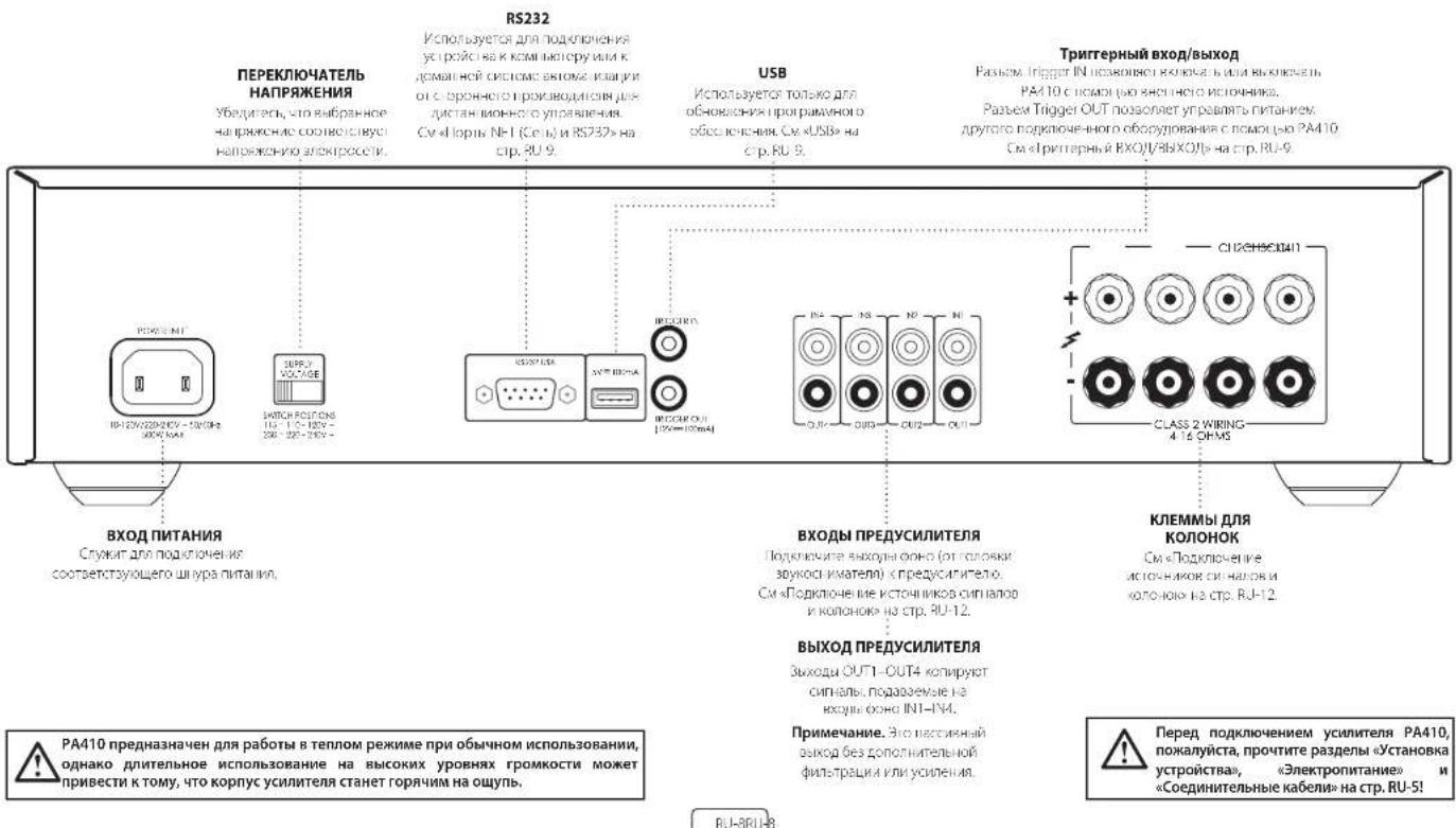
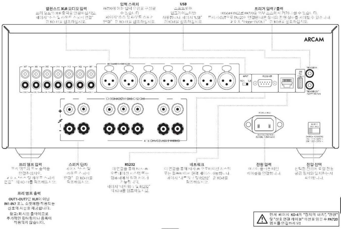
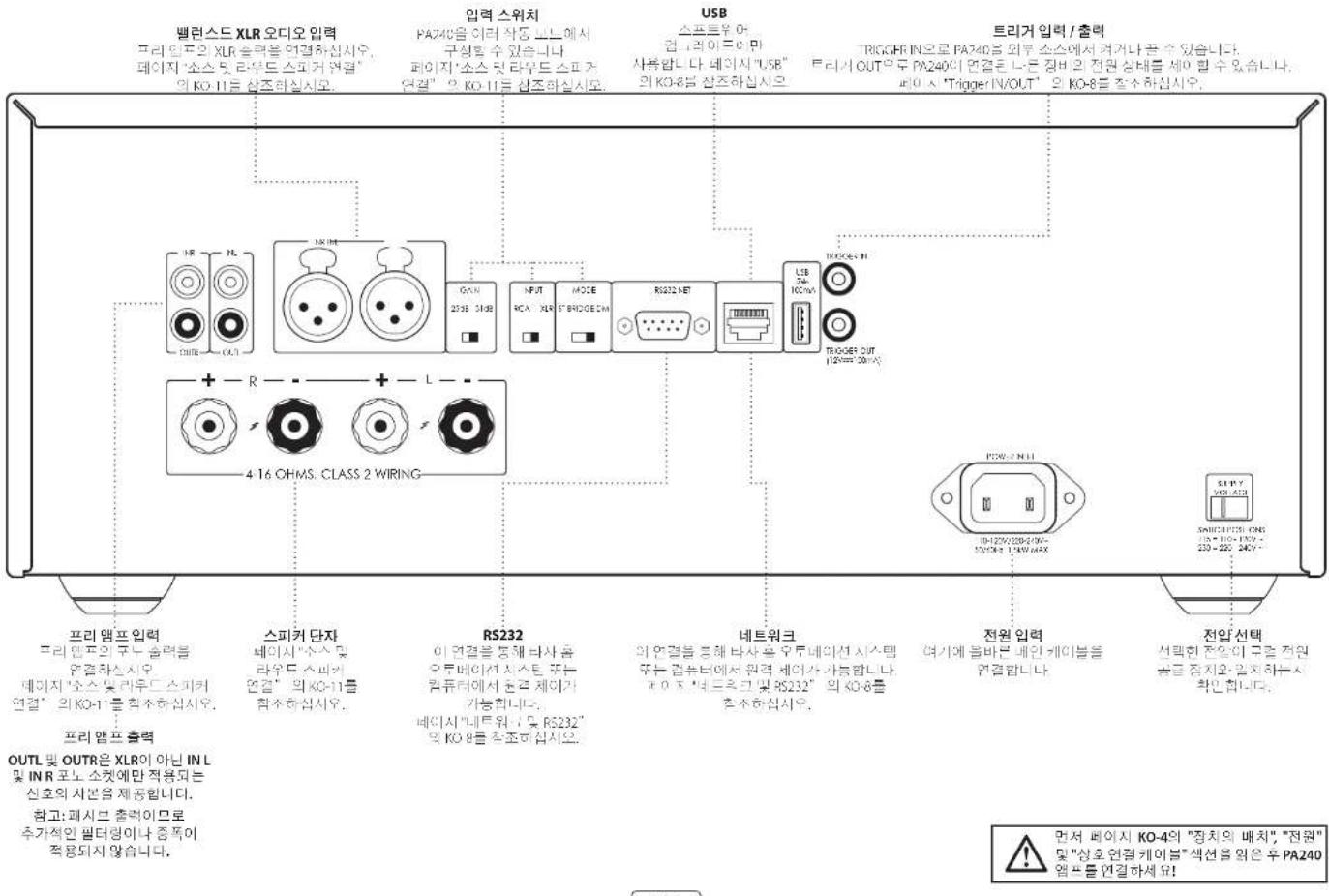
PRE-AMPLIFIER OUTPUT
OUTL and OUTR provide a copy of the signal applied to the IN L and IN R phono sockets only, noE, the 30 R
Note: This is a passive output, no additional filtering or amplification is applied.
EN-8
Please read the sections "Placing The Unit", "Power" and "Interconnect Cables" on page EN-6 before connecting your PA240 amplifier!

Control System Connections
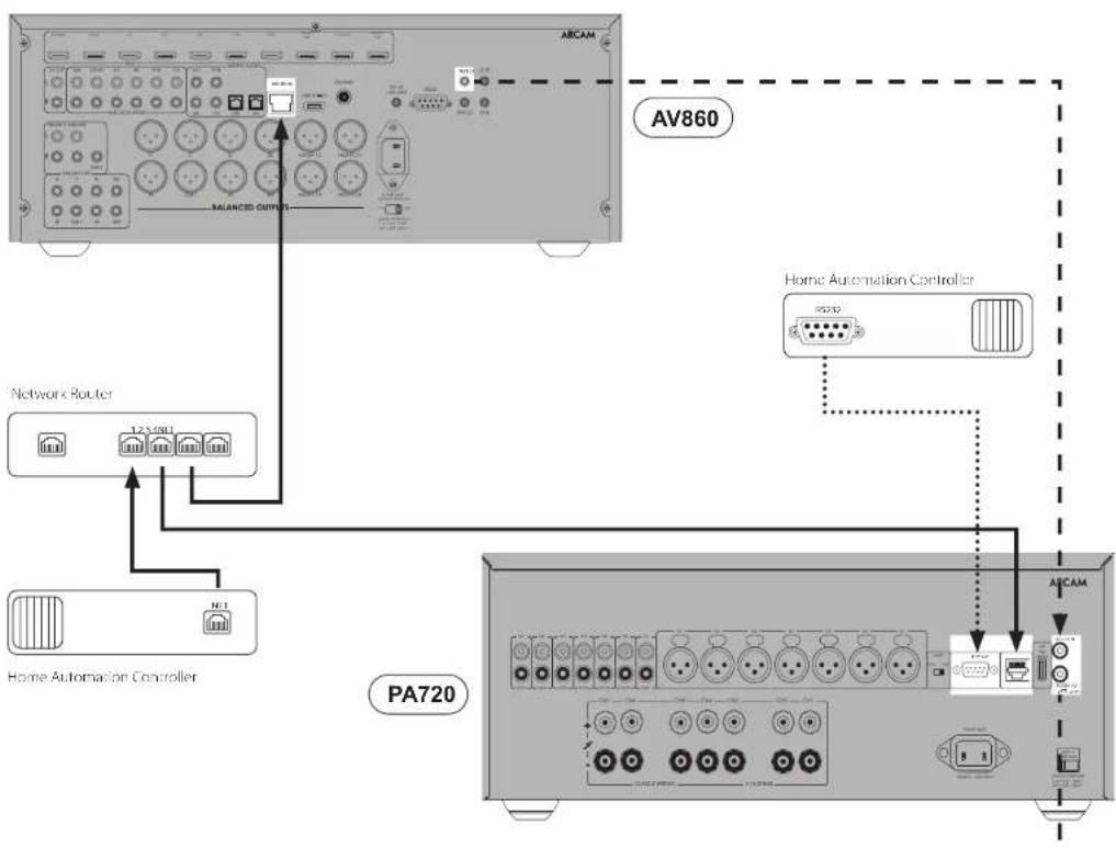
Network and RS232
The PA720, PA240 and PA410 feature a network and RS232 port that can be used to connect to a local network, computer or home automation system so that the amplifier can be controlled and monitored remotely. Various third party systems are available providing soonhisticated control over all of your entertainment devices. Contact your dealer or installer for details.
Her technical details of control protocols please refer to the PA720 / PA240 / PA410 RS232/P control document, available for download at www.arcam.co.uk, for further information.
Note By default, network and RS232 control is disabled in standby to minimise standby power consumption. To enable network control see "Network and RS232 in Standby" on page EN-12.
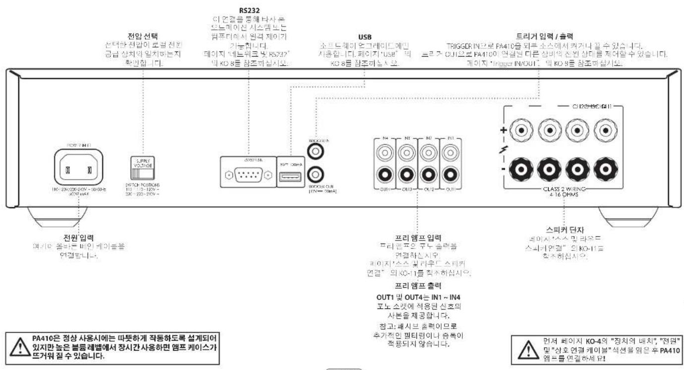
USB
The USB port is used for software updates on y. For the latest software as well as further information, please visit www.arcam.co.uk
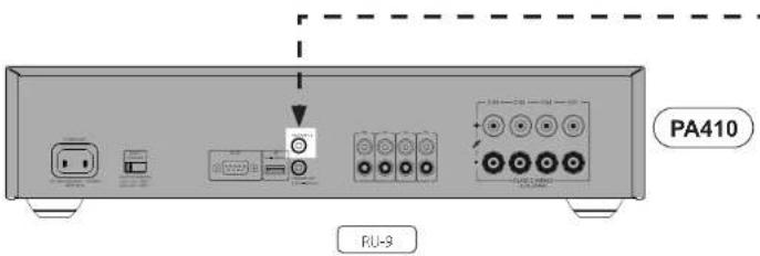
Trigger IN/OUT
The power state of the PA720, PA240 and PA410 can be controlled by compatible audio/video sources (such as an Arcam AVR). In this case, correct the TRICER OUT of the source to the TRICER IN of the PA720, PA240 or PA410 using a mono 3.5mm jack loss.
Similarly, this PA720, PA740 and PA410 can controll the power state of compatible product (such as another PA720, PA240 or PA410). In this case, connect the TRICOR-3N of the source to the TRICOR OUT of the PA720, PA240 or PA410 using a mono 3.5mm jack.
Note: These leads are not supplied.


Operation
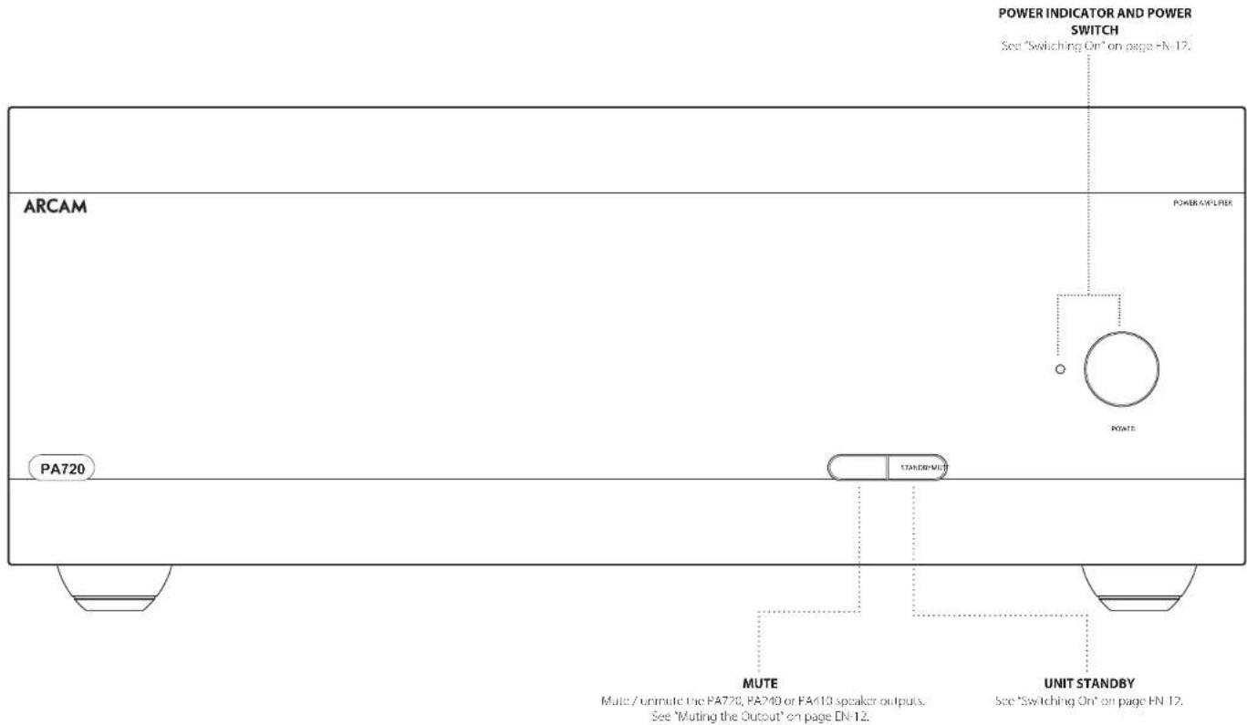
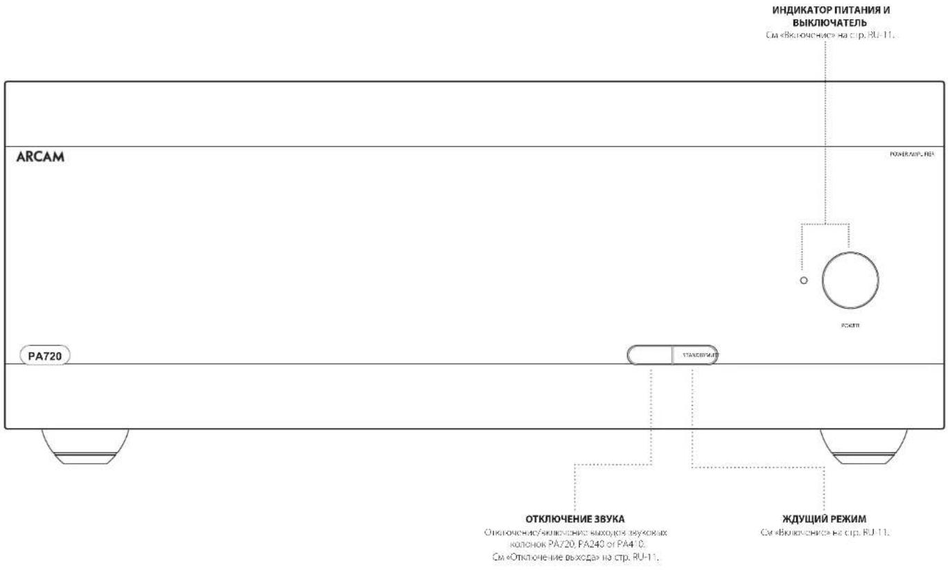
Switching On
The POWER button switches the unit on and off. The status indicator LED indicates the state of the amplifier. It changes from red to orange then white if mains power is connected and the unit is switched off. Pressing the STBY button while the unit is powered on, will place the PA720, PA240 or PA410 into standby mode. Press the STBY button again to bring the unit out of standby.
Automatic Standby
In order to comply with international regulations for consumer products, this unit is designed to enter standby mode if no user interaction and no audio input signal are detected for an extended period of time (default is 20 minutes). The unit can be brought out of standby by pressing the STBY button on the front panel, the trigger input or RS232 or ethernet command (if enabled, see 'Network and RS322 in Standboy' for more information).
The standby time out can be adjusted using either RS232 or IP control commands. Please refer to the PA720 / EA410 / PA410 RS232/IP control document, available for download from www.arcam.co.uk.
Alternatively pressing and holding the MUTE button will toggle the standby time out between OH and 20 minutes.
The LED will flash to indicate the setting change, red for OFF, green for 20 minutes.
Note: If the standby time-out is set to OFF, the automatic standby feature will be disabled.
Network and RS322 in Standby
In low power standby mode the network and RS322 functionality is disabled.
To enable network and RS232 in standby, send a control or status request command to the unit whilst it is powered on.
This will enable whichever control method was used when the unit is in standby.
Note: To indicate the unit is not in lowest power standby mode, the I/O will flash briefly when entering standby mode.
Note: Enabling network or RS232 control will increase standby power consumption. To restore the unit to the default low power standby consumption press and hold the STBY button for more than 3 seconds on each of the four factory units.
Muting the Output
The speaker outputs of the PA720, PA240 or PA410 can be silenced by pressing the MUTE button on either the front panel or by sending the relevant command via either the RS232 or network connection.
If the unit is muted, front panel power indicator will change to orange.
To cancel the mute, press the MUTE button again or send the relevant command via either the RS322 or network connection.
Mode switches
The various mode switches located on the rear of the PA720 and PA240 amplifiers allow you to configure your power amplifier to your specific equipment setup. See "Connecting Sources and Loudspeakers" on page 1-1 for more information.
INPUT (PA720 and PA240 only)
Tn's switch selects between the XLR and RCA phong inputs of the amplifier. Select which every connection method you are using to connect your preamp.
GAIN(PA240 only)
Tn's switch allows the gain to be changed from standard Arcam gain of 31 dB (with matches all Arcam amplifiers and receivers) to 2608. This allows flexibility to connect multie PA240 amplifiers in different modes to multiple speakers.
In normal set-ups this switch should be left at 31c8.
MODE (PA240 only)
Tn's switch selects between the different amplification modes of the PA740.
STEREO (ST)
This is the standard stereo amplification mode using two separate preamp inputs driving two separate speaker outputs.
DUAL MONO (DM)
This mode allows two separate speakers to be driven from a single preamp induct.
Alternatively the two drivers of a single speaker can be o-ampled from a single PA240.
BRIDGED MONO (BRIDGE)
This mode uses both channels of the PA240 to drive a single speaker. This the ultimate in high power, high fidelity amplification.
Connecting Sources and Loudspeakers
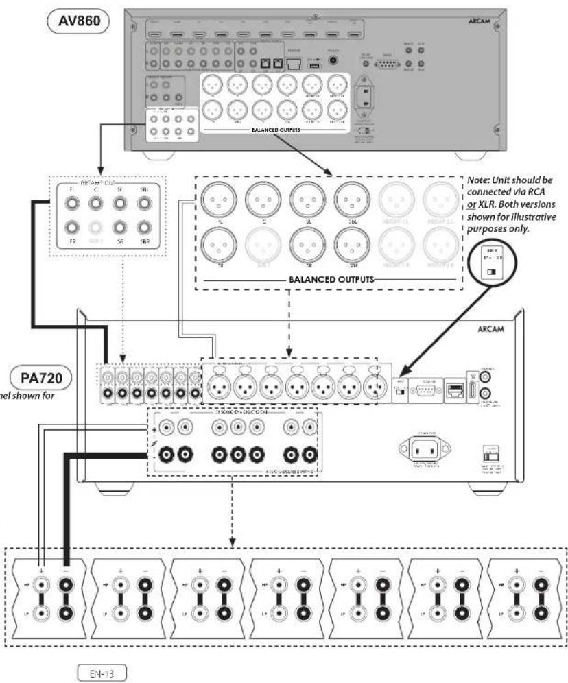
PA720
Connect the RED positive speaker terminal labelled CH1 to CH7+ to the positive terminal of your speaker. Similarly, connect the BLACK negative speaker terminal of the same channel to the negative terminal of your speaker.
Repeat this process for the other speakers, using the same respective input and speaker terminals for each channel.
NOTE: All the channels are identical so there is no requirement to connect specific AVR output channels to specific amplifier channels.
Notes On Making Speaker Connections
□ Do not make any connections on any amplifier while it is switched on. We recommend that your amplifier is completely disconnected from the mains supply before starting.
Before switching your amplifier on for the first time after connecting to speakers, please check all connections thoroughly. Ensure that bare wires or cables are not touching each other or the amplifier's chassis (which could cause short circuits), and that you have connected positive (+) to positive and negative (-) to negative. Be sure to check the wiring for both the amplifier and the speaker.
11 After making connections switch the amplifier on then gradually increase the volume to the required listening level.
If you are unsure as to how your system should be connected, please contact your Aram dealer who will be happy to help you.
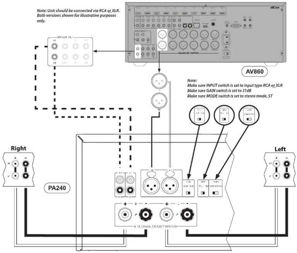
PA240
Connect the RED positive speaker terminal labelled L+ to the positive terminal of your speaker. Similarly, connect the BLACK negative speaker terminal labelled L- to the negative terminal of your speaker.
Repeat this process for the right speaker.
EN-14
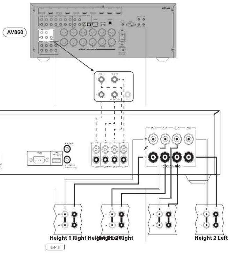
PA410
Connect the RED positive speaker terminal labelled CH1 to CH4+ to the positive terminal of your speaker. Similarly, connect the BLACK negative speaker terminal of the same channel to the negative terminal of your speaker.
Repeat this process for the other speakers, using the same respective input and speaker terminals for each channel.
NOTE: All the channels are identical so there is no requirement to connect specific AVR output channels to specific amplifier channels.
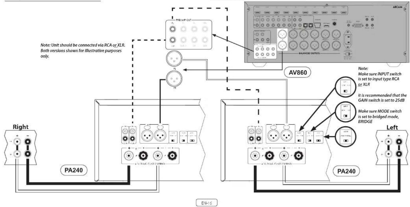
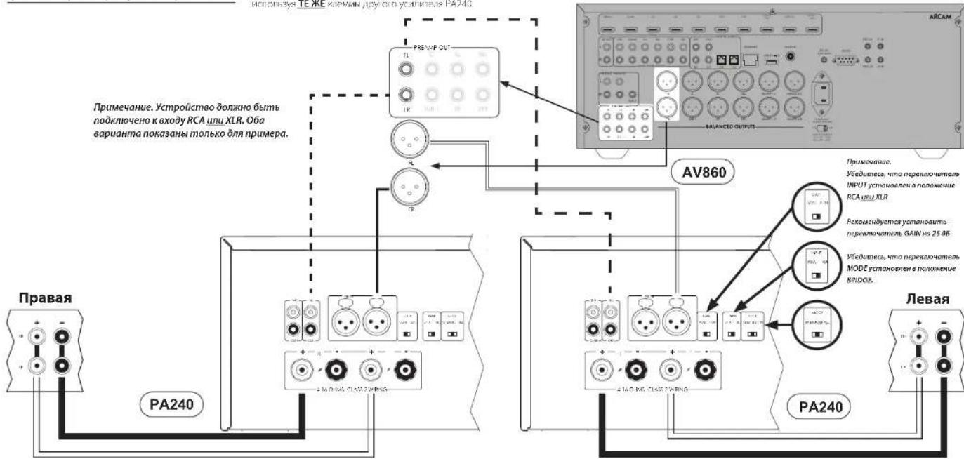
Bridged Mono Mode - PA240 only
Bridged mono mode requires the use of a PA260 for each channel.
Note: in bridged mode only the L+ and R+ speaker outputs are required.
WARNING: Do not make any connections to the L- or R- speaker terminals, doing so will severely damage your amplifier.
On one of the PA240s, connect the RED positive speaker terminal labeled L+ to the positive terminal of your left speaker.
Connect the RED positive speaker terminal labeled R+ to the negative terminal of your left speaker.
Repeat this process for the right speaker, using the SAME terminations on the other PA240.
Note: L+ must be connected to the positive speaker terminal and R+ to the negative speaker terminal on BOTH speakers otherwise the speakers will be out of phase.
WARNING: Make ABSOLUTELY sure you have used the L+ and R+ terminals of the PA240. L- and R- terminals are not required in this arrangement.
In this setup only one interconnect is required to each power amplifier and it should be connected to the IN L input. The interconnects can be either XLR (recommended for longer cable runs) or phono (RCN). Set the INPUT switch on both of the PA240's to the appropriate setting for the cables used.
Note: The IN R input has no function in this arrangement.

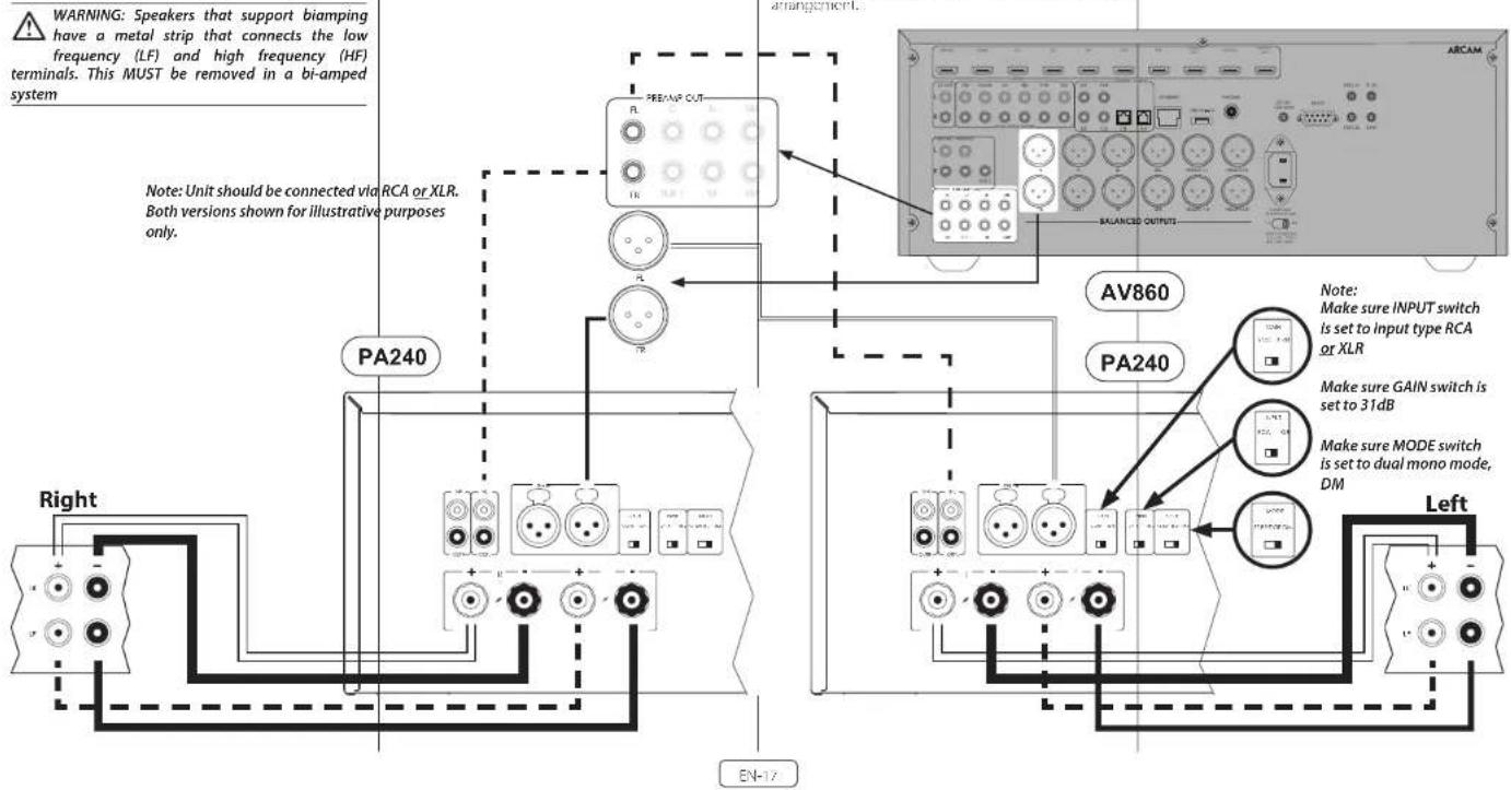
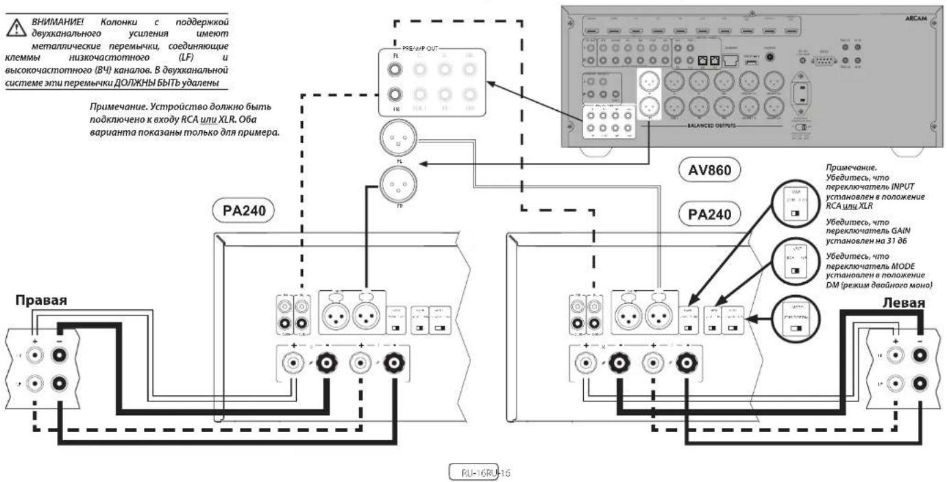
Dual mono requires the use of a PA240 for each channel. On one of the FA240's, connect the RED positive speaker terminal labeled L+ to the positive I- terminal of your left speaker. Similarly, connect the BLACK negative speaker terminal labeled L- to the negative I- terminal of your left speaker.
WARNING: Speakers that support biampling have a metal strip that connects the low frequency (LF) and high frequency (HF) terminals. This MUST be removed in a bi-amped system
Using a second speaker cable connect the RED positive speaker terminal labelled R+ to the positive HF terminal of your left speaker. Similarly, connect the BLACK negative speaker terminal labelled R- to the negative HF terminal of your speaker.
Repeat on the process for the right speaker, using the same terminals on the other PA249.
In this setup only one interconnect is required to each power amplifier and it should be connected to the IN L input. The interconnects can be either XLR (recommended for longer cable runs) or phono (RCA). Set the INPUT switch on both of the PA240's to the appropriate setting for the cables used.
Note: The IN R input has no function in this arrangement.
Troubleshooting
| Problem Check the following | |
| No sound | ☐ The PA720 / PA240 / PA410 power amplifier is correctly plugged in and switched on. ☐ Your audio/video source (e.g. pre amplifier) is correctly connected. ☐ The PA720 / PA240 / PA410 is not in protection mode, as described in the next section. ☐ The PA720, PA240 and PA410 is not muted. |
| Sound cuts cut unexpectedly | The PA720 / PA240 / PA410 may encir or a protection mode, depending on the fault being detected. The front panel LED will indicate the fault type, according to the list below. ☐ H ASHING WHILH: The internal temperature of the unit reached an unsafe level. Allow the PA720 / PA240 / PA410 to cool off. ☐ FLASHING RED: The PA720 / PA240 / PA410 amplifier detects speaker short circuit. Should this happen, please inspect all the speaker cables to make sure none of them are shorted together. This fault is very common when bare wires are being used to make speaker connections. ☐ FLASHING ORANGE: PA720 and PA240 only. The amplifier detects DC offset. Following any of the faults described above, the amplifier will turn itself off and power to the speakers will be removed. To continue using the PA720 / PA240 / PA410, the fault must be removed and the unit must be turned OFF then back ON. |
Specifications
PA720
| Continuous power output at 0.2% THD per channel | ||
| Seven channels driven, 4Ω / 8Ω, 1kHz 140W / 100W | ||
| Five channels driven, 4Ω / 8Ω, 1kHz 175W / 110W | ||
| Two channels driven, 4Ω / 8Ω, 1kHz 225W / 140W | ||
| Harmonic distortion, 80% power, 8Ω at 1 kHz 0.90Ω | ||
| Inputs | ||
| RCA Type XLR Type | ||
| Input sensitivity 100W / 8Ω 800mW RMS 1.6V RMS | ||
| Signal/Noise ratio (A-wild) 100W / 8Ω 110dB | ||
| Input impedance: 10kΩ | ||
| Frequency response 20 - 20kHz +/-0.05dB | ||
| General | ||
| Mains voltage 110-120V or 220-240V, 50-60Hz | ||
| Maximum power consumption 1.5kW | ||
| Low power standby consumption | ||
| Network standby consumption 2W | ||
| Dimensions W x H x D (including feet, control knob and speaker terminals) | ||
| Weight (net) | 18kg | |
| Weight (gross) | 19.7kg | |
All specification values are typical unless otherwise stated. Arcam has a policy of continuous improvement for its products. This means that designs and specifications are subject to change without notice. E&OE.
EN-19
Continuous power output at 0.2% THD per channel
| Two channels driven, 40/80, 1kHz 380W / 225W | |
| One channel driven, 80 bridged mode, 1kHz | 790W |
| Harmonic distortion, 80% power, 8Ω at 1kHz 0.01% | |
Inputs
| RCA Type XLR Type | ||
| 31dB 25dB | 31dB 25dB | |
| Input sensitivity 700W / 8Ω 1.15V RMS 2.3V RMS | 7.3V RMS 4.6V RMS | |
| Signal/Noise ratio (A-wtd) 10W / 80Ω 110dB 114dB 110dB 114dB | ||
| Input impedance 10kΩ | ||
| Frequency response 20-20kHz +/-0.05dB | ||
General
| Mains voltage | 110-120V or 220-240V, 50-60Hz |
| Maximum power consumption | 1.5kW |
| Low power standby consumption | 0.5W |
| Network standby consumption | 2W |
| Dimensions W x H x D (including feet, control knob and speaker terminals) | 433 x 425 x 177mm |
| Weight (net) | 18kg |
| Weight (gross) | 19.7kg |
All specification values are typical unless otherwise stated. Arcam has a policy of continuous improvement for its products. This means that designs and specifications are subject to change without notice. E&OE.
| Continuous power output at 0.2%THD per channel | |
| Four channels driven, 40/80, 1kHz/70W / 50W | |
| Two channels driven, 40/80, 1kHz 90W / 60W | |
| Harmonic distortion, 80% power, 8Ω at 1kHz 0.03% | |
| Inputs | |
| Input: sensitivity 50W / 8Ω 560mV RMS | |
| Signal/Voise ratio (A:wid) 50W / 8Ω 1.06dB | |
| Input: Impedance 10kΩ | |
| Frequency response: 70 - 20kHz +/- 0.2dB | |
| General | |
| Mains voltage 110 120V or 220 240V, 50 60Hz | |
| Maximum power consumption 700W | |
| Low power standby consumption 0.5W | |
| Dimensions W x H x D (including feet, control knob and speaker terminals) | 433x325x105mm |
| Weight (net) 10kg | |
| Weight (gross) 11.5kg | |
All specification values are typical unless otherwise stated. Arcam has a policy of continuous improvement for its products. This means that designs and specifications are subject to change without notice. E&OE.
EN-21
Worldwide Guarantee
This entitles you to have the unit repaired free of charge, during the first five years after purchase, provided that it was originally purchased from an authorities-Ascram dealer. The Ascram dealer is responsible for all after sales service. The manufacturer can take no responsibility for defects arising from accident, misuse, abuse, wear and tear, neglect or through unauthorised adjustment and/or repair, neither can they accept responsibility for damage or loss occurring during transit or from the person claiming under use quarantine.
The warranty covers:
Parts (excluding disc drives) and labour costs for five years from the purchase date (see below for additional terms and conditions). After five years you must pay for both parts and labour costs.
Disc drives (of any type) are covered under this warranty for two years from the purchase date.
The warranty does not cover battery replacement at any time.
The warranty does not cover transportation costs at any time.
Claims under guarantee
This equipment should be packed in the original packing and returned to the dealer from whom it was purchased. It should be sent carriage prepaid by a repuable carrier—not by post. No responsibility can be accepted for the unit whilst in transit to the dealer or distributor and customers are therefore advised to insure the unit against loss or damage whilst in transit.
For further details contact Arcam at arcam/support@harman.co.uk.
Problems?
If your Arcam dealer is unable to answer any query regarding this or any other Arcam product please contact Arcam Customer Support at the above address and we will do our best to help you.
On-line registration
You can register your product online at www.arcam.co.uk.
MANUEL

ARCAM HDA
AMPLIFICATEUR
PA720 / PA240 / PA410
Bienvenue
Votre equipe de conception PA720, PA240 and PA410
Contenu
Bienvenue
FR-2
Vue d'ensemble FR-4
Les amplificateurs Arcam PA720, PA240 and PA410
MODE (PA240 seizure)
PA720 / PA240 / PA410
Willkommen
PA720 / PA240 / PA410
Welkom
Arcam's PA720, PA240 and PA410 versterkers
BRIDGED MONO (BRIDGE)
PA720 / PA240 / PA410
Bienvenido
PA720, PA240 and PA410 de
Arcam
BRIDGED MONO (BRIDGE)
PA720 / PA240 / PA410
BAKHbIE INHCTPYKUNI NO TEXHNKE BE3ONACHOCTN
| Toproban MAPK:ARCAM | |
| Habatien He tobaap:YcHInTeB.8yKoOoN 10ctotbl | |
| Vstotoboten:XaOMAH INI terpHeunn Nlaacpyu HmKoppeRan, CILIA 06901 KoHNeknkyT.F.CrAmFpD,ATzAnTHK Cptn400,odmc 1500 | |
| Cipera IpcnckxwUdHk Ktaih | |
| ImiOpEep R PoCCNO:OOO "XAPMAH PUC,CAApEe,PoSSn,177018,1MocKnBa,yL,IqvnHcs, n17, k1 | |
| TapanHHnHne pereon;5 net | |
| MInfOpMaun o cepaclnhx uenHpaX. Htp://harman.club/servicecenters/arcam.10+7-800-700-0467 | |
| Cxxk cJykbnc 5 net | |
| ToBaP seprnHicpoBaan | EAC |
| Dipta IprvAusbudct hata:Data niz ToBANCHN yecOcOBIN Bn CpIcBnCTER nDyHM ByKsChHnN obO3IaJeHMMn IBropor prpmybI cymonos cepinHoro POMepa Iaedn, chcybouXn noche paadentnHb-Iro Oyakz «, KoPcBocBn CnOaHg,BycHnOy,BycHnOy,BycHnOy,BycHnOy,BycHnOy, PraaBnCn, RnBnBn,2012/Cge,2012/Cge,2012/Cge,2012/Cge, PraaBnCn, RnBnBn,2012/Cge,2012/Cge,2012/Cge, PraaBnCn, RnBnBn,2012/Cge,2012/Cge,2012/Cge, PraaBnCn, RnBnBn,2012/Cge,2012/Cge,2012/Cge,2012/Cge,2012/Cge,2012/Cge,2012/Cge,2012/Cge,2012/Cge,2012/Cge,2012/Cge,2012/Cge,2012/Cge,2012/Cge,2012/Cge, 2012/Cge,2012/Cge,2012/Cge,2012/Cge,2012/Cge,2012/Cge,2012/Cge,2012/Cge,2012/Cge,2012/Cge,2012/Cge,2012/Cge,2012/Cge,2012/Cge,2C |
YIOHJIOI YCYTOCHIO TLOIKO HO TPOHOMY KENHICHKO S CDOICUBI C HUPCIOHICHKO HNCIPKURKE, HC NUI CCLCAMONHOHIOK BHKSHAIK OOP KIOU OLOP DQ CYCCBILIM BCPOM, B CIOU ODEOHCKHAYH NEOHOTAO KNOOHNIOOIEA 3A PAHAPINN NOOHNIOOIA MRCO OOCNHOVA AHCIOHOTAO, OOCHEYOCNHOX PAXHNIH, PEXIHANOLK A (D) TMNTHCRPTOPKHO, HNDNHOVCAOHO, HNDNHOVCAOHO, HNDNHOVCAOHO, HNDNHOVCAOHO, HNDNHOVCAOHO, HNDNHOVCAOHO, HNDNHOVCAOHO, HNDNHOVCAOHO, HNDNHOVCAOHO, HNDNHOVCAOHO, HNDNHOVCAOHO, HNDNHOVCAOHo, YCYTOCHIO TPOIKO HNCIPKURKE JBI PABOOI S NKHIXK, CPOK IOHOTAO HC NUI PCHNK CHIOHOK CHYTOHOK XPHENCHO
PnPBcTCTBn
Cnacn6o 3a okazahHoe HAM DOBepne n no3dpabnem...
CHOBYKOJyCNHIOBMOHOCIN Arcm PA720,PA240 or PA410.
KOMANAR ASCR BUNYCKAET CNEHANBAPROBAAHYU AUYAANATAPATyI BUCOHAMILERO KAHCTBAYK OBOE BHTBPE decANTHETM.YCINANTHUMMOHOTCNCEPA7202A430 AND PA410 ANONCA HOEOHMMN P3PABOTKAM 3 H-3HIMPOKEM YCTPOCTA KNACCA HI-H. KOCHPYRAU CPER HDA OCMPTAHA TBAEC BOSHTM ORTH ARACM, OJHNI IN CAMAX I PCOLOHNOKOMIAH BOCIKOBPIAHN BUNYCKAOIH NAYBANIHIOCSOBOPYJMOHNC.CEPIN MHOAGALHIX YCIPOTIC MOHOTCA ARACMI, OUPKOLIBACH NPHOBUBOOHMMI DJOHCM, IOBOHIT BAM NHOOI NETIOHLYI BYDOKTREI GTOXPPYTAHMSYMAH
HaHnOeIpyoCIOIOIOIOIOIOIOIOIOIOIOIOIOIOIOIOIOIOIOIOIOIOIOIOIOIOIOIOIOIOIOIOIOIOIOIOIOIOIOIOIOIOIOIOIOIOIOIOIOIOIOIOIOIOIOIOIOIOIOIOIOIOIOIOIOIOIOIOIOIOIOIOIOIOIOIOIOIOIOIOIOIOIOIOIOIOIOIOIOIOIOIOIOIOIOIOIOIOIOOO
Ma Hanece, C Hane CE TcXtOIOIIOIOIOIOIOIOIOIOIOIOIOIOIOIOIOIOIOIOIOIOIOIOIOIOIOIOIOIOIOIOIOIOIOIOIOIOIOIOIOIOIOIOIOIOIOIOIOIOIOIOIOIOIOIOIOIOIOIOIOIOIOIOIOIOIOIOIOIOIOIOIOIOIOIOIOIOIOIOIOIOIOIOIOIOIOIO
Komanda cneuaanctob no pa3pa6otke PA720, PA240 and PA410
Copepkanne
BAKHbIE INHCTPYKUNI NO TEXHNIKE BE3ONACHOCTN RU-2
PnPBETBne
0630p
YCTAHOBKa YCTPOINCTBa RU-5
CoeHHTenbHe KaeRu-5
3ncktponntaHRCU-5
Pa3bembl nIeMeHtbl ynpabHeHHa 3aHne naHenn PA720 RU-6
Pa3bEmbln 3neMeHTbI ynpabHeHna3aHne naHEn PA240 RU-7
Pa3bembl nIeMeHtby npBnHeHa 3aHne naHn PA410 RU-8
TIOKJIIOUeHHe cNCTeMbI ynpaBnEHRA RU-9
NopTbNET(CeTb)R RS232 RU-9
USB RU-9
Tprrpbrn BXO/ BblXoD RU-9
RU-3
RU-5
3nementbI ynpabneHn npa3beMbHa nepeDne naHn RU-10
3KcnnyataaynyctpoCTBaRU-11
BKINIOHNE RU-11
AeTOMaTueckoe nepeeknoucHne B pexm OxpaHNA RU-11
ФункдулpennoCHTNuepe3noptRS322BpckmOxuaHn
OTKIOUCHNC BbXoDa
Ipeeknucatenn pekmob
RU-11
RU-11
RU-11
IopKluoyehme NCTOuyHKnOB CnHaNoB I KOHOHOK
MocTOBOI peKIM MOHO -TOnbKO dNPA240
Pexm DboHoro MoHO /DbyXkHaHbIoro ycnneHn -Tobxo pna PA240
RU-12
RU-15
YcTpaHHeH HeuCnpaBHOCTeI
TexHuecknXapaKTePncTKn
PA/20
PA240
PA110
RU-18
RU-18
RU-19
RU-20
MekdyhapoHaHrapaHTn
RU-21
0630p
Ycnnntn Arcam PA720,PA240 and PA410
XyHNTHENK MOHIOCTN Arcam PA720, PA240 and PA410
OeCEeIeBAHT BHOCHAIUE KNECTSO 58V3 D CBOEM
KIOECDU HINIOHIOO OIOIOIOIOIOIOIOIOIOIOIOIOIOIOIOIOIOIOIOIOIOIOIOIOIOIOIOIOIOIOIOIOIOIOIOIOIOIOIOIOIOIOIOIOIOIOIOIOIOIOIOIOIOIOIOIOIOIOIOIOIOIOIOIOIOIOIOIOIOIOIOIO
YnHnHnHnHnHnHnHnHnHnHnHnHnHnHnHnHnHnHnHnHnHnHnHnHnHnHnHnHnHnHnHnHnHnHnHnHnHnHnHnHnHnHnHnHnHnHnHnHnHnHn HNHNHNHNHNHNHNHNHNHNHNHNHNHNHNHNHNHNHNHNHNHNHNHNHNHNHNHNHNHNHNHNHNHNHNHNHNHNHNHNHNHNHNHNHNHNHNHNHNHNHNHNHNHNHNHNHNHNHNHNHNHNHNHNHNHNHNHNHNHNHNHNHNHNHNHNHNHN
VIOIOIIOIOIOIOIOIOIOIOIOIOIOIOIOIOIOIOIOIOIOIOIOIOIOIOIOIOIOIOIOIOIOIOIOIOIOIOIOIOIOIOIOIOIOIOIOIOIOIOIOIOIOIOIOIOIOIOIOIOIOIOIOIOIOIOIOIOIOIOIOIOIOIOIOIOIOIOIOIOIOIOIOIOIOIOIOIOIOIOIOIOIOIOIOIOIOIOIOIOIO
YUBINCHI P7A20, PA70 and PA70-10 HONOBBI CEFATB My351K NHCIAHCTONLUMY KUNDU.
yCTaHOBka yCTpoIcTbA
YHOHOHOHOHOHOHOHOHOHOHOHOHOHOHOHOHOHOHOHOHOHOHOHOHOHOHOHOHOHOHOHOHOHOHOHOHOHOHOHOHOHOHOHOHOHOHOHOHOHOHOHOHOHOHOHOHOHOHOHOHOHOHOHOHOHOHOHOHOHOHOHOHOHOHOHOHOHOHOHOHOHOHOHOHOHOHOHO HOHOOOHHOOHHOOHHOOHHOOHHOOHHOOHHOOHHOOHHOOHHOOHHOOHHOOHHOOHHOOHHOOHHOOHHOOHHOOHHOOHHOOHHOOHHOOHHOOHHOOHHOOHHOOHHOOHHOOHHOOHHOOHHOOHHOOHHOOHHOOHHOOHHOOHHOOHHOOHHOOHHOOHHOOHHOOHHOOHHOOHHOOHHOOHHOOHHOOHHOOHHOOHHOHHOOHHOOHHOOHHOOHHOOHHOOHHOOHHOOHHOOHHOOHHOOHHOOHHOOHHOOHHOOHHOOHHOOHHOOHHOOHHOOHHOOHHOOHHOOHHOOHHOOHHOOHHOOHHOOHHOOHHOOHHOOHHOOHHOOHHOOHHOOHHOOHHOOHHOOHHO HHO Hoo HHo HHo HHo HHo HHo HHo HHo HHo HHo HHo HHo HHo HHo HHo HHo HHo HHo HHo HHo HHo HHo HHo HHo HHo HHo HHo HHo HHo HHo HHo HHo HHo HHo HHo HHo HHo HHo HHo HHo HHo HHo HHo HHo HHo HHo HHo HHo HHo HHo HHo HHO Hoo Hoo Hoo Hoo Hoo Hoo Hoo Hoo Hoo Hoo Hoo Hoo Hoo Hoo Hoo Hoo Hoo Hoo Hoo Hoo Hoo Hoo Hoo Hoo Hoo Hoo Hoo Hoo Hoo Hoo Hoo Hoo Hoo Hoo Hoo Hoo Hoo Hoo Hoo Hoo Hoo Hoo Hoo Hoo Hoo Hoo Hoo Hoo Hoo Hoo Hho HHO OOH OH OH OH OH OH OH OH OH OH OH OH OH OH OH OH OH OH OH OH OH OH OH OH OH OH OH OH OH OH OH OH OH OH OH OH OH OH OH OH OH OH OH OH OH OH OH OH OH OH OH OH OH OH OH OH OH OH OH OH OH OH OH OH OH OH OH OH OH OH OH OH OH OH OH OH OH OH OH OH OH OH OH OH OH OH OH OH OH OH OH OH OH OH OH OH OH OH OH
H He ytaaannnnae PA720 PA410 or PA10 Hpytue yenmncn MCHHOINI KAKMIOHCTOHNBNTFRA.
He yctnabtny ycnntteb 8sakpnBnnpocpacthe. Harpwep 3 kHKnKmKdOyA M0 32KcPtoCToKe, eOnn TmE ObecTeHea Xopou7eBemnnnIy, YcknTnePAV20, PA240 and PA410 MNy. Harpwcpch 30 KpOen HcMnMnHgB60
Hn Pn Hn Hn Hn Hn Hn Hn Hn Hn Hn Hn Hn Hn Hn Hn Hn Hn Hn Hn Hn Hn Hn Hn Hn Hn Hn Hn Hn Hn Hn Hn Hn Hn Hn Hn Hn Hn Hn Hn Hn Hn Hn Hn Hn Hn Hn Hn Hn Hn Hn Hn
H He yanaarabae Hekpnpnphnna Hyaepnnc. 3kckponcompbaaon OeHs 4ycbTBeBnH K NOVAM COnbbs NnAHH Aakmocn BnAanrOcNnCnIynn, nOooy HC paacnBaTc hKpOePOMnBnBnCHnEeK
Hopnne HnyknoHpnoa HycOIO MOKAT BHTN HApuyHO B DpyTtAeKoRbAeBcTb CNTbHbONrPoAMTNbX NcM 3 TOMCryAe NpeBaayyIyCTY pOyTOBcN CMOHbIO KONIKY OTHAHIN YIAYAOHOTERgOgDyCMAETe.
CoeHHTeBHe k6eHn
yCipO1nTa, 5nKpnI0mTae
CoenHnBHe Bk6bHa CTp. RU-5
Pa3bemblnneMeHbIy npabHeHa 3aHne nanePA410
IopKnIOUeHnE CnCTEmbl ynpabLeHHa
NopTBI NET (Cetb) n RS232
YtOPOIcTO PA/20, PA/40 are PA/106 oOpyoaoa- cTeKTHNNOPTMNI PABHOMRPS232,KOTOPMEyRHTCHTbO8OCTBILPQIOKTOHENHKOKAHTBOH CETM K KOMBIOTBEYIKN KCTCSEVEOLOHNEBETOMNTKALIKU, QIOJIIEJXINJHOHOYIOIPARIBYOSUC.
Pamnnae caccene cccoponnnnnpnnnppnnnne nncnnnnnne nnnnnnnnne nnnnnnnnne nnnnnnnnne nnnnnnnnne nnnnnnnnne nnnnnnnnne nnnnnnnnne nnnnnnnnne nnnnnnnnne nnnnnnnnne nnnnnnnnne nnnnnnnnne nnnnnnnnne nnnnnnnnne nnnnnnne nannnnnne nannnnnne nannnnnne nannnnnne nannnnnne nannnnnne nannnnnne nannnnnne nannnnnne nannnnnne nannnnnne nannnnnne nannnnnne nannnnnne nannnnnne nannnnnne nannnnnne nannnnnne nannnnnne nannnnnne nennnnnne nannnnnne nannnnnne nannnnnne nannnnnne nannnnnne nannnnnne nannnnnne nannnnnne nannnnnne nannnnnne nannnnnne nannnnnne nannnnnne nannnnnne nannnnnne nannnnnne nannnnnne nannnnnne nannnnnne narnnnnne nannnee
1xHnncnncn HpOcbnncn HpOccknncn 1ybnnnnncn npnnnnn n Bnnpynnnn n PPA20/PA240/PA410 npees R5232/P, KOTpBn MmNkCnAeB6eBnEw wwwarcam.co.n
PnnpmnaeNo yknohnaHynpaaBne Hpees npnt NFT n RS230 anokno h B peeknckn aKnnn, no 1000 mnnnepo3b Hpeopnnpoepe. No 800 bknnohty npanae no cetn cn paeden kynnniyn npaaane n no cetn n hepees noprr RS232 B peknke okaaahne h naCPT,RU-11.
USB
Pabom USM NcHbUcIe CmKIO pR 06CnHOHNOpAMMOO OecBcHHeN. OcHOBcHIO, a TAKKE BCO HEOxDMyu HOpMaHo MOHO HAIINa cAcapw www.arcam.co.K
TprrrepHbBxOa/BblXoD
Cocronemn mnnn FA720, PA240 and PA410 mo hno ynpnepn c novnnoe coeehnx npyipnBvye ypOHToK (TANK KAK yDNO Bnpepepeep Acm). Dn pcoonnpknoe TnrrreepbBxog (TRICER OUT) yPOnTOA ynpaennein k Tnptreepmoxy (TIGGER IN yannnna FA720, PA240 or FA10, nncnna MOHOPINNEK Kabe CcBEMN 35 M
TeHIOI TAK XE YANAMINPA720, PA240 and PA410 MYOT yypABNTB NTAPAHM CORSETPMOYCTOPBETA (HAPWPE, DYPOYONOMYAT720, PA240 or PA410.8 B HCMCHNCHNCHNCHNCHNCHNCHNCHNCHNCHNCHNCHNCHNCHNCHNCHNCHNCHNCHNCHNCHNCHNCHNCHNCHNCHNCHNCHNCHNCHNCHNCHNCHNCHNCHNCHNCHNCHNCHNCHNCHNCHNCHNCHNCHNCHNCHNCHNCHNCHNCH
PnmeaHm.ynovnytBbde kcbet a bckntent

3IeMeHbI ynpabHeHn npa3beMbHa nepeDne naHenn
PU-0
3KcnnyataunyyctpoNCTBa
BkIOueHne
KIOHKAPOWRAIIEpEeHHRnAHcRcHHTN D KINKHOHN HbBKNKHOHN YCtPcO7Ba. CoCTOBHNE yCNTHENOpFpEnEDETCN C NOMOUBa CSeTOHNO HIOHHPKUHKOPOK KOYJyCtPcO130 HOKMOHCHO K cCNI TANHNO HO BBOHOHO, MHIIBHOTOSO CPKCHHM UTeTON PnONKHOHN YCtPcO7Ba C NOMOUBA KINKHOHN TANHNO AHHNLOD BATCPoTcH CHMNAI ODECKHNN, bAATG EHTNTOH.
KAKHAPTE KONIKI STBY R to apnma, kortla yctpnoTtAC BKNIOHO, neknoAeAe FA720, PA240 or FA410 a pexnovocda H. Postopuice kakte KONIE STBY BANCPOYIC 1600 POMNIN DOKHJH
ABTomatuecheckoe nepekniouehenbpeKIM OXnDaHn
BDBRc coBDHbMnKHyDpHbI KpAIBB B OTHOEIMNOTPeBETBCIKXTOASPOB DAIOE yCPOKCTBO OTOMAMNECKRepeKIOeTcE BPEKM OKOABAH, ECBI T ETEHE DITINBOH NEPPOPA BPEHMHET HIKAKOK, AIEHOATGNTNPOBZoTeTNI HxOBDKOxOHTCYAOyAudHOCINAIH (NOYMONHINIO 2WmY)Y. CPOPCTBO MOKOJI KUTBISACHO HPCOMNOLMOHDMHNAMHCMKONSTBY Hn HOPCHIOHNNV, A IHKKIOHNOHNKOMBEHIIHOPCSI INPCHNCCXHXN, NK3732 aHHNHCIC (KCNH H cyHnHnKBOHNCN, pOHIOHNOHNK, JIOHOHNHCHIOH NO HOPMPOMA CM, pAENIyE KUPMKN YUAPBNHINNO n cnnrA HOP331 (RS372 B POKMIK OMOHAN
Bbma Taaytaa nnepeoia p eonkoknnae mnoho aagab kohmshyynpapnenepees F5237/ Ic. cyjmyen cnypapnene PA720 /PA240 /PA140 neoe 5323/PI, KOTOPA MNOHO cnahtbe66calne www.aramc.co.uk
B K3HCTE 2AETREPIATNBU,1K3KTHY AYEKO30314HEKHO BMT MUTE K9KIOKIOIIPKIMKOKOIBINMOTYOFFT 20 MHTYAM
CnOyDyOy CyeI MAnB, yEeBnBn BnAeBnOBnBnBnBnBnBnBnBnBnBnBnBnBnBnBnBnBnBnBnBnBnBnBnBnBnBnBnBnBnBnBnBnBnBnBnBnBnBnBnBnBnBnBnBnBnBnBnBnBnBnBn
PnmeaHne. Hcnnrnae nae ytnpeo neepnne kcnnnae 3aeehao haneene OFF, fyehyia astomatae eeknoe npocnncnncnncnncnncnncnncnncnncnncnncnncnncnncnncnncnncnncnncnncnncnncnncnncnncnncnncnncnncnncnncnncnncnncnncnncnncnncnncnncnncnncnncnncnncncc
Функцу упразвени no ceTN upeze npT RS322 B pexmE OxuaHn
B pOe02 oOaRnN dyKpA yOeBcHbHn H cCn n np1 5322 OIOHOCHI DIN CHPOHcHn NoppeMowneepriy.
Mnab Aunaporabb ynnnnyyupanenrno nennnneepnnp 35739 aonpynncnncn, on npaae nnnn nn pynpanee Hn KNNHc Dn ppooc stcya hAeknEHHNeyyXOCTAO
B10.200KMOOKHOHJIKHHPCHIPOEYIOO (PCJCHOYUHYUCHH,KOJIyEYICPOEHOHJHXOHJEH)
PnHAXOHTB C OOKWNE OOKDHHC M PPMHAAHBMNNTPOEHNHEINOWCFOEDNOPNKDOE3PEKOMONADHMMYSDETKKTQOPHEHIMIKM3Tb.
PnPmeeahne. Axtnaua Dpykua yprpaBteHn no CnTnncnncn npt 15232ybnhnynntnnpoRpe6nncnne o peKwne OOKAan, N70 BocStaOeONnnnBa 3aoDc00nn HacpORe, nnn KcNooen ypcIcNnHO.n PnOeBnE MHNbAhyN 2Heepin 8 pKeMa eOKAanHn, HekMnTe KNKOny STBY uJzpcKnaHn in cCn HmNae 3 cKn.
OTKIOUeHne BbIXOda
BuxoH KOHOK PA720 PA240 o PA410 MOnHH OIKHNAB HENHOH NIOHIO MUTE pachIOHOHOHO HO HA pepeHn HApEHN HIN COOTcTcOeHOMKHOH. OHNAHCHOH HCPCN HOP 153/32 PNOI CIO
100 100 100 100 100 100 100 100 100 100 100 100 100 100 100 100 100 100 100 100 100 100 100 100 100 100
TtBbIbIbIKbIbIKyIKbIKMIXeKbIKMUTE eue pa 4A10101010101010101010101010101010101010101010101010101010101010101010101010101010101010101010101010101
IpeeknIOuATEen peKIMOB
Pepncknntnepaannnnnepeaaeepnnaeepnneepnneepnneepnneepnneepnneepnneepnneepnneepnneepnneepnneepnneepnneepnneepnneepnneepnneepnneepnneepnneepnneepnneepnneepnneepnneepnneepnneepnneepnneepnneepnneepnneepnne
INPUT [TolbkoДЯPA720 n PA240]
3010196000000000000000000000000000000000000000000000000000000000000000000000
GAIN [ronbko nna PA240]
EET nepeoayeans nssonner 1nmeHmtnr cnaepnbp yooeeh yocaren 31 d5 (kotopra noenmenerpo oce cx yocnrrerox P peoeepax Arcam) na yopeneb 26 d3 sto cbcnneuassar baoyho fyknnoanlhyoyn kncctc npim nndqnnnne Hneckboynx yocnrrerox PA240 a paaaibnBx deokmik KbcnovcM NvKcNOKIOK
B-epoHsHcHpCpHcHcHpHcHpHcHpHcHpHcHpHcHpHcHpHcHpHcHpHcHpHcHpHcHpHcHpHcHpHcHpHcHpHcHpHcHpHcHpHcHpHcHpHcHpHcHpHcHpHcHpHcH
MODE [TOnbko dna PA240]
OTOTREKTECTORS NOABOETBIBNATG PAAHNEPRAAAYCCHYICYIPOPIPA7420.
CTEPEO (ST)
30 30 30 CnOeONOOHNOOxOIOEHOXoOPOyCNIOA HcHIOOIOOIOIOIOIOIOIOIOIOIOIOIOIOIOIOIOIOIOIOIOIOIOIOIOIOIOIOIOIOIOIOIOIOIOIOIOIOIOIOIOIOIOIOIOIOIOIOIOIOIOIOIOIOIOIOIOIOIOIO
ДВОДHAEOMOHO(DM)
3 B atom pexivmo de opnnehne Koro-ko peboatao or ophoro koxoa npoeaycrtanen.
Tnno hoeokmoNt Daa dAMKpO KONKoA MNO pOIOI OIOO OIOO OIOO PAIO
MOHO NO MOCTOBOY CXEME (BRIDGE)
3 strinck pkmk62a kha hanyu cynlnter PA240 paocctao 10 aoyhky konohny. 3to ocebnHMaB MaCmblnhyo MOHcKcHb HcKOcKcI 40 KcC3 bKcO1DPOJRCQHMy
IopKnIOUeHHe NCTOuHnKOB CnHnAOB K0JHOHOK
PA720
KAPACHYIO (HOTCOKIENKOHY KINOMYJ BIR KCHNHOA (VAEHPKONKG CH1-CH4+ KIOKNIATKOBH KINEMME KONOHNO,TOHO TAK KIE NOKIOBHTE YEPHYO OTHPOU KINOMYJ KINOMYJ BIR KCHNHOI TOK KINOMYJ OTHPOU KINOMYJ KINOMYJ
TIOPOATYE ANPepaIOI DpyrN KOKOHOK, NIOHONKCOOCHIOEIOOHNKBAKOIOKAHAI. IPMMEAHHE. BCC KAHAN APINPHINIKI TIPWYH Yhe ppeyocn noipnoaH onppejneHH BxOJHHe KHAN Ayno Hnn Paepepepepepee K KOHPENH KAHAN yCYNAOUI.

MocBoo peKIM MOHO -Tolb-KoJaPA240
JURMOCTOSO PERSAMMO TPEYETR YCANTARPA40189KSSKJIOKANAA
Pnmeaane. B KIOXIOOe pKIMKNC HcHbUyOTCR TOnBOO bKOeB JN KOJOHOK L+R+
BHMMAHIE He bimnoHuihe HuaKaonaoNokmouHeHH K kEmnMM L- uu R- Ka konoe, mak kAn 3mo npuebeoK cepbEynoy nopekdeHyo yucunumen.
HaOpHmAs yvntner PA240 ropKoHnWt KAPCHYIO HOOHOCHOBHYI EOMMY JINKIOHOHO MepHPPOBNO L+ KIOHOHOCHOBHO CHMRCIOHO KOHO
TPOKNOKNEKPACHYIO NONKOHTENHO KTHMOYI INKOKOIN C MOPKPOKOKO R + KOPIMIAHCHIOKIMNIOHOKOIKHO
HIOIPOIC AY IUPKOKKYI DMI UPGKON KOUKOK, METBNIY TE KE KENANI YO O CRY OYAKIN FA240.
PnmeHne. NmL+pnna 6nnt nnnnene H Knnnnnnnnnnnnnnnnnnnnnnnnnnnnnnnnnnnnnnnnnnnnnnnnnnnnnnnnnnnnnnnnnnnnnnnnnnnnnnnnnnnnnnnnnnnnnnnnnnnnnnnnnnnnnnnnnnnnnnnnnnnnnnnnnnnnn nn
BHIMAHAIYEI6BumcE. A5COJHOHTO TOHIO, yMo 8b uChnlo3oAoUmBoKIO KMOMbL L+uR+ ycunmroPA240.KKMMuL-uR-3ompKeHHE MOVTOB1y3OTOC.
B 8040 cese le meyteroy tohno o npio nnpnboe H K kyoH IN L N pkiKoKhoY cayNcHIOH MNOHO H K h3eTc nOKnKHeH NMOHO NcToBbOaRs DxOg XLR (pekoJI dyetcr, pnc HnOteobaoH BnnIbXk BoBeH nKhoFO (RCA). Yctahonite nepenckhtatef INPUT hAo boc yCpRbBaxPA240 z nOkeHoe, cooteTzDyooee HcNtysyBMn KefMEn.
PnmeyHne.BxogINR3rOeeyHeHcTOnbEyetca
PL-15
Pekm DboHoro MoHO /DbyXkHaHbHoro ycunen -ToIbko dpaPA240
JINI PESMA, JIBOHN OCHO, MCHIPEYERTO YCUNNENTEN, FAZ431 JINI KENGYO KAHAN.
HaHnHnKTHNCHEN CHPA2HOIUPKHC KAPACHYIOHNOTHTTNEHYKYNMNNOHOHNCMAKAPKOSOPL+KCTNYQATCHNBOHKOKNVLFHECMKONKHOH,THTOHOKNIEHQPOHNTC QEPHYDQNPHNHOHNOHYDMHOHNC
Kronbye 10pO KabeN gN KOHNO, nOIOHO KAPCHYIO HOOOHOHOHO KICMOI HJKOHOH c MAPPOPBOK R+ KIOHOHOHOHO HOIOHOHO HIEOB KOHOHO TNOHAKE NOIOHOHO NEPHYIO OTHaPbENHO KEMNOH DIOHOHOc MAPPOPBOK R-KoPbIOOH CIOHOHO HOHOHO HOHO
IIOPOPIAe iY KINKPPy yPnK PnKpO KINKPPy KINKPPy OoOoOoOoPAP240.
B. 304 KOBIMI TEPYEBRA TOLKIO BOHO NIOHIOHIOHIO HKO JIKU IN LJI KABIKO YSOHNCHIN MOHNOCB. B KAHOTDE NIOHIOHAI MANKO NNOHOSOBAT XOD XLR (PEKOMI-IZYEROT PIRN IHCNBOZAHM DNNHIX KABENJI) mho DOO (RCA). YCTAHONAE PEKKNOHATB INPUT FA OBOXyTOCBOZAExPA240 a NOHOKESBE, COOTETDCTOUYEEM KINBOZEM KABAM.
PnmeHne.BxOINR BTOKcxemHe PCnoBcyenC
YcTpaHHeH HeNCnPaBbHocTei
| Плоблика что лужно плоберпь | |
| Осуctrветаук | □ ус��ные мочнист PA720 / PA240 / PA410 - Надедальский obspaziom нлобликах посторICALity |
| □ ИсторICALаук постдура вддессгендду (нарlainер, розушисты) нлобликах корретс. □ ус��ные PA720 / PA240 / PA410 He haxодат с вожима Кар озбаны Стrelушшдддддддддддддддддддддддддддддддддддддддддддддддддддддддддддддддддддддддддддддддддддддддддддддддддддд □ Ha ус��ные PA720, PA740 and PA410 He haxодат с вожима Кар озбаны Стrelушшдддддддддддддддддддддддддддддддддддддддддд □ Ha ус��ные PA720, PA740 and PA410 He haxодат с вожима Кар озбаны Стrelушшддддддддддд □ Ha ус��ные PA720, PA740 and PA410 He haxодат с вожима Кар озбаны Стrelушшддд □ Ha ус��ные PA720, PA740 and PA410 He haxодат с вожима Kapacitivny PA720 / PA240 / PA10 Мerton PA720 / PA240 / PA10 Мerton PA720 / PA240 / PA10 Мerton PA720 / PA240 / PA10 Мerton PA720 / PA240 / PA10 Мerton PA720 / PA240 / PA10 Мerton PA720 / PA240 / PA10 Мerton PA719/PA720 PA720/PA740 PA720/PA740 PA720/PA740 PA720/PA740 PA720/PA740 PA720/PA740 PA720/PA740 PA720/PA740 PA720/PA740 PA720/PA740 PA720/PA750 PA720/PA750 PA720/PA750 PA720/PA750 PA720/PA750 PA720/PA750 PA720/PA750 PA720/PA750 PA720/PA750 PA720/PA750 PA720/PA740 PA720/PA740 PA720/PA740 PA720/PA740 PA720/PA740 PA720/PA740 PA720/PA740 PA720/PA740 PA720/PA740 PA720/PA780 PA720/PA780 PA720/PA780 PA720/PA780 PA720/PA780 PA720/PA780 PA720/PA780 PA720/PA780 PA720/PA780 PA720/PA780 PA720/PA750 PA720/PA750 PA720/PA750 PA720/PA750 PA720/PA750 PA720/PA750 PA720/PA750 PA720/PA750 PA720/PA750 PA720/PA780 PA720/PA780 PA720/PA780 PA720/PA780 PA720/PA780 PA720/PA780 PA720/PA780 PA720/PA780 PA720/PA780 PA720/PA730 PA720/PA730 PA720/PA730 PA720/PA730 PA720/PA730 PA720/PA730 PA720/PA730 PA720/PA730 PA720/PA730 PA720/PA730 PA720/PA780 PA720/PA780 PA720/PA780 PA720/PA780 PA720/PA780 PA720/PA780 PA720/PA780 PA720/PA780 PA720/PA780 PA720/PA760 PA720/PA760 PA720/PA760 PA720/PA760 PA720/PA760 PA720/PA760 PA720/PA760 PA720/PA760 PA720/PA760 PA720/PA760 PA720/PA780 PA720/PA780 PA720/PA780 PA720/PA780 PA720/PA780 PA720/PA780 PA720/PA780 PA720/PA780 PA720/PA780 PA720/PA790 PA720/PA790 PA720/PA790 PA720/PA790 PA720/PA790 PA720/PA790 PA720/PA790 PA720/PA790 PA720/PA790 PA720/PA790 PA720/PA780 PA720/PA780 PA720/PA780 PA720/PA780 PA720/PA780 PA720/PA780 PA720/PA780 PA720/PA780 PA720/PA780 PA720/PA719 PA720/PA719 PA720/PA719 PA720/PA719 PA720/PA719 PA720/PA719 PA720/PA719 PA720/PA719 PA720/PA719 PA720/PA719 PA720/PA718 PA720/PA718 PA720/PA718 PA720/PA718 PA720/PA718 PA720/PA718 PA720/PA718 PA720/PA718 PA720/PA718 PA720/PA718 PA720/PA719 PA720/PA719 PA720/PA719 PA720/PA719 PA720/PA719 PA720/PA719 PA720/PA719 PA720/PA719 PA720/PA719 PA720/PA716 PA720/PA716 PA720/PA716 PA720/PA716 PA720/PA716 PA720/PA716 PA720/PA716 PA720/PA716 PA720/PA716 PA720/PA716 PA720/PA718 PA720/PA718 PA720/PA718 PA720/PA718 PA720/PA718 PA720/PA718 PA720/PA718 PA720/PA718 PA720/PA718 PA720/PA716 PA720/PA716 PA720/PA716 PA720/PA716 PA720/PA716 PA720/PA716 PA720/PA716 PA720/PA716 PA720/PA716 PA720/PA715 PA720/PA715 PA720/PA715 PA720/PA715 PA720/PA715 PA720/PA715 PA720/PA715 PA720/PA715 PA720/PA715 PA720/PA715 PA720/PA716 PA720/PA716 PA720/PA716 PA720/PA716 PA720/PA716 PA720/PA716 PA720/PA716 PA720/PA716 PA720/PA716 PA720/PA719 PA720/PA719 PA720/PA719 PA720/PA719 PA720/PA719 PA720/PA719 PA720/PA719 PA720/PA719 PA720/PA719 PA720/PA715 PA720/PA715 PA720/PA715 PA720/PA715 PA720/PA715 PA720/PA715 PA720/PA715 PA720/PA715 PA720/PA715 PA720/PA718 PA720/PA718 PA720/PA718 PA720/PA718 PA720/PA718 PA720/PA718 PA720/PA718 PA720/PA718 PA720/PA718 PA720/PA715 PA720/PA715 PA720/PA715 PA720/PA715 PA720/PA715 PA720/PA715 PA720/PA715 PA720/PA715 PA720/PA715 PA720/PA719 PA720/PA719 PA720/PA719 PA720/PA719 PA720/PA719 PA720/PA719 PA720/PA719 PA720/PA719 PA720/PA719 PA720/PA714 PA720/PA714 PA720/PA714 PA720/PA714 PA720/PA714 PA720/PA714 PA720/PA714 PA720/PA714 PA720/PA714 PA720/PA714 PA720/PA715 PA720/PA715 PA720/PA715 PA720/PA715 PA720/PA715 PA720/PA715 PA720/PA715 PA720/PA715 PA720/PA715 PA720/PA714 PA720/PA714 PA720/PA714 PA720/PA714 PA720/PA714 PA720/PA714 PA720/PA714 PA720/PA714 PA720/PA714 PA720/PA719 PA720/PA719 PA720/PA719 PA720/PA719 PA720/PA719 PA720/PA719 PA720/PA719 PA720/PA719 PA720/PA719 PA720/PA713 PA720/PA713 PA720/PA713 PA720/PA713 PA720/PA713 PA720/PA713 PA720/PA713 PA720/PA713 PA720/PA713 PA720/PA713 PA720/PA714 PA720/PA714 PA720/PA714 PA720/PA714 PA720/PA714 PA720/PA714 PA720/PA714 PA720/PA714 PA720/PA714 PA720/PA713 PA720/PA713 PA720/PA713 PA720/PA713 PA720/PA713 PA720/PA713 PA720/PA713 PA720/PA713 PA720/PA713 PA720/PA715 PA720/PA715 PA720/PA715 PA720/PA715 PA720/PA715 PA720/PA715 PA720/PA715 PA720/PA715 PA720/PA715 PA720/PA713 PA720/PA713 PA720/PA713 PA720/PA713 PA720/PA713 PA720/PA713 PA720/PA713 PA720/PA713 PA720/PA713 PA720/PA718 PA720/PA718 PA720/PA718 PA720/PA718 PA720/PA718 PA720/PA718 PA720/PA718 PA720/PA718 PA720/PA718 PA720/PA713 PA720/PA713 PA720/PA713 PA720/PA713 PA720/PA713 PA720/PA713 PA720/PA713 PA720/PA713 PA720/PA713 PA720/PA719 PA720/PA719 PA720/PA719 PA720/PA719 PA720/PA719 PA720/PA719 PA720/PA719 PA720/PA719 PA720/PA719 PA720/PA711 PA720/PA711 PA720/PA711 PA720/PA711 PA720/PA711 PA720/PA711 PA720/PA711 PA720/PA711 PA720/PA711 PA720/PA711 PA720/PA718 PA720/PA718 PA720/PA718 PA720/PA718 PA720/PA718 PA720/PA718 PA720/PA718 PA720/PA718 PA720/PA718 PA720/PA714 PA720/PA714 PA720/PA714 PA720/PA714 PA720/PA714 PA720/PA714 PA720/PA714 PA720/PA714 PA720/PA714 PA720/PA718 PA720/PA718 PA720/PA718 PA720/PA718 PA720/PA718 PA720/PA718 PA720/PA718 PA720/PA718 PA720/PA718 PA720/PA711 PA720/PA711 PA720/PA711 PA720/PA711 PA720/PA711 PA720/PA711 PA720/PA711 PA720/PA711 PA720/PA711 PA720/PA713 PA720/PA713 PA720/PA713 PA720/PA713 PA720/PA713 PA720/PA713 PA720/PA713 PA720/PA713 PA720/PA713 PA720/PA716 PA720/PA716 PA720/PA716 PA720/PA716 PA720/PA716 PA720/PA716 PA720/PA716 PA720/PA716 PA720/PA716 PA720/PA713 PA720/PA713 PA720/PA713 PA720/PA713 PA720/PA713 PA720/PA713 PA720/PA713 PA720/PA713 PA720/PA713 PA720/PA712 PA720/PA712 PA720/PA712 PA720/PA712 PA720/PA712 PA720/PA712 PA720/PA712 PA720/PA712 PA720/PA712 PA720/PA712 PA720/PA713 PA720/PA713 PA720/PA713 PA720/PA713 PA720/PA713 PA720/PA713 PA720/PA713 PA720/PA713 PA720/PA713 PA720/PA711 PA720/PA711 PA720/PA711 PA720/PA711 PA720/PA711 PA720/PA711 PA720/PA711 PA720/PA711 PA720/PA711 PA720/PA712 PA720/PA712 PA720/PA712 PA720/PA712 PA720/PA712 PA720/PA712 PA720/PA712 PA720/PA712 PA720/PA712 PA720/PA718 PA720/PA718 PA720/PA718 PA720/PA718 PA720/PA718 PA720/PA718 PA720/PA718 PA720/PA718 PA720/PA718 PA720/PA712 PEA720/PEA718 PEA720/PEA718 PEA720/PEA718 PEA720/PEA718 PEA720/PEA718 PEA720/PEA718 PEA720/PEA718 PEA720/PEA718 PEA720/PEA718 PEA820/PEA819 PEA820/PEA819 PEA820/PEA819 PEA820/PEA819 PEA820/PEA819 PEA820/PEA819 PEA820/PEA819 PEA820/PEA819 PEA820/PEA819 PEA 820/PEA819 PEA820/PEA819 PEA820/PEA819 PEA820/PEA819 PEA820/PEA819 PEA820/PEA819 PEA820/PEA819 PEA820/PEA819 PEA820/ PEA820/ PEA820/ PEA820/ PEA820/ PEA820/ PEA820/ PEA820/ PEA820/ PEA820/ PEA820/ PEA820/ PEA820/ PEA820/ PEA820/ PEA820/ PEA820/ PEA819/ PEA819 PEA820/ PEA820/ PEA820/ PEA820/ PEA820/ PEA820/ PEA820/ PEA820/ PEA820/ PEA820/ PEA820/ PEA820/ PEA820/ PEA820/ PEA820/ PEA819/ PEA820/ PEA820/ PEA820/ PEA820/ PEA820/ PEA820/ PEA820/ PEA820/ PEA820/ PEA820/ PEA820/ PEA820/ PEA820/ PEA820/ PEA820/ PEA820/ PEA 820/ PEA820/ PEA820/ PEA820/ PEA820/ PEA820/ PEA820/ PEA820/ PEA820/ PEA820/ PEA820/ PEA820/ PEA820/ PEA820/ PEA820/ PEA820/ PEA820 PEA820/ PEA820/ PEA820/ PEA820/ PEA820/ PEA820/ PEA820/ PEA820/ PEA820/ PEA820/ PEA820/ PEA820/ PEA820/ PEA820/ PEA820/ PEA820/ PEA 365-PEA 365 PEA 365-PEA 365 PEA 365-PEA 365 PEA 365-PEA 365 PEA 365-PEA 365 PEA 365-PEA 365 PEA 365-PEA 365 PEA 365-PEA 365 PE A 365-PE A 365 PE A 365-PE A 365 PE A 365-PE A 365 PE A 365-PE A 365 PE A 365-PE A 365 PE A 365-PE A 365 PE A 365-PE A 365 PE A 365-PE A 66 PE A 365-PE A 365 PE A 365-PE A 365 PE A 365-PE A 365 PE A 365-PE A 365 PE A 365-PE A 365 PE A 365-PE A 365 PE A 365-PE A 365 P 365-PE A 365 P 365-PE A 365 P 365-PE A 365 P 365-PE A 365 P 365-PE A 365 P 365-PE A 365 P 365-PE A 365 P 365-PE A 66 PE A 365-PE A 365 PE A 365-PE A 365 PE A 365-PE A 365 PE A 365-PE A 365 PE A 365-PE A 365 PE A 365-PE A 365 PE A 355-PE A 365 PE A 355-PE A 365 PE A 355-PE A 365 PE A 355-PE A 365 PE A 355-PE A 365 PE A 355-PE A 365 PE A 355-PE A 365 PE A 355- PE A 365-PE A 365 PE A 365-PE A 365 PE A 365-PE A 365 PE A 365-PE A 365 PE A 365-PE A 365 PE A 365-PE A 365 PE A 365-PE A 365 PEA 365-PE A 365 PEA 365-PE A 365 PEA 365-PE A 365 PEA 365-PE A 365 PEA 365-PE A 365 PEA 365-PE A 365 PEA 365-PE A 365 PEA 820/PEA 819 PEA 820/PEA 819 PEA 820/PEA 819 PEA 820/PEA 819 PEA 820/PEA 819 PEA 820/PEA 819 PEA 820/PEA 819 PEA 820/PEA 819 P 820/PE A 819 P 820/PE A 819 P 820/PE A 819 P 820/PE A 819 P 820/PE A 819 P 820/PE A 819 P 820/PE A 819 P 820/PE A 819 P 840/PE A 819 P 840/PE A 819 P 840/PE A 819 P 840/PE A 819 P 840/PE A 819 P 840/PE A 819 P 840/PE A 819 P 840/PE A 819 | |
Texnuecknx xapaKtpncTmKn
PA720
| Hemprepibirna HbbyoJahna MoUHcOCTHa KaHAp nPrn NOnHm KOaФaIeMHe THeHneHbX NcKaKaeHm 0,2% | ||
| Cemb KaHaoB. 4 CM / 8 Ov, 1 KtU, 1403r / 100B | ||
| PITb KaHaoB. 4 CM / 8 Ov, 1 KtU, 1753r / 110B | ||
| Ды KaHaoB. 4 Ov / 8 Ov, 1 KtU, 225Bt / 1403r | ||
| ГарmonHaeChme ИСКАМЕнЯ рR 8096 MOnHocN, 8 Ov, 1 KtU. | 0,002% | |
| BxOBy | ||
| Tin RCA Ttin XLR | ||
| YuBcTINeHInHocSt BxOJa 100 Bt / 8 Ov, 0.88, cpr | KbaIp. 1.6B, cpr, KbaIp. | |
| ОнгИСССС сп. NaH/ун. (A-530eU) 100 Bt / 8 Ov | 112b | |
| BxOHoe IongHoe conPtoHaeNeHme 10kOv | ||
| ЧаToTHa HaxoakTepeHcTika 20 - 20 KtU +/- 0,05 | d5 | |
| ОБчe SceDhenia | ||
| HapAnJHMe cScti nptanHra 110-120 B niv 220 | -240 B, 50-60 Ft | |
| MaKcHIMJIHnH aToPoBeSbJIeM aMoUHocStb 1.5Kt | ||
| ПсИКоE OheproponTopebneHme B pOxKIMc OOKJIaHnH | 0.5Kt | |
| IToPoBeHInH b CSeT b PocKinHcOgHuaHnB 2Bt | ||
| TabApTINu LIX B x Γ (EkRONaH HoxKy, pyKu pOyIbIbIOHnKuOxHnKuOxHnKuOxHnKuOxHnKuOxHnKuOxHnKuOxHnKuOxHnKuOxHnKuOxHnKuOxHnKuOxHnKuOxHnKuOxHnKuOxHnKuOxHnKuOxHnKU | 433 x 425 x 177Mb | |
| Macc (Iietro) 18kr | ||
| Macc (6pyttc) 19.7kr | ||
Ecni He ykaaHNO uHOe, 3e 3aHneHnnapamempo
raHmoc mnoBbMIO. KomnaH Arcm noomrHNO
paobMaem hoad ynuuHne Hc0e npdyuku.3mo
o3Haayem, 3mo konCmpykmBuHoe uocnHneHue u
mexHuCKeKHe xapakmePucMku npdyuku moZym
UzHMnBc63 npedabumelbHoO ybeDommHnur.
BosMooN cyuHnBe OUsbKu u nponycku.
PU-18
| Hertepbaryab HbXODHAB MOUHOCTb Ha KaHAN pRIN PONHOM KO3ΦΦMENTE HeHNHEHbIX ICKAXHEN 0,2% | |||
| Да KaHAN, 4 Oм / 8 Om, 7 KtU, 3803r / 2256r | |||
| Однaya KaHAN, 8 Om, Мбх�снй рскIM, 1 KtU, 7303r | |||
| Таролиншевские ИсторICAL рSry 80% monu-oxim, 8 Om, 1 KM | 0,00196 | ||
| Вхodы | |||
| Tun RCA TUn XLR | |||
| 31.08.25.06 | 31.08.25.08 | ||
| Суровные сн�хов bKoJy, 700 Rr / 8 Om 1.158, | sp. KBaDp. | 2.38, sp. KBaDp. | 2.38, sp. KBaDp. |
| Одн的眼а снан/нун (A-BaHIM), 100 Rr / 8 Om | 110pIb 114pIb 110pIb 114pIb | ||
| Бхodпс поюс corpoцалене 10KcM | |||
| Часотан Харakterгостим 20 - 20 KtU +/ - 0,05 pIb | |||
| Ошице сбedingи | |||
| Наряжсakс сstc nui hua hua 110-120 B mla 220-240 B, 50-60 Tr | |||
| Марочьдддддддддддддддддддддддддддддддддддддддддддддддддддддддддддддддддддддддддддддддддддддддддддддддддддд徳 | |||
| Нарочьдддддддддддддддддддддддддддддддддддддддддддддддддддддддддддддддддддддддддддддддддддддддддддддддд徳 | 0.5k3r | ||
| Нарочьддддддддддддддддддддддддддддддддддддддддддддддддддддд徳 | |||
| Ларотан III x II x I (КИОПМУ ПОДКИ, ручу ретураразураразураразураразураразураразураразураразураразураразураразураразураразураразураразураразураразураразураразураразураразураразураразураразураразураразураразураразураразураразураразураразураразурараз� | 4.33 x 425 x 177mm | ||
| Масca (netto) 18kr | |||
| Масca (6pyTTO) 19.7kr | |||
EcnHue yka3aHO uHOe, ace 3naueHua napamempo
rAeHMOCTMn uOBOBIMu. KomHua ArcAm noctoHNO
pAbOMaHNDyUauHEn Coeae npadykuu.Emo
03Haayeem,myo KcHmpyKmHneOE uOnIOHNHeu u
mexHuCKeKxApakMePUCMki npOdykuu Mozym
U3MeHMBCb63npdeapumelbHOy eBodomnHeu.
Bo3MoHXUYcCuAAHHe UOsKuU npOPOyCU.
| Hertepbivahna bixdohna moohocht ha kahan pinnonHom KOaΦuIeHneHe HENHEHbIX NCKAeKhen 0,2% | |
| Yetnpe KaHana, 4 OM/8 OM,1 kTJ/508T | |
| Да KaHana, 4 OM/8 OM,1 kTJ/908T | |
| TapmOHauCCNcHcN cKauKCHNpIpy 80% MoUHOCTH, 8 OM,1 kTJ | 0,003% |
| BxOIM | |
| HyCBNTnCINHOCHT bXoJa, 50 Bt / 8 OM,0.568, c | S.KHA,0. |
| OTHOHNEHc SNHAN/ITM (A-BaBIL) 50 Bt / 8 OM | 106y5 |
| IbOHNOC TINHOc cHPOHINHcNc 10kOM | |
| YactoTHAH XAPAKTEPcHcNA 20 - 20 kTJ +/-0,2,66 | |
| O6Ume CBeDEHNA | |
| IanopJHene cetni nittahno 110-120 B nii 220 | 240 B,50-60 FJ |
| MaCCMANHAN noTpeBnEAM MOUHOCCT 7008T | |
| HIOKOC aneroiHcPcBNCncBcBcDAnH | 0,58T |
| Taberyn III Ix Bx I (KIIHNAH NOHc), pyKv pcyuHApOBKaIcMKoCInI KICMAJI dRn TcIgKIOHcNcKIOHcX) | 433x375x105MM |
| Macca (HcHc) 10x | |
| Macca (bpyuC) 1LSx | |
Ecn He ykaana Hnoe, ace 3naeHnue napamempo
raanmoc munoBmU. KomnHaR Arcm noomrHNO
paobamaen hod ynuuHne Hcwo npdyku.Emo
33haaem, mto koncmpkymBuHoe uonohnHe u
mexhUeckne xapakmePucMku npdyku mozm
umehmbrb cbe npedabumelbno zoyeboHnHn.
Bosmokny chnyauHne ouwbu n nponycuK.
MekdynapoHaR rapaHTnA
Hactoanrnapaannnnae nanae npaaonprrnnpaenbaryyycptkctno bteenee nepehnnnne nane nne noe Noknyka, nae yocnbo, no ane 0nno nnonnnae nnnoopcncno y ophiinnae no nkpne Aar. Iuipcc Atcarn HooCIO OBOOCHHOHcB a BCC NOCIO pOAPNDCOBUOPAHBC YcPPOHCAI. IpuorpoHdNIO HooCIO OBOOCHHOHcB a PPOPHCIO BPOPHCIO HOOCHIO HOOCHIO HOOCHIO HOOCHIO HOOCHIO HOOCHIO HOOCHIO HOOCHIO HOOCHIO HOOCHIO HOOCHIO HOOCHIO HOOCHIO HOOCHIO HOOCHIO HOOCHIO HOOCHIO HOOCHIO HOOCHIO HOOCHIO HOOCHIO HOOCHIO HOOCHIO HOOCHIO HOOCHIO HOOchIO HOOCHIO HOOCHIO HOOCHIO HOOCHIO HOOCHIO HOOCHIO HOOCHIO HOOCHIO HOOCHIO HOOCHIO HOOCHIO HOOCHIO HOOCHIO HOOCHIO HOOCHIO HOOCHIO HOOCHIO HOOCHIO HOOCHIO HOOCHIO HOOCHIO HOOCHIO HOOCHIO HOOCHIO HOO CHIO HOOCHIO HOO CHIO HOO CHIO HOO CHIO HOO CHIO HOO CHIO HOO CHIO HOO CHIO HOO CHIO HOO CHIO HOO CHIO HOO CHIO HOO CHIO HOO CHIO HOO CHIO HOO CHIO HOO CHIO HOO CHIO HOO CHIO HOO CHIO HOO CHIO HOO CHIO HOO CHIO HOO CHIO HOO CHIO HOO CHIO HOO
TapaTHn paacnpoctpaHReTcHa HnHexeJeDyUoee:
detan 3a HIOHHEHIOOIOIOIOIOIOIOIOIOIOIOIOIOIOIOIOIOIOIOIOIOIOIOIOIOIOIOIOIOIOIOIOIOIOIOIOIOIOIOIOIOIOIOIOIOIOIOIOIOIOIOIOIOIOIOIOIOIOIOIOIOIOIOIOIOIOIOIOIOIOIOIOIOIOIOIOIO
Ho duckoobbiHIOHOI HApCyOeAEOHcHepaHnE Tnece dayx nem cTan10kyKm
TapaHmua He nookpbsedam poxodbHa 0aemny okkymyimopop.
TapaHmu He noKpbiaeaem 3ampmbu, c0aHaHbwe cmpaHcnnpumopko mo8apa.
PpeTeH3nn no rapaHTnn
Oooyouhme npnnoyny ynaonbaa 0pnnnnae-hy ynaonky a noorapaeho ynpny, y nortopao and
bdo npnspetepno. Hndne pao hbo bnt ontnane Kypbeocn cnykboen crnator poctab3 h neontoy
I pnoeepee Hne Hceen tne Cnene Tn 36cbocn Bn 40cpcn 10pncnncnK npocnynnn nn
Aekpocotopy A pseomeluyet 3akasiknvac 3actpaccostbycpctbco 0ntotecknnspek
JUHIOI HOOHIOHO HOOHOHO HOOHOHO HOOHOHO HOOHOHO HOOHOHO HOOHOHO HOOHOHO HOOHOHO HOOHOHO HOOHOHO HOOHOHO HOOHOHO HOOHOHO HOOHOHO HOOHOHO HOOHOHO HOOHOHO HOOHOHO HOOHOHO HOOHOHO HOOHOHO HOOHOHO HOOHOHO HOOHOHO HOOHOHO HOOHHOO
Bo3HnKnn npo6nembl?
Ecn nncn Arcan He cmnr Hcrn Bn npoc KacauuHcR Stor OTOA HIOBO DpyrO npOyra Arcam, CBAKCAIcc cCysbno HIOUppkra Arcain HOBn BnckcyaHcMBy dpccy, N mai CIOBmSCHKOIMNHOc, MIOBcBnNOVbBdAM.
OhnaiH-pernctpaun
Bv moxene 3apernctpnpoate npnopeTn noocnyk ha caine www.arcam.co.uk
MANUALE
ARCAM HDA
AMPLIFICATORE DI POTENZA
PA720 / PA240 / PA410

Benvenuto
PA720, PA240 and PA410 Arcam
INPUT (solo PA720 e PA240)
PA720 / PA240 / PA410
欢迎
感谢并祝贺您…
PA720, PA240 and PA410 研发团队
目录
欢迎 SC-2
概述 SC-4
放置设备 SC-4
连接线缆SC-4
电源SC-4
后面板连接和控制PA720 SC-5
后面板连接和控制PA240 SC-6
后面板连接和控制PA410 SC-7
控制系统连接 SC-8
网络和RS232SC-8
USB SC-8
触发输入/输出SC-8
前面板连接和控制 SC-9
操作 SC-10
开机SC-10
自动待机SC-10
PA720 / PA240 / PA410
愿
K
ArcP720.PA240orPA410可
PA720, PA240 and PA410 再贴膜 3
#
韓國龍
K0-4
六
首頁 KO-4
奉用期日历月日PA720
前用期日
奉用期邮部函结实PA410
制衣 水水 水水
NTIeW3K RS232 KO-8
USB KO-8
Trigger IN/OUT KO-8
KO-2
KO-4
KO-4
KO-5
KO-6
ko-7
KO-8
前用期隔年约果
K0-10
载K0-10
当如上图的网列羽克网 RS322
香默歌K0-10
MOD'SWJKT KO-10
S△LALUAD△F
BrLiJMoN MoD-PA240X
台日马多尼/巴I信国昌门-PA240
不
Ko-17
PA720 KO-17
PA240 KO-18
PA410 KO-19
KO-9
KO-10
KO-10
KO-11
KO-14
KO-15
KO-16
KO-20
#
Arcam PA720, PA240 and PA410
ArcamSA720,PA240andPA413a#
Arcam,
1 204040404040404040404040404040404040404040404040404040404040404040404040404040404040404040404040404040
PA20PA20andPA40中自的卡自
当的
樂樂樂樂樂樂樂樂樂樂樂樂樂樂樂樂樂樂樂樂樂樂樂樂樂樂樂樂樂樂樂樂樂樂樂樂樂樂樂樂樂樂樂樂樂樂樂樂樂樂樂樂樂樂樂樂樂樂樂樂樂樂樂樂樂樂樂樂樂樂樂樂樂樂樂樂樂樂樂樂樂
一
##
摇摇摇摇摇摇摇摇摇摇摇摇摇摇摇摇摇摇摇摇摇摇摇摇摇摇摇摇摇摇摇摇摇摇摇摇摇摇摇摇摇摇摇摇摇摇摇摇摇摇摇摇摇摇摇摇摇摇摇
,中,阿Ram图图上之
贝贝贝贝贝贝贝贝贝贝贝贝贝贝贝贝贝贝贝贝贝贝贝贝贝贝贝贝贝贝贝贝贝贝贝贝贝贝贝贝贝贝贝贝贝贝贝贝贝贝贝贝贝贝贝贝贝贝贝贝贝贝贝贝贝贝贝贝贝贝贝贝贝贝贝贝贝贝贝贝贝
手用期断网
奉用期日
手用期断网
J
NeTJWU3JRS232
PA720.PA240andPA410是电电电电电电电电电电电电电电电电电电电电电电电电电电电电电电电电电电电电电电电电电电电电电电电电电电电电电电电电电电电电电电电电电电电电电电电电电电电电电电电电电电电电电电电电电电电
日
购:澳澳澳澳澳澳澳澳澳澳澳澳澳澳澳澳澳澳澳澳澳澳澳澳澳澳澳澳澳澳澳澳澳澳澳澳澳澳澳澳澳澳澳澳澳澳澳澳澳澳澳澳澳澳澳澳澳澳澳澳澳澳澳澳澳澳澳澳澳澳澳澳澳澳澳澳澳澳澳澳澳澳澳澳澳澳澳澳澳澳澳澳澳澳澳澳澳澳澳澳
arcam/support@harman.co.uk Arcam@arcan.com
?
Arcan 云:云:云:云:云:云:云:云:云:云:云:云:云:云:云:云:云:云:云:云:云:云:云:云:云:云:云:云:云:云:云:云:云:云:云:云:云:云:云:云:云:云:云:云:云:云:云:云:云:云:云:
上
网
ARCAM
WWW.ARCAM.CO.UK
THE WEST WING, STIRLING HOUSE
WATERBEACH, CAMBRIDGESHIRE, CB25 9PB
+44 (0) 1223 2032005H299 ISSUE 5

- Safety Guidelines
- Important Safety Instructions
- Class II product
- Warning
- Safety Compliance
- Caution on installation
- FCC Information(for US customers)
- PRODUCT
- IMPORTANT NOTICE DONOTMODIFY THIS PRODUCT
- NOTE
- Safety Information (for European customers)
- A note about recycling
- Correct disposal of this product
- Welcome
- Thank you and congratulations...
- Contents
- Front Panel Connections and Controls EN-11
- Overview
- Arcam's PA720, PA240 and PA410 amplifiers
- Placing The Unit
- Interconnect Cables
- Power
- Rear Panel Connections and Controls PA720
- PRE-AMPLIFIER OUTPUT
- Control System Connections
- Network and RS232
- USB
- Trigger IN/OUT
- Operation
- Switching On
- Automatic Standby
- Network and RS322 in Standby
- Muting the Output
- Mode switches
- INPUT (PA720 and PA240 only)
- GAIN(PA240 only)
- MODE (PA240 only)
- STEREO (ST)
- DUAL MONO (DM)
- BRIDGED MONO (BRIDGE)
- Connecting Sources and Loudspeakers
- PA720
- Notes On Making Speaker Connections
- PA240
- PA410
- Bridged Mono Mode - PA240 only
- Troubleshooting
- Specifications
- Worldwide Guarantee
- The warranty covers:
- Claims under guarantee
- Problems?
- On-line registration
- ARCAM HDA
- Bienvenue
- Contenu
- Les amplificateurs Arcam PA720, PA240 and PA410
- MODE (PA240 seizure)
- Willkommen
- Welkom
- Arcam's PA720, PA240 and PA410 versterkers
- Bienvenido
- PA720, PA240 and PA410 de
- Arcam
- BAKHbIE INHCTPYKUNI NO TEXHNKE BE3ONACHOCTN
- PnPBcTCTBn
- Cnacn6o 3a okazahHoe HAM DOBepne n no3dpabnem...
- Copepkanne
- BAKHbIE INHCTPYKUNI NO TEXHNIKE BE3ONACHOCTN RU-2
- PnPBETBne
- 3nementbI ynpabneHn npa3beMbHa nepeDne naHn RU-10
- 3KcnnyataaynyctpoCTBaRU-11
- IopKluoyehme NCTOuyHKnOB CnHaNoB I KOHOHOK
- YcTpaHHeH HeuCnpaBHOCTeI
- TexHuecknXapaKTePncTKn
- 0630p
- Ycnnntn Arcam PA720,PA240 and PA410
- yCTaHOBka yCTpoIcTbA
- CoeHHTeBHe k6eHn
- Pa3bemblnneMeHbIy npabHeHa 3aHne nanePA410
- IopKnIOUeHnE CnCTEmbl ynpabLeHHa
- NopTBI NET (Cetb) n RS232
- TprrrepHbBxOa/BblXoD
- 3IeMeHbI ynpabHeHn npa3beMbHa nepeDne naHenn
- 3KcnnyataunyyctpoNCTBa
- BkIOueHne
- ABTomatuecheckoe nepekniouehenbpeKIM OXnDaHn
- Функцу упразвени no ceTN upeze npT RS322 B pexmE OxuaHn
- OTKIOUeHne BbIXOda
- IpeeknIOuATEen peKIMOB
- INPUT [TolbkoДЯPA720 n PA240]
- GAIN [ronbko nna PA240]
- MODE [TOnbko dna PA240]
- CTEPEO (ST)
- ДВОДHAEOMOHO(DM)
- MOHO NO MOCTOBOY CXEME (BRIDGE)
- IopKnIOUeHHe NCTOuHnKOB CnHnAOB K0JHOHOK
- MocBoo peKIM MOHO -Tolb-KoJaPA240
- Pekm DboHoro MoHO /DbyXkHaHbHoro ycunen -ToIbko dpaPA240
- YcTpaHHeH HeNCnPaBbHocTei
- Texnuecknx xapaKtpncTmKn
- MekdynapoHaR rapaHTnA
- TapaTHn paacnpoctpaHReTcHa HnHexeJeDyUoee:
- PpeTeH3nn no rapaHTnn
- Bo3HnKnn npo6nembl?
- OhnaiH-pernctpaun
- Benvenuto
- PA720, PA240 and PA410 Arcam
- INPUT (solo PA720 e PA240)
- 欢迎
- 感谢并祝贺您…
- 目录
- 愿
- K
- #
- Arcam PA720, PA240 and PA410
- 当的
- ##
- 手用期断网
- J
- NeTJWU3JRS232
- ?
- 上
Brand : ARCAM
Model : PA240
Category : Receiver