MVLWH636SS - Basket VIKING - Free user manual and instructions
Find the device manual for free MVLWH636SS VIKING in PDF.

User questions about MVLWH636SS VIKING
0 question about this device. Answer the ones you know or ask your own.
Ask a new question about this device
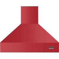
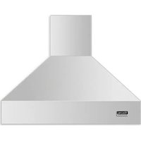
Download the instructions for your Basket in PDF format for free! Find your manual MVLWH636SS - VIKING and take your electronic device back in hand. On this page are published all the documents necessary for the use of your device. MVLWH636SS by VIKING.
USER MANUAL MVLWH636SS VIKING
Important safety Notice....4
Electrical & Installation requirements ....5
Electrical requirements 5
Before installing the hood 5
List of Materials....6
Parts supplied 6
Parts not supplied 6
Dimensions and Clearances....7
Ducting Options and Examples....8
Venting methods....8
Preparation 8
Installation....9
Preparation of the hood for installation: 9
Installation - Ducting version....10
Installation - Ductless (Recirculating) version....13
Description of the hood & Controls....16
Controls....16
User Servicing and Maintenance Instructions....17
Cleaning....17
Grease Filter 17
Replacing the light bulb....18
Charcoal Filter....18
APPROVED FOR RESIDENTIAL APPLIANCES
READ AND SAVE THESE INSTRUCTIONS
PLEASE READ ENTIRE INSTRUCTIONS BEFORE PROCEEDING.
INSTALLATION MUST COMPLY WITH ALL LOCAL CODES.
IMPORTANT: Save these Instructions for the Local Electrical Inspector's use.
INSTALLER: Please leave these Instructions with this unit for the owner.
OWNER: Please retain these instructions for future reference.
Safety Warning: Turn off power circuit at service panel and lock out panel, before wiring this appliance.
Requirement: 120 V AC, 60 Hz. 15 or 20 A Branch Circuit
READ AND SAVE THESE INSTRUCTIONS
Important safety Notice
CAUTION
FOR GENERAL VENTILATING USE ONLY. DO NOT USE TO EXHAUST HAZARDOUS OR EXPLOSIVE MATERIALS OR VAPOURS.
WARNING
TO REDUCE THE RISK OF FIRE, ELECTRIC SHOCK, OR INJURY TO PERSONS, OBSERVE THE FOLLOWING:
A. Use this unit only in the manner intended by the manufacturer. If you have questions, contact the manufacturer.
B. Before servicing or cleaning the unit, switch power off at service panel and lock service panel disconnecting means to prevent power from being switched on accidentally. When the service disconnecting means cannot be locked, securely fasten a prominent warning device, such as a tag, to the service panel.
C. Installation Work and Electrical Wiring Must Be Done By Qualified Person(s) In Accordance With All Applicable Codes & Standards, Including Fire-rated Construction.
D. Sufficient air is needed for proper combustion and exhausting of gases through the flue (Chimney) of fuel burning equipment to prevent back- drafting. Follow the heating equipment manufacturers guideline and safety standards such as those published by the National Fire Protection Association (NFPA), the American Society for Heating, Refrigeration and Air Conditioning Engineers (ASHRAE), and the local code authorities.
E. When cutting or drilling into wall or ceiling, do not damage electrical wiring and other hidden utilities.
F. Ducted systems must always be vented to the outdoors.
CAUTION
To reduce risk of fire and to properly exhaust air, be sure to duct air outside - do not vent exhaust air into spaces within walls, ceilings, attics, crawl spaces, or garages.
WARNING
TO REDUCE THE RISK OF FIRE, USE ONLY METAL DUCT WORK.
Install this hood in accordance with all requirements specified.
WARNING
To Reduce The Risk Of Fire Or Electric Shock, Do Not Use This Hood With Any External Solid State Speed Control Device.
WARNING
TO REDUCE THE RISK OF A RANGE TOP GREASE FIRE.
a) Never leave surface units unattended at high settings. Boilovers cause smoking and greasy spillovers that may ignite. Heat oils slowly on low or medium settings.
b) Always turn hood ON when cooking at high heat or when flambeing food (I.e. Crepes Suzette, Cherries Jubilee, Peppercorn Beef Flambe').
c) Clean ventilating fans frequently. Grease should not be allowed to accumulate on fan or filter.
d) Use proper pan size. Always use cookware appropriate for the size of the surface element.
WARNING
TO REDUCE THE RISK OF INJURY TO PERSONS, IN THE EVENT OF A RANGE TOP GREASE FIRE, OBSERVE THE FOLLOWING ^a :
a) SMOTHER FLAMES with a close-fitting lid, cookie sheet, or other metal tray, then turn off the gas burner or the electric element. BE CAREFUL TO PREVENT BURNS. If the flames do not go out immediately, EVACUATE AND CALL THE FIRE DEPARTMENT.
b) NEVER PICK UP A FLAMING PAN - you may be burned.
c) DO NOT USE WATER, including wet dishcloths or towels - a violent steam explosion will result.
d) Use an extinguisher ONLY if:
1) You know you have a class ABC extinguisher, and you already know how to operate it.
2) The fire is small and contained in the area where it started.
3) The fire department is being called.
4) You can fight the fire with your back to an exit.
^a Based on "Kitchen Firesafety Tips" published by NFPA.
OPERATION
a. Always leave safety grills and filters in place. Without these components, operating blowers could catch onto hair, fingers and loose clothing.
The manufacturer declines all responsibility in the event of failure to observe the instructions given here for installation, maintenance and suitable use of the product. The manufacturer further declines all responsibility for injury due to negligence and the warranty of the unit automatically expires due to improper maintenance.
Electrical & Installation requirements
Electrical requirements
IMPORTANT
Observe all governing codes and ordinances.
It is the customer's responsibility:
To contact a qualified electrical installer.
To assure that the electrical installation is adequate and in conformance with National Electrical Code, ANSI/NFPA 70 — latest edition*, or CSA Standards C22.1-94, Canadian Electrical Code, Part 1 and C22.2 No.0-M91 - latest edition** and all local codes and ordinances.
If codes permit and a separate ground wire is used, it is recommended that a qualified electrician determine that the ground path is adequate.
Do not ground to a gas pipe.
Check with a qualified electrician if you are not sure range hood is properly grounded.
Do not have a fuse in the neutral or ground circuit.
IMPORTANT
Save Installation Instructions for electrical inspector's use.
The range hood must be connected with copper wire only.
The range hood should be connected directly to the fused disconnect (Or circuit breaker) box through metal electrical conduit.
Wire sizes must conform to the requirements of the National Electrical Code ANSI/NFPA 70 — latest edition*, or CSA Standards C22.1-94, Canadian Electrical Code Part 1 and C22.2 No. 0-M91 - latest edition** and all local codes and ordinances.
A U.L.- or C.S.A.-listed conduit connector must be provided at each end of the power supply conduit (at the range hood and at the junction box).
Copies of the standards listed may be obtained from:
* National Fire Protection Association Batterymarch Park Quincy, Massachusetts 02269
** CSA International 8501 East Pleasant Valley Road Cleveland, Ohio 44131-5575
Before installing the hood
- For the most efficient air flow exhaust, use a straight run or as few elbows as possible.
CAUTION: Vent unit to outside of building, only.
-
At least two people are necessary for installation. Wear gloves to protect against sharp edges.
-
Fittings material is provided to secure the hood to most types of walls/ceilings, consult a Qualified Installer, check if they perfectly fit with your cabinet/wall.
-
Do not use flex ducting.
-
COLD WEATHER installations should have an additional backdraft damper installed to minimize backward cold air flow and a nonmetallic thermal break to minimize conduction of outside temperatures as part of the ductwork. The damper should be on the cold air side of the thermal break.
The break should be as close as possible to where the ducting enters the heated portion of the house.
- Make up air: Local building codes may require the use of Make-Up Air Systems when using Ducted Ventilation Systems greater than specified CFM of air movement.
The specified CFM varies from locale to locale. Consult your HVAC professional for specific requirements in your area.
List of Materials
Parts supplied
- Hood canopy with panel, lamps and motor already assembled.
- Duct Covers
- Grease filter assembly + fixing devices.
- Deflector (ductless version - 3 pieces to assemble)
- Hardware Packet:
Allen spanner x 1
Template
Use, Care and Installation guide
Hook x 2
Hook support bracket x 2
Duct Cover support bracket (3 pieces to assemble)
Lower support bracket
3,5x9,5 screws x 14
4x8 screws x 4 (to assemble Duct cover support bracket)
3,9x25 screws x 4 (to assemble hooks to support
brackets)
2,9x6,5 screws x 2 (to fix duct cover)
5 x 45 screws x 6 (for all fixing to rear wall)
Parts not supplied
- Duct, conduit and all tools required for installation.
- Ductless Recirculating Kit
To be used only in the Ductless (Recirculating) version
includes: charcoal filter, charcoal filter fixing devices.
Dimensions and Clearances
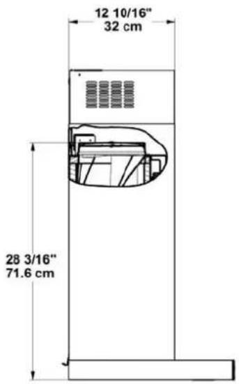
text_image
12 10/16" 32 cm 28 3/16" 71.6 cm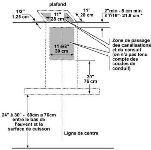
Ducting Options and Examples
Closely follow the instructions set out in this manual.
All responsibility, for any eventual inconveniences, damages or fires caused by not complying with the instructions in this manual, is declined.
Venting methods
The hood is equipped with a transition B for discharge of fumes to the outside (Ducting version).
Should it not be possible to discharge cooking fumes and vapour to the outside, the hood can be used in the Ductless (Recirculating) version. Attach a charcoal filter and the deflector F on the duct cover support bracket G. Fumes and vapours are recycled through the top grille H by means of a duct connected to the transition B and the transition mounted on the deflector F.
NOTE: For ductless (Recirculating) version only: purchase the Ductless Recirculating Kit. Minimum Duct Size (Ducting/Ductless version): 8" Round Pipe.
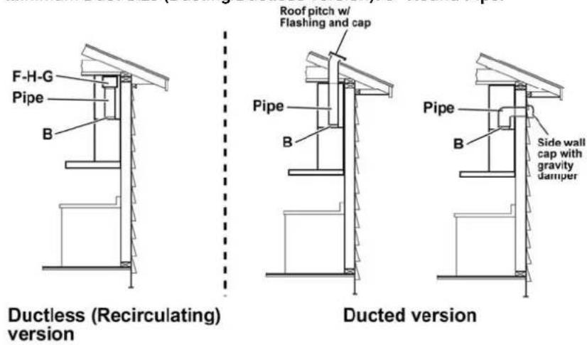
text_image
F-H-G Pipe B Roof pitch w/ Flashing and cap Pipe B Ductless (Recirculating) version Ducted version Pipe B Side wall cap with gravity damperPreparation
Do not cut a joist or stud unless absolutely necessary. If a joist or stud must be cut, then a supporting frame must be constructed.
Fittings material is provided to secure the hood to most types of walls/ceilings.
However, a qualified technician must verify suitability of the materials in accordance with the type of wall/ceiling.
Before making cutouts, make sure there is proper clearance within the ceiling or wall for exhaust vent.
Hood installation height above cooktop is the users preference. The lower the hood is above the cooktop, the more efficient the capturing of cooking odors, grease and smoke.
CAUTION: FOR GAS RANGES INSTALLATION: MOUNT THIS HOOD SO THAT THE BOTTOM EDGE IS AT 30" (76,2 CM) ABOVE THE COOKING SURFACE.
FOR ELECTRIC RANGES INSTALLATION: MOUNT THIS HOOD SO THAT THE BOTTOM EDGE IS NOT LESS THAN 24" (61 CM) AND NOT MORE THAT 30" (76,2 CM) ABOVE THE COOKING SURFACE.
HOUSEHOLD USE. PLEASE, READ INSTALLATION MANUAL FOR SPECIFIC APPLICATION.
Check your ceiling height and the hood height maximum before you select your hood.
Installation
Preparation of the hood for installation:
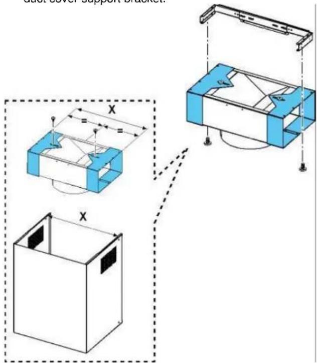
Assembling the duct cover support bracket (3 parts):
The three parts should be fixed with 4 screws, the support extension is adjustable and should correspond to the internal width of the upper duct cover.
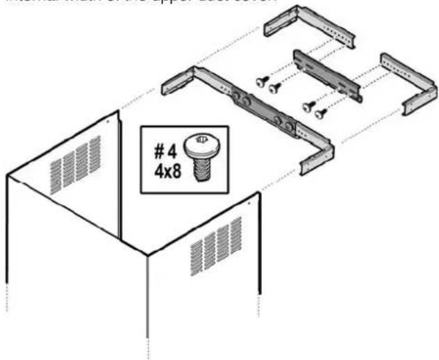
text_image
4
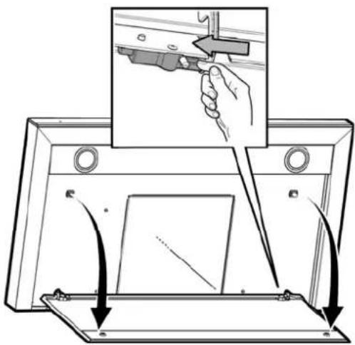
4x8To facilitate the installation it is recommended to remove the panel before installing the hood.
Attention! Keep both hands on the panel when disassembling or reassembling it into place to prevent it from falling and causing damage to persons or property.
Disassembly:
- Pull the panel (FRONT SIDE) firmly down,
- Push the small lever, located in the right side of the panel, to the left.
- Unhook it from the rear joints.

text_image
Diagram illustrating a mechanical assembly or inspection process with labeled components and directional arrows indicating movement.Assembling the hood's hooks:
a. Attach two brackets (one per side) to the upper side of the motor housing using 8 screws (4 per bracket).
b. Attach 2 hooks (one on each side) using 4 screws (2 on each hook).
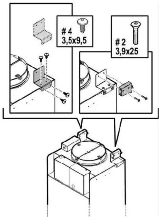
text_image
4
3,5x9,52
3,9x25Installation - Ducting version
- If possible, disconnect and move freestanding or slide-in range from cabinet opening to provide easier access to rear wall. Otherwise put a thick, protective covering over countertop, cooktop or range to protect from damage and debris. Select a flat surface for assembling the unit. Cover that surface with a protective covering and place all canopy hood parts and hardware in it.
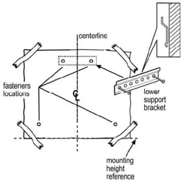
- Determine and mark the centerline on the wall where the canopy hood will be installed.
- Select a mounting height comfortable for the user and mark on wall.
- Tape template, matching center-line and hood bottom as shown in Figure below.
- Place the lower support bracket on the template making it coincide with the outlined rectangle, mark center of two fastener location and one lower fastener location then remove template.
text_image
centerline fasteners locations lower support bracket mounting height reference- Mark wall with horizontal line 1" above highest and 1" below lowest fastener location.
-
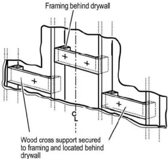
Find studs behind drywall by tapping wall or using a stud finder. Mark the center of the studs with a vertical line to the right and left of the marked fastener location.
-
Note: All fastener location must span the studs otherwise proceed as follows:
Cutout drywall along marked lines. Install wood blocking between studs and make sure it is flush with existing stud front. Make sure all mounting screws will anchor to added studs. Replace drywall and refinish.
text_image
Framing behind drywall Wood cross support secured to framing and located behind drywall- Determine and make all necessary cuts in the wall for the vent system. Install the vent system before the canopy hood. See „Venting methods“ and „Dimensions and clearance“ paragraphs.
- Determine the required height for the conduit and cut a 1-1/4" (3.2 cm) hole at this location.
Run wires through hole according the National Electrical Code or CSA Standards and local codes and ordinances.
There must be enough power supply cable from the fused disconnect (Or circuit breaker) box to make the connection in the hood's Junction box/es.
Use caulking to seal all openings.
Do Not turn on power until installation is completed.
-
Remark center line and hood bottom on same location as before and tape template on wall as in step 4 above.
-
Mount the lower support bracket with wood screws (Supplied in mounting hardware kit) on locations marked on template, then remove template.
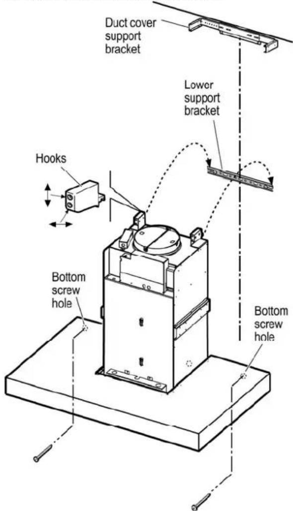
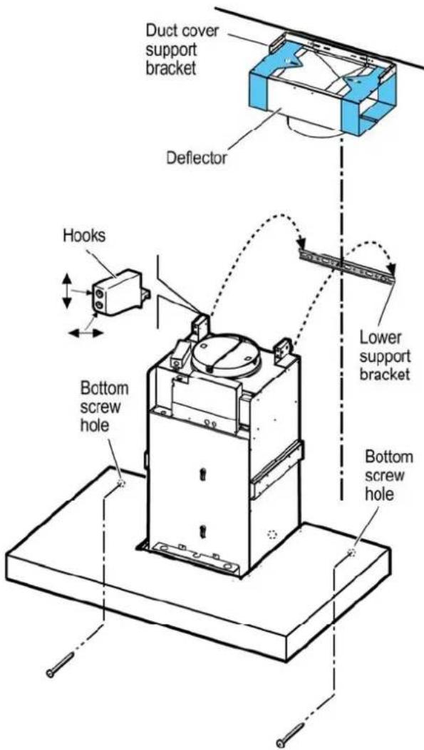
- Install duct cover support bracket to wall flush to ceiling with drywall anchors supplied (the duct cover support bracket should be installed about 1/8" (3mm) away from the ceiling).
- Hang hood with the 2 mounting hooks.
WARNING
Excessive Weight Hazard - Use two or more people to move and install range hood. Failure to do so can result in back or other injury.
- Level the appliance, using a carpenters level across bottom of hood with leveling screws in mounting hooks.
- Secure hood with 2 screws on bottom.
text_image
Duct cover support bracket Lower support bracket Hooks Bottom screw hole Bottom screw hole-
Connect ducting to transition. Seal with duct tape. Do not use duct smaller than the transition.
-
Electrical connection
WARNING
Electrical Shock Hazard
Warning: Turn off power circuit at the service panel before wiring this unit. 120 VAC, 15 or 20 Amp circuit required.
ELECTRICAL GROUNDING INSTRUCTIONS
THIS APPLIANCE IS FITTED WITH AN ELECTRICAL JUNCTION BOX WITH 3 WIRES, ONE OF WHICH (GREEN/YELLOW) SERVES TO GROUND THE APPLIANCE. TO PROTECT YOU AGAINST ELECTRIC SHOCK, THE GREEN AND YELLOW WIRE MUST BE CONNECTED TO THE GROUNDING WIRE IN YOUR HOME ELECTRICAL SYSTEM, AND IT MUST UNDER NO CIRCUMSTANCES BE CUT OR REMOVED.
Failure to do so can result in death or electrical shock.
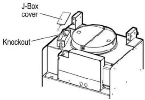
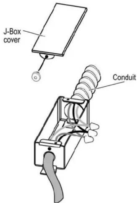
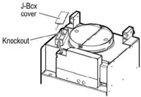
Remove the knockout and the Junction box cover and install the conduit connector (cULus listed) in junction box.
text_image
J-Box cover KnockoutRun 3 wires; black, white and green, according to the National Electrical Code and local codes and ordinances, in 1/2" conduit from service panel to junction box.
text_image
J-Box cover ConduitConnect black wire from service panel to black or red in junction box, white to white and green to green-yellow.
Close and secure junction box cover.
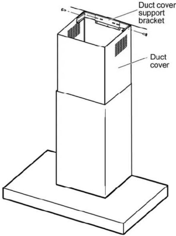
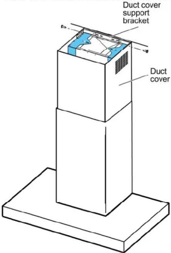
- Position the duct cover.
Fix the duct cover to the duct cover support bracket using 2 screws.
text_image
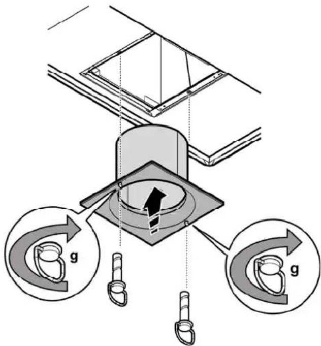
Duct cover support bracket Duct cover- Install grease filter assembly.
text_image
Technical diagram illustrating gear meshing process with labeled components and directional arrows-
Reinstall the panel.
-
Check all light bulbs to make sure they are secure in their sockets.
Turn power (On) in service panel. Check lights and blower operation.
If range hood does not operate:
- Check that the circuit breaker is not tripped or the house fuse blown.
- Disconnect power supply. Check that wiring is correct.
Installation - Ductless (Recirculating) version
- If possible, disconnect and move freestanding or slide-in range from cabinet opening to provide easier access to rear wall. Otherwise put a thick, protective covering over countertop, cooktop or range to protect from damage and debris. Select a flat surface for assembling the unit. Cover that surface with a protective covering and place all canopy hood parts and hardware in it.
- Determine and mark the centerline on the wall where the canopy hood will be installed.
- Select a mounting height comfortable for the user and mark on wall.
- Tape template, matching center-line and hood bottom as shown in Figure below.
- Place the lower support bracket on the template making it coincide with the outlined rectangle, mark center of two fastener location and one lower fastener location then remove template.

text_image
centerline fasteners locations lower support bracket mounting height reference- Mark wall with horizontal line 1" above highest and 1" below lowest fastener location.
-
Find studs behind drywall by tapping wall or using a stud finder. Mark the center of the studs with a vertical line to the right and left of the marked fastener location.
-
Note: All fastener location must span the studs otherwise proceed as follows:
Cutout drywall along marked lines. Install wood blocking between studs and make sure it is flush with existing stud front. Make sure all mounting screws will anchor to added studs. Replace drywall and refinish.

text_image
Framing behind drywall Wood cross support secured to framing and located behind drywall- Determine the required height for the conduit and cut a 1-1/4" (3.2 cm) hole at this location.
Run wires through hole according the National Electrical Code or CSA Standards and local codes and ordinances.
There must be enough power supply cable from the fused disconnect (Or circuit breaker) box to make the connection in the hood's Junction box/es.
Use caulking to seal all openings.
Do Not turn on power until installation is completed.
-
Remark center line and hood bottom on same location as before and tape template on wall as in step 4 above.
-
Mount the lower support bracket with wood screws (Supplied in mounting hardware kit) on locations marked on template, then remove template.
- Install duct cover support bracket to wall flush to ceiling with drywall anchors supplied (the duct cover support bracket should be installed about 1/8" (3mm) away from the ceiling).
- Install the deflector (Available as an extra kit) under the duct cover support bracket.
text_image
Cross-sectional Support Bracket X X- Hang hood with the 2 mounting hooks.
WARNING
Excessive Weight Hazard - Use two or more people to move and install range hood. Failure to do so can result in back or other injury.
- Level the appliance, using a carpenters level across bottom of hood with leveling screws in mounting hooks.
- Secure hood with 2 screws on bottom.
text_image
Duct cover support bracket Deflector Hooks Bottom screw hole Lower support bracket Bottom screw hole- Connect ducting to transition. Seal with duct tape. Do not use duct smaller than the transition.
Provide and install a duct to connect hood transition to deflector (The deflector is available as an extra kit).
18. Electrical connection
WARNING
Electrical Shock Hazard
Warning: Turn off power circuit at the service panel before wiring this unit. 120 VAC, 15 or 20 Amp circuit required.
ELECTRICAL GROUNDING INSTRUCTIONS
THIS APPLIANCE IS FITTED WITH AN ELECTRICAL JUNCTION BOX WITH 3 WIRES, ONE OF WHICH (GREEN/YELLOW) SERVES TO GROUND THE APPLIANCE. TO PROTECT YOU AGAINST ELECTRIC SHOCK, THE GREEN AND YELLOW WIRE MUST BE CONNECTED TO THE GROUNDING WIRE IN YOUR HOME ELECTRICAL SYSTEM, AND IT MUST UNDER NO CIRCUMSTANCES BE CUT OR REMOVED.
Failure to do so can result in death or electrical shock.
Remove the knockout and the Junction box cover and install the conduit connector (cULus listed) in junction box.
text_image
J-Box cover KnockoutRun 3 wires; black, white and green, according to the National Electrical Code and local codes and ordinances, in 1/2" conduit from service panel to junction box.

text_image
J-Box cover ConduitConnect black wire from service panel to black or red in junction box, white to white and green to green-yellow.
Close and secure junction box cover.
- Position the flue.
Fix the flue to the flue support bracket G using 2 screws.
text_image
Duct cover support bracket Duct cover-
Reinstall the panel.
-
Check all light bulbs to make sure they are secure in their sockets.
Turn power (On) in service panel.
Check lights and blower operation.
If range hood does not operate:
- Check that the circuit breaker is not tripped or the house fuse blown.
- Disconnect power supply. Check that wiring is correct.
Description of the hood & Controls
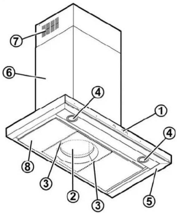
text_image
Technical diagram of a ceiling-mounted device with numbered components for identification1 Control panel
2 Grease filter (Behind the panel)
3 Grease filter release handle
4 Halogen lamp (Position and number of lamps may vary)
5 Hood canopy
6 Duct cover
7 Louver holes (Ductless configuration)
8. Panel
Controls
Description of control panel
To select the functions of the hood just touch the commands.

Light key ON/OFF

Intensive speed selection key (suction power) - duration 5 minutes - press again to return to previous setting.

High-speed selection key (suction power).

Medium-speed selection key (suction power) - when flashing it indicates the need to wash or replace the carbon filter. This signal is normally deactivated. To activate the alarm, disable the electronic by pressing the 0 button for 3 seconds.
Next, simultaneously press buttons 1 and 2 for 3 seconds; at first, only button 1 will flash, then both buttons 1 and 2 will flash to indicate activation. Repeat the procedure to deactivate the alarm; at first buttons 1 and 2 will flash and subsequently only button 1 to indicate deactivation.

Low-speed selection key (suction power) – when flashing it indicates the need to wash the fats filter.

Motor key OFF (stand by) – excludes the electronics – reset wash/replace filters signals.
MOTOR OFF
Press briefly to switch the motor off.
RESET FILTERS SIGNALS
In functioning mode, after carrying out filter maintenance, press the key until hearing the sound signal. The flashing LED 1 (grease filter) or 2 (carbon filter) stops flashing.
EXCLUDING THE ELECTRONICS
Press the key for 3 seconds. The hood command electronics will be excluded.
This function can be useful during the product cleaning operations.
Just repeat the operation to reinsert the electronics.
If the hood fails to operate correctly, briefly disconnect it from the mains power supply for almost 5 sec. by pulling out the plug. Then plug it in again and try once more before contacting the Technical Assistance Service.
User Servicing and Maintenance Instructions
Cleaning
Clean using ONLY the cloth dampened with neutral liquid detergent. DO NOT CLEAN WITH TOOLS OR INSTRUMENTS. Do not use abrasive products. DO NOT USE ALCOHOL!
Maintenance of the panel
Attention! Hold the panel with both hands when dismantling and re-mounting in position to avoid it falling and causing damage to people or things.
Dismantling:
- pull out firmly (LOWER SIDE) and rotate upwards.
- push to the left the small lever located on the right side of the panel..
- unhook it from the back hinges.
Cleaning:
Clean the suction panel with the same frequency as the fats filter using a cloth soaked in neutral liquid detergents.
Avoid the use of products containing abrasives. DO NOT USE ALCOHOLS.
Montage:
The panel must be hooked at the back and fixed in front fitted into the pins for the purpose on the surface of the hood.
Attention! always check that the panel is well fixed in its place.
text_image
Diagram illustrating a mechanical assembly or cleaning process with labeled components and directional arrows indicating movement.Grease Filter
Traps cooking grease particles.
The grease filter must be cleaned once a month using non aggressive detergents, either by hand or in the dishwasher, which must be set to a low temperature and a short cycle. When washed in a dishwasher, the grease filter may discolor slightly, but this does not affect its filtering capacity.
Remove the filter holder frame by turning the knobs (g) 90° that affix the chimney to the cooker hood.
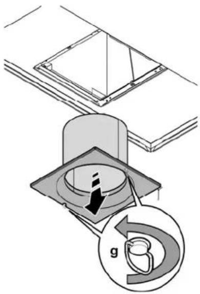
text_image
Technical diagram showing a mechanical assembly with a labeled component 'g' and directional arrows indicating motion or force.Replacing the light bulb
Disconnect the appliance from the electricity.
Warning! Prior to touching the light bulbs ensure they are cooled down. Replace the old light bulb with the one of the same type as specified in the feature label or near the light lamp on the hood.
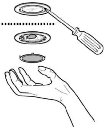
natural_image
Illustration of a hand holding a circular device with a tool, showing internal components (no text or symbols)- Using a flat head screwdriver or equivalent tool, carefully pry loose the light cover.
- Remove the damaged light and replace it with a new one (see the table below):
| Lamp | Power (W) | Socket | |
| 20 | G4 | ||
| Voltage (V) | Dimension (mm) | ||
| 12 | 10 (Diameter)22 (Light Center Length) | ||
| ILCOS D Code(according IEC 61231) | |||
| HSGST/C/UB-20-12-G4-10/22 | |||
- Reinstall the light cover. (it will snap shut).
If the lights do not work, make sure that the lamps are fitted properly into their housings before you call for technical assistance.
Charcoal Filter
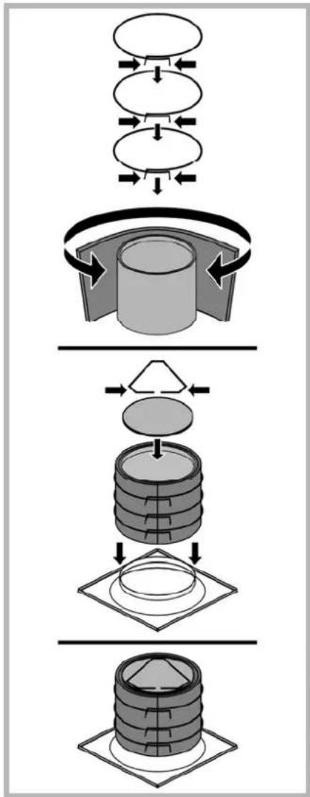
It absorbs unpleasant odors caused by cooking.
The charcoal filter can be washed once every two months (or when the filter saturation indication system – if envisaged on the model in possession – indicates this necessity) using hot water and a suitable detergent, or in a dishwasher at 65°C (if the dishwasher is used, select the full cycle function and leave dishes out).
Eliminate excess water without damaging the filter, then put it in the oven for 10 minutes at 100^ C to dry completely. Replace the mattress every 3 years and when the cloth is damaged.
Assembly
Place the mat around the grease filter and fix it in place using the devices provided.
Position the upper cap and fix it in place using the fixing pin.
To disassemble, perform the steps in the reverse order.
flowchart
graph TD
    A["Raw Material Input"] --> B["Coating"]
    B --> C["Assembly"]
    C --> D["Packaging"]
    D --> E["Final Product Output"]
French
Sommaire
* La National Fire Protection Association, Batterymarch Park Quincy, Massachusetts, 02269
** La CSA International, 8501 East Pleasant Valley Road, Cleveland, Ohio, 44131-5575
text_image
Diagram illustrating a mechanical assembly or cleaning process with labeled components and directional arrows indicating movement.text_image
Technical diagram illustrating gear meshing process with labeled components and directional arrowstext_image
Technical diagram showing 3D mechanical assembly with labeled dimensions X and coordinate axes, including a dashed box view.text_image
Technical diagram of a ceiling-mounted device with numbered components for identificationtext_image
Diagram illustrating a mechanical assembly or cleaning process with labeled components and directional arrows indicating movement.Filtre à graisse
natural_image
Technical diagram showing a mechanical assembly with a component labeled 'g' and a magnified inset (no text or symbols present)natural_image
Illustration of a hand holding a circular device with a tool, showing internal components (no text or symbols)flowchart
graph TD
    A["Top Box"] --> B["Top Box with Inner Circle"]
    B --> C["Top Box with Outer Circle"]
    C --> D["Cylinder with Inner Ring"]
    D --> E["Layered Storage"]
    E --> F["Layered Storage with Inner Ring"]
    F --> G["Layered Storage with Outer Ring"]
Spanish
Contenido
* National Fire Protection Association Batterymarch Park Quincy, Massachusetts 02269
** CSA International 8501 East Pleasant Valley Road Cleveland, Ohio 44131-5575