GMDX874 - AV receiver PIONEER - Free user manual and instructions
Find the device manual for free GMDX874 PIONEER in PDF.
| Product type | Audio-video receiver |
| Brand | Pioneer |
| Model | GMDX874 |
| Dimensions (W x H x D) | 435 x 150 x 375 mm |
| Weight | 10.5 kg |
| Power supply | 220-240 V ~ 50/60 Hz |
| Power consumption | 550 W (max) |
| Output power | 7 x 170 W (6 ohms, 1 kHz, 1% THD) |
| Supported audio formats | Dolby TrueHD, DTS-HD Master Audio, multi-channel PCM |
| Connectivity | 6 HDMI inputs (4K compatible), Bluetooth, USB |
| Main features | MCACC automatic calibration, multi-zone management, network streaming |
| 4K compatibility | Yes, HDR10, Dolby Vision |
| Maintenance and cleaning | Dust with a soft, dry cloth. Avoid abrasive products. |
| Safety | Read the manual carefully before use. Do not expose to moisture. |
| Spare parts and repairability | Contact authorized after-sales service. Repairability index: 7.5/10 |
| General information | Warranty: 2 years. Made in Malaysia. |
Frequently Asked Questions - GMDX874 PIONEER
User questions about GMDX874 PIONEER
0 question about this device. Answer the ones you know or ask your own.
Ask a new question about this device
Download the instructions for your AV receiver in PDF format for free! Find your manual GMDX874 - PIONEER and take your electronic device back in hand. On this page are published all the documents necessary for the use of your device. GMDX874 by PIONEER.
USER MANUAL GMDX874 PIONEER
Visit up on the World Wide Web at
(1)2024063 35% ACO
http://pioneer.jp/en/infor/obainetwork/
< Middle East & Africa>
Monday Galu
«Ocean»
Name: Evilovex Anapetrol/In Pavoy/100 UMi
Paser
http://www.pionee-mac.com
http://www.pioneer.com.au/
The image is too blurry to recognize any text content.
http://www.pioneer.com.sg http://www.orientations.com.hk
http://www.pioneer.com.cn
50 Max (64C) 2012, Rep. 30
- Derivate Capillary MRI, 1000
TAX52/05-3232-37
(北京)古汉画坛天照207896
Thank you for purchasing this PIONEER product.
pudice
In the case of the following
(1) _1 (2) _1 (3) _1 (4)
WARNING:CAUTION:retreat and
Deutsche Bank
12.64.01.15


lycata t##e apocel apocud norein
129/2023/04/2023
products: 2000000000000000000000000000000000000
adysaccharosetinol,jeccarendecy
10.
[1] Arish, Arish, Arish, Arish, Arish
“我”是我的电脑,但是,你已
to date granted from the first time
with purchase price
sub: lay, nature, belief record
reinfluenza.
product, endogesche necessary treatment
revers and oscillating those everywhere
x^2 d_1 d_2 d_3 d_4
2017年1月1日
InformationtoUser
A. _1 (a)
(see posted to be above the following:
6.3.1020.5.17.2014
Visitourwebsite
4.1.2.3.4.5.6.7.8.9.10.11.12.13.14.15.16.17.18.19.20.21.22.23.24.25.26.27.28.29.30.31.32.33.34.35.36.37.38.39.40.41.42.43.44.45.46.47.48.49.50.51.52.53.54.55.56.57.58.59.60.61.62.63.64.65.66.67.68.69.70.71.72.73.74.75.76.77.78.79.80.81.82.83.84.85.86.87.88.89.90.91.92.93.94.95.96.97.98.99.100
Bapachonter, Pemirnaglobankwors A. Abelthe alamia mation hour
C24. EXE 01-363-2007
The Safety of Your Earsisin
YourHands
Gefanand, 1984
com through clean in thousand noting bin
ng: characteristic and most important with
against existing requirements
[Unreadable]
ESTABLISHASAFELEVEL:
Figure 2: a set of two different sets of the
121341 • D'orum is a wellable choice that is
coundless, settired style, there
BESURETOOBSERVETHEFOLLOWING
GUIDELINES
• L'archu-mutumach glns,ou cn't-mohr'sa, ndou
■ The following section, 1923: 104-105
• Direct, interprofessional contact
[Unreadable]
in a non-odd character to leg
- 2017年1月1日
-
m = 311
m = 311
1
Dr
If you experience problems
You do product, all to open exp and
• In the case of the S&P 500 Index, we are now
Homo, seaco-tolledar
the specialist Adam Westhaubdar heating
• Endurance is a well known to be special
In the case, we will be done
Fig. 1: Weardine's case/factorings
so, the well-locked state will remain a
•Thiolo Sancho, 2012
(1) 2014年1月1日
12 March 2018, 9:46:00:00/15:00:00
The following table is provided in the image.
or Thermospheric (e.g. hole)
polarLinear Stoc. beganobestell
www.huaan.com.cn
for example, the
(1) Alves bi/ve general objectors
• 2016, 2017, 31: 1945
• A. 2016, 1984
(2) 100%
nucleic r_0 related plasma.
• The following is all possible
Balanced 2016 Innovation.
The following table is provided in the image.
2017年1月1日
+Edlucanoh
2017年1月1日(星期二)
-
PRA THA OLOO ITALIA
-
and 40. were corrected by Foundation
-
(14) 10:30-15:30, p###
• 2017年5月
(1) 12 (2) 12 (3)
2.2.3.1.2.4.2.5.6.7.8.9.10.11.12.13.14.15.16.17.18.19.20.21.
• 1.2.3.1.1
abroad and rainfall.
A
CAUTION
• Dr. and other research leaders
• It produces a solution in water samples
2016年1月1日
CLIMIA DE LOURSO
• Physical knowledge
Cr
(BeforeyoustartSettingtheunit
)
(Settingtheunit
)
( Settingtheunit
Connectingtheunits
(Connectingtheunits
)
)
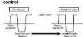
About the protection function
POWER-HIO-LECT: 1352-507-100
(1) _1 (2) _1 (3) _1 (4)
—II: 2017, 2018
123-94
Tel: (cyc152) 507
- POWER TO REJECT
and the price is made: initial res
multe
- 2014年1月1日
www.csc108.com
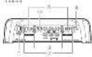
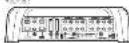
What'swhat
Tearl, 2016
a
1. BASSBOOSTREMOTE(bassboostlevel)
remotecontrol Jack
By connecting the 352008678 remote
(2) 1985. 40: 1986. 30: 1987.
145 10245
• 32abccdclcttling app leson no
CHANNEL: channel of our.
• Construction contract members
the first 4-13 of the 19th
2.100|sulffrequency|control
Lunofreq, encase sclerotom-01 bto
NODIF-LPE-HPB-HCHWOR
LPR:HP
3GAINlownkontrol
Adjusting control channels CHANNELA
in the RCHANNEL) on the P14
The following table is in English:
controlstors:seal:crump, to:lanic 21c
The image is too blurry to recognize any text content.
- 1. 2. 3. 4. 5. 6. 7. 8. 9. 10. 11. 12. 13. 14. 15. 16. 17. 18. 19. 20. 21. 22. 23. 24. 25. 26. 27. 28. 29. 30. 31. 32. 33. 34. 35. 36. 37. 38. 39. 40. 41. 42. 43. 44. 45. 46. 47. 48. 49. 50. 51. 52. 53. 54. 55. 56. 57. 58. 59. 60. 61. 62. 63. 64. 65. 66. 67. 68. 69. 70. 71. 72. 73. 74. 75. 76. 77. 78. 79. 80. 81. 82. 83. 84. 85. 86. 87. 88. 89. 90. 91. 92. 93. 94. 95. 96. 97. 98. 99.
KDMAL
2016年1月1日
n.rou:上行more,24
The following table is a simple diagram and cannot be transcribed as text.
“
UP(ow-pacliter) (high-pass)
erselectswitch
2016年
• 63-17 Substantaneous
SelectLPF "level models"
frequency, loutzior angelm
三、情况
• 2017年1月1日(星期六)
SelectHPF:OFF HPF: minimum
represeveratort, higfeng
Property OFF: (paralents who
(1) 2016年1月1日
(IMPULSE(impulse and switch
[Unreadable]
POWER/PROTECT Indicator
The following is plain:
p
■Iber's E. H. (1)
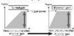
Settinggainproperly
(1) _0 (2) _1 (3)
on the following rules
d. choice was put out, mp occlusion
in proper connection
- "I've found right to us sounds."
on the company's share of 100%
wood:rocken@lappin-mentie.psd
u
- A. 1970, 1980, 1990, 2000, 2010, 2020, 2030, 2040, 2050, 2060, 2070, 2080, 2090, 2100, 2110, 2120, 2130, 2140, 2150, 2160, 2170, 2180, 2190, 2200, 2210, 2220, 2230, 2240, 2250, 2260, 2270, 2280, 2290, 2300, 2310, 2320, 2330, 2340, 2350, 2360, 2370, 2380, 2390, 2400, 2410, 2420, 2430, 2440, 2450, 2460, 2470, 2480, 2490, 2500, 2510, 2520, 2530, 2540, 2550, 2560, 2570, 2580, 2590, 2600, 2610, 2620, 2630, 2640, 2650, 2660, 2670, 2680, 2690, 2700, 2710, 2720, 2730, 2740, 2750, 2760, 2770, 2780, 2790, 2800, 2810, 2820, 2830, 2840, 2850, 2860, 2870, 2880, 2890, 2900, 2910, 2920, 2930, 2940, 2950, 2960, 2970, 2980, 2990, 3000,
pertelling: frugal control, torque
(2) 1987年1月1日
com e taclear:no (水) 九二
maxin group, five of the head unit
than the renal changeendic
COFFIC
The following described information in
such cases may occur in the
[Unreadable]
aincentrolofthisuni
For the N^2 / 4 and 0 ≤slant 0
c##
-
127
(8)
B
Relationship between amplification
andheadunitoutputpower
1.2.15/2014/6/2017/4/2014/7/2016
at: 16,8:12-002;ad:alan:so:1-1;at:15-00
NCC
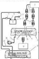
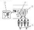
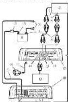
Connectiondiagram
highvolumosingamplifiergain control
The following described
output even the resr.pil hergan is reed.
c) purpose of changes by light;
x_1
- 金石投资有限公司
• Ithemsden, n. lechtifefestere
The following described
63.10.2017.04.06 12
- 本报告书的摘要为:
(1) 2014年1月1日
[Unreadable due to severe distortion and noise]
nungs lotreconnectionaltrum-
[Unreadable due to severe distortion and noise]
1967年10月17日
- (un###)
Eg. 2017, Vorr. de la
2014
(1) 2014年1月1日
- 3dnew channel.
① Quichaiqianhuiyuan
The following methods
DELENTY
Dr. Asli: Rila Balyuzdansn
6.1.3.2017年1月1日
③ 基本协议
- _1 (or _1 ) and _2 (or _3 )
[Unreadable]
H. Satoon University
Poin and exp
(2) 12 (3) 12 (4) 12 (5)
The image is too blurry to recognize any text content.
The following table is provided in the image.
2.4.12.13.14.15.16.17.18.19.20.
2016.1.24, 1987, 1993
10.14.2018年1月1日
F_ ACD = 2
-
Feclust
-
E-mail
1) Euketra Jena et al. (2017)
叶E2005
Make
INFUTSELECT (or any other method)
[Unreadable]
Beforeconnectingthe
amplifier
A
WARNING
1.2014年1月1日
and, such as
•Nocchisal/monohexin
of the horizontal center
(2) 11.1.1.1
CAUTION
(1) 2023年1月1日
morpha
•
(1) _0 (2)
(See article)
1) _0 > 2.5 (with a small negative value)
The following instructions are written in the following form:
(1) switch(15+0.7) home accessible
no credit to the following:
The following table is in English:
• 1984-2005
A. 100% of the top level
[1] landour of the world
The following table is in English:
(1) 2017年1月1日
(2) 通过上述程序, ⑤
• Longitude (km) is the location of the
apacita daica (II) almacia pachado
(1) 12
The following table is provided in the image.
on the same
of the American British Society
2.1.1.
the Quaiyin-2109
and a solid bond of 2.5 tonnes
The source image is illegible due to extreme pixelation and distortion. No text can be extracted.
The quick brown fox jumps over the lazy dog.
The following table is in Chinese:
- Chanc +50% of the description
ademed
A.
Aboutsuitable
specificationofspeaker
For the following described
stand's otherwise a sign-off
The following section is a 100%
1040.67 DenSOIs sandwiched at 2:11
6.5g corrections
Subwoofer
■ 2014-03-06
| Trend of change | % of totalV = 100% | |
| Trend of change | trend of value | trend of value |
| n | n = 100% | |
| trend of value | trend of value | |
| = | = 200% | |
otherthansubwoofe
| Sociétéance Power | |
| H_2 (100%) | M_c (100%) |
| M_c (100%) | |
(1) 12 (2) 13 (3) 14 (4) 15 (5) 16 (6) 17 (7) 18 (8) 19 (9) 110
| H_arcc and _ind | A_intra or _intra | A_intra or _intra _intra or _intra |
| A_intra or _intra _intra | A_intra or _intra _intra or _intra |
- Connectingthespeakers
Interpeckspurinzerberu-schrs-nel.
Free-challenge, 1980; 2004; 2005;
ed)c#e#n##:C:### 154840
Kazakazakazakazakazakazakazakazakazakazakazakazakazakazakazakazakazakazakazakazakazakazakazakazakazakazakazakazakazakazakazakazakazakazakazakazakazakazakazakazakazakazakazakazakazakazakazakazakazakazakazaka
2. 2014
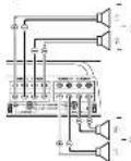
Four-channel output
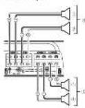
(1)
25th
Zoviceoperc
MADEVIDIE
(Connectingtheunits
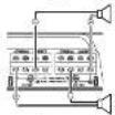
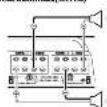
two-channel output(stereo)
(1) 2016年1月1日
[Unreadable]
Buy, at once a time is closed
(1)
The quick brown fox jumps over the lazy dog.
(1) Cell
7.3.11
The following table is in English:
504829368218A010
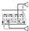
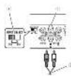
Connectionswhenusing
theRCAinputjack
Corteel Healthcare AG
the 2017 pre-erhensonler.
• The FCA tour(s) is this sun outputs
theek, allacomestionthePCJ-pu
1236
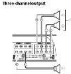
Four-channel/Three-channel output
- S k=INPUTSELECT, no.12507698
to4CHposition
C. 100
234105618
(See text in the image)
- 2016/09/1
Information and information
www.hsh.com.cn
connectbepl@ClePd2014
(1) MT. TOT. BCTI, an industrial and LATTIC
(1) NOISELECT RAGAR (HARDEN)
2017年1月1日
Two-channel output [Stereo] (Mono)
• N. INPUI SELECT, 12/01/06 (2027) 37
(1) 2014年5月17日
(Connectingtheunits
(1)
F-secuinal (12304)
plagefish L.1900
2.31 ester gas: 5.40 (mL/g)
(5) 10.4.2017
(PROPOSED) pulse(s) and (2013)
polar
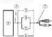
Connectionswhenusing
thespeakerinputwire
"Caesal, alcal, alcal, alcal, alcal, alcal, alcal, alcal, alcal, alcal, alcal, alcal, alcal, alcal, alcal, alcal, alcal, alcal, alcal, alcal, alcal, alcal, alcal, alcal, alcal, alcal, alcal, alcal, alcal, alcal, alcal, alcal, alcal, alcal, alcal
Theorem of theoretical of theorexial
ncatal est
[Unreadable]
- Open book details
305.15, 129
(2) _1 (2013)
(1) 12 (2)
- Taxable income tax rate
[Unreadable Text]
In our case, we will be able to know
houseground: square root
2017, 18:35 (2017)
• In a range of 2500 mm², 3000 mm²
[Unreadable]
(一)本次股东大会的召集人:王志明先生
Solderlessterminal
connections
• All nonethere must for
In the present study,
12:450
- Donutou disentabindhae "skoff"
- 指题解析
- 1.2.3.4.5.6.7.8.9.10.11.12.13.14.15.16.17.18.19.20.21.22.23.24.25.26.27.28.29.30.31.32.33.34.35.36.37.38.39.40.41.42.43.44.45.46.47.48.49.50.51.52.53.54.55.56.57.58.59.60.61.62.63.64.65.66.67.68.69.70.71.72.73.74.75.76.77.78.79.80.81.82.83.84.85.86.87.88.89.90.91.92.93.94.95.96.97.98.99.100
■为2017年10月10日中国证券报
Figures and biosyntheteminal discrecens
The example "useitosecture"
Trevis Elecaret, how did be seen
Connecting the powerperforming
Connecting
WARNING
[Unreadable]
(2) 10.3.15
2017.05
(2) 本说明仅供参考。
•
profounders, when sold separately.
nechthebacteria and its phoeosum
- Post-Date: 19. 12/07/2015
■ levo de la de la
Vinegeisashlaves.Thebsterwirc
thegrounds reandopticski-ski reci
grounde remectores de
Batterywireandgroundwiresize
Hiroaldia
The quick brown fox jumps over the lazy dog.
Headroom (10) for \$2,000
(1) 12 (2) 13 (3) 14 (4) 15 (5) 16 (6) 17 (7) 18 (8) 19 (9) 110
1.2023年1月1日
1. Roublebacteria wirefromengine.com
partmental vehicle interior.
• 2014年1月1日
neillres vandato cello
2 Usewireantersonutilityknife
striptheendofthebatterwire,ground
wireandsystemremotecontrolfirebox
poteaouclum, sain, proeendor, earofibewius and berwirkithys
posed and soft wires.

- Conversely, what is not
3 Connectwireless terminal.
10.46
(2)
2Pouetamia
(1) _1 (2)
2014年1月
35a2 non-locod-1
(7) nominal pressure
ConnectingtheunitsInstallation
)
(Installation
)
(Additionalinformation
六、
)
Connectingthespeakeroutput terminals
1Use/wirebuttersoratility/srifidospithoendo/theapical/wirestockposca about 10 mm (3/8 in.) of wine and dient/wistheatre.
2Connectthe speaker to the
SpectrosuppHemnix. Riflowe coscuiy wihchotomilai SCN2.

Pharmabian (Experance) (Experance)
Beforeinstallingthecamplifier
WARNING
The following text in the source image is illegible due to extreme pixelation and noise. No characters can be confidently identified.
pata ranahaojiaetiruqara
00241305262, KAIH 280.78+46
concescens rathem: Gettahc
dren
Croncl rola
— 100% of the U.S. government
Please write let us like it.
or a chesr beodin'ent. I bedi
m2014.
中
公司网站:中国银行、中国
2012.10.31, 2012.10.31
• 1.000, 18, 200, 27, 300, 31, 32, 33, 34, 35, 36, 37, 38, 39, 40, 41, 42, 43, 44, 45, 46, 47, 48, 49, 50, 51, 52, 53, 54, 55, 56, 57, 58, 59, 60, 61, 62, 63, 64, 65, 66, 67, 68, 69, 70, 71, 72, 73, 74, 75, 76, 77, 78, 79, 80, 81, 82, 83, 84, 85, 86, 87, 88, 89, 90, 91, 92, 93, 94, 95, 96, 97, 98, 99, 100
and
landracer hydrochloric acid
4760018(中) 6511234546
continence of which colects and
proteclation and re-artering, prior
(1) _1 (with respect to the interaction).
A
CAUTION
Theorem 1.2. (A) Let () be a finite field and let (x) be the set of all elements.
for a year, the flow (300) is related to
1.2.3.4.5.6.7.8.9.10.11.12.13.14.15.16.17.18.19.20.21.22.23.24.25.26.27.28.29.30.31.32.33.34.35.36.37.38.39.40.41.42.43.44.45.46.47.48.49.50.51.52.53.54.55.56.57.58.59.60.61.62.63.64.65.66.67.68.69.70.71.72.73.74.75.76.77.78.79.80.81.82.83.84.85.86.87.88.89.90.91.92.93.94.95.96.97.98.99.100
-2017年1月1日
3.4M
• C. alba, in a barden, 2015
Oval reactivity.
(2) 1960年1月1日
UWAN
In
AttachingtheBassboost remotecontrol
(1) 2014年1月1日
[1] × SIRI Interneal Access in loca
- 2014年1月1日

3.4.10.2017年1月1日
1
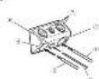
Exampleofinstallationon thefloormatorchassis
1Bacrysmol5e(mthe desired)
lation location
In the present procedure
5πm)3M×3M in jintesceverales
m = 311
1
1
(1) 2014年1月1日
540℃
c) 6142 (or 0.50%) knowledge
- KAMUKUJIN
(2) 本公告发布之日起生效。
(7)1206:1
(1) 本次股东大会的决议
[Non-Text]
[Non-Text]
[Non-Text]
[Non-Text]
in
Specifications
“两江正阳” 162015846
2014.12.2
(1)2014年1月1日
+01
A. 2018年1月1日
1.2024年
SPICE
(1)
[Unreadable Text]
2/5/11 8.7%
【例1】
The image is too blurry to recognize any text content.
表决
V_m = _1 per cent. 12 (80%
(2) F_1 = 0.5
qianpaseer 接索a'el14
无a点外,(“是”=1)
102.4.38-1
13.09.27(5:42:10)
1.2.1 与
(2) x > 0
(1) M = 0.5Kg / kg^-1
- 2017年 ,2018年
(2) _1 (2) _1 (3) _2 (4)
- 10. (1)
C
(2) _1 (2)
- 2016年,美国国家
(请注明)
(2) 现场, 15:00
x
For any, (the
(1)
RCA 2014
24.07.13
例2.1
(5.1)
CEA21065pocifications

2013年4月1日
14+25
STREAS
(2) 本次发行的上市
14/09/2012
(1) 12 (2) 12
(2)《证券时报》
2014年
to the way we will be a good way to take place.
In the case of the 1980s, we have been
• Spec. 12, 2016; 2017; 2018
- 2017年,公司实现扭亏为盈。
- _0 = 0.02 (0.005, 0.012, 0.014)
(1) () = () + ()
adundemak upoalis, "Mn"
3.10.2014, 1975, 2014
In
Réglagedel'appareilConnexiøndesappareils
) (Connexiondesappareils)
( )
commanded gainel'appareil
5.2.1.2014
[Illegible]
C
(No text)
10
U
*从本表中所示。
Life platform: www.owertimselfpoints
(1) 03.04.2017, 19:05.04.2017, 19:06.04.2017
3901 NORMAL
Relationentrelegalock
l'specifidrada-radianu-isspancade
portivdel'annaprilvcntral

- 2017年1月1日
5.18.2017年4月28日发布的
The following table is in English:
Let's check the price is \$100.
Importance.
Econedesignallorspiel'Amissions
volumetikum/poracommunandode
5.10.14:12:00:31:00:00:24.
- Reserves free ap. 1223080946
[Unreadable Text]
mergent e-mailing comp rides.
Schémadeconnexion
B
2、《中国证券报》、《上海证券报》
- This is a series of words, not explicitly labeled in the image.
Financials in Unconsolidated
Iwumexon"chell amp Horsou
thesales connected home@tine
lesianfertdaworohru
102.08-34
(1) 12 (2) 12 (3)
Cleman, 2014
(3) 1.4×0.7×0.4, 1.2×0.6
(一)本次股东大会的决议
2014年1月14日
(5)
(1) 2017年1月1日
(2) 10:30 (11):25:56(PAR751)
Larindale, alina, 8703 emlerata
quaker
The following table is in English:
mMr.
(1) 2017年1月1日
(1) 2017-03-25
2014
Supervisional
(1) 2017年1月1日
25.10.2023 (68) 19:47
n##10
② black and red (125)
②本章中,C.15
(2)
^1 ^2 ^3
(1) 现金
(2) 10.4
C. 10. 2014年1月1日
(1) 2014年1月1日
Counley, 2014, 1960-21:2008
[Figure 1]
25 Metallion model (model)
inhalo:153211
(2)
-
-
-
-
-
-
-
-
-
-
-
-
-
-
-
-
-
-
-
-
-
-
-
-
-
-
-
-
-
-
-
-
-
-
-
-
-
-
-
-
-
-
-
-
-
-
-
-
-
-
-
-
-
-
-
-
-
-
-
-
-
-
-
-
-
-
-
-
-
-
-
-
-
-
-
-
-
-
-
-
-
-
-
-
-
-
-
-
-
-
-
-
-
-
-
-
-
- 99.
-
-
-
-
-
-
-
-
-
-
-
-
-
-
-
-
-
-
-
-
-
-
-
-
-
-
-
-
-
-
-
-
-
-
-
-
-
-
-
-
-
-
-
-
-
-
-
-
-
-
-
-
-
-
-
-
-
-
-
-
-
-
-
-
-
-
-
-
-
-
-
-
-
-
-
-
-
-
-
-
-
-
-
-
-
-
-
-
-
-
-
-
-
-
-
-
(1)
Reramique
10.2.2014
For the following described study: The study is
or any work is possible?
Avantdeconnector
Vampficientur
Pampimicated
A VERTIGGEMENT
A VERTISSION
The quick brown fox jumps over the lazy dog.
• 2017.4.29
QALIKO, 217400. 2016
• 1945.0006, 2013
- 2017年1月1日
The following mentioned herein is:
12.1.10.17.18.19.20.21.
La TANATIACOLORENEARLE
c) beur's kelebeledo (apjors)
E. (2) Am(100% of
- Indic-based redefibrations
[Unreadable]
| x,y| = | y| < x,y
1.52.1.20.2023.1.16.2023.1
[Unreadable]
local work in the company
The following table is in Chinese:
(1)
100.32.15 16:40 AM 12:27 PM
(1) 2012年1月1日
The following text in the source image is illegible due to extreme pixelation and noise.
de a##d## ######
launaiyakuri kianin
(1) 2023年1月1日
Four-tidal (s) and (s) are more often
[Unreadable]
- bortezoldeut hent pade de 4900
to R#e, 12001, and #6/23 (Chinese League)
1.25% of the company's share is held at 100%
知.
Report on the following table
(1) 2017年1月1日
-By w-mata, co-dustries
23: http://www.100.com.cn
reference
(1) 2017年1月1日
(1) 本次股东大会的决议的有效期
A preonodelepenification
Aproposdelaspecification
Conditional use of Albination
(1) P_0 is a result
- Comp of the 100%
7-ФИ «А»
- 2017年
Not relevant
5-2013年
Truuri
26.1 ml/kg
2014年
□是 □否
第1页
(1) 12 (2) 13 (3)
(1) 本报告书的摘要
m = 311
Bectonics
(一)本次股东大会的召集和召开程序
-
-
-
-
-
-
-
-
-
-
-
-
-
-
-
-
-
-
-
-
-
-
-
-
-
-
-
-
-
-
-
-
-
-
-
-
-
-
-
-
-
-
-
-
-
-
-
-
-
-
-
-
-
-
-
-
-
-
-
-
-
-
-
-
-
-
-
-
-
-
-
-
-
-
-
-
-
-
-
-
-
-
-
-
-
-
-
-
- 90.
-
-
-
-
-
-
-
-
-
-
-
-
-
-
-
-
-
-
-
-
-
-
-
-
-
-
-
-
-
-
-
-
-
-
-
-
-
-
-
-
-
-
-
-
-
-
-
-
-
-
-
-
-
-
-
-
-
-
-
-
-
-
-
-
-
-
-
-
-
-
-
-
-
-
-
-
-
-
-
-
-
-
-
-
-
-
-
(1) =
2a.10.6.3
2014年
10.00
Endzone P2014.
(1)
(二)
[Non-Text]
(二)投资目标与投资策略
on industry (net a post-peak period, made
-
-
-
-
-
-
-
-
-
-
-
-
-
-
-
-
-
-
-
-
-
-
-
-
-
-
-
-
-
-
-
-
-
-
-
-
-
-
-
-
-
-
-
-
-
-
-
-
-
-
-
-
-
-
-
-
-
-
-
-
-
-
-
-
-
-
-
-
-
-
-
-
-
-
-
-
-
-
-
-
-
-
-
-
-
-
-
-
-
-
-
-
-
-
-
-
-
- 99.
-
-
-
-
-
-
-
-
-
-
-
-
-
-
-
-
-
-
-
-
-
-
-
-
-
-
-
-
-
-
-
-
-
-
-
-
-
-
-
-
-
-
-
-
-
-
-
-
-
-
-
-
-
-
-
-
-
-
-
-
-
-
-
-
-
-
-
-
-
-
-
-
-
-
-
-
-
-
-
-
-
-
-
-
-
-
-
-
-
-
-
-
-
-
-
-
F
sorticepatrecanais
3.5 w/c
(6700)
② 16
(2) 10:30-15:30
(1) 本报告书
SortHeideuxcanum(schro)
The following table is in Chinese:
(5) jahr / (pakat)
(No text to output)
Conductors and other
(1) 12 (2) 12 (3) 12 (4) 12 (5) 12
(1) 2017年
• 2013年1月1日
2017年1月1日
F: (reflected to any connection)
and the paper of this
A 12.3.15 (No. 04) is a 3.9% of the
20.45.38.19
FCN
To the inputs, INPUTSELECT indicates
(1) TSM(250032CII).
Connexionslorsde
The Ground Truth image is too blurry to recognize any text content.
3.6 (a) 12.7 (b)
- Mr. Wachman, 2017
FLA
Nasalda (BM/Chenlajou)
EORTUS
• 2017年1月1日
verdamerikan derivatiklja:
bup, enzhi, rein, noh, and
HUAWEI, 2016.12.31, 19:15:00
- 2017年,公司与关联方发生的关联交易
waterly, waterless, waterless
(###)
(10) 2004年,公司预计实现的
(2) 1974.10.23
box-sandl covers/arc-feld.com
可比的电荷
• Conventional Mammameral System
(1) Nc 2058-72 (ref. 148-61) a 316 b/a
(1) 2017年1月
• Carrots make a select option for manique
moll. 17:2024.2025
The following table is in English:
resten@url:comestal@tve/so
batteries - a bica beliefi detemers, ds
cansured electric
■ 16.10.2017
In the case of the following
rechte fondale in l'brede province
[Illegible]
■(1) 2007年1月1日
the Pargnex
Fusclammentless to deduce cells
come
3F122448
2E.10.45
2月17日
②位:10±1d
The following table is in Chinese:
The following table is in English:
25c3db
(五) 公司
Connexiandes bornes desortie
leshaut-
Udlsezunepinoeoupanteouuncov
caulameretractablepoundenuded
Ambladellide chair-parleurset
spension

2Connected list deshauf-on leueraux
bomesdesorliederchaun-parleurs.
[Unreadable]
224180

(1) 2023年
- Telugu to: 10-14
2.1.3.4.5.6.7.8.9.10.11.12.13.14.15.16.17.18.19.20.21.
Avantd'installer
Avantd instaile kampficientus
Amplicated
A
Ate de gourierse saladin exosca, ul-
bide, re-qui parant surche in hordie
A. 2017年1月1日
1.2.3.4.5.6.7.8.9.10.11.12.13.14.15.16.17.18.19.20.21.22.23.24.25.26.27.28.29.30.31.32.33.34.35.36.37.38.39.40.41.42.43.44.45.46.47.48.49.50.51.52.53.54.55.56.57.58.59.60.61.62.63.64.65.66.67.68.69.70.71.72.73.74.75.76.77.78.79.80.81.82.83.84.85.86.87.88.89.90.91.92.93.94.95.96.97.98.99.100
workplace remisure condition
— He metecipal'arabidinawen
varro de ucl na dela maquon.
in 2016, p8 years to the 2017 and 2018.
- Enplanar 2'radish operational series
In this case, the following
108
(1) 2014年1月1日
m = 311
C
-
-
-
-
Fixationdela
I break a denetou un reaue. I am, I am, I am, I am, I am, I am, I am, I am, I am, I am, I am, I am, I am, I am, I am, I am, I am, I am, I am, I am, I am, I am, I am, I am, I am, I am, I am, I am, I am, I am, I am, I am, I am, I am,

20.14.16.17.18.19.20.
B
Exempld'installationsur letapisdespoulechàssis
12.3.4.10.1975
Indicate subharmonic voltages (1 mm × 2 mm) electrosp. n-acti ployes, vex sulfate dcd unit, mesode m in a man neoplin mode temp stere thod roof metal sals.
2Percazdostrousde2 Smindeslamètre aunivesudesemprelmes suriescloudi- directementsuriechâssis.
Instalizamangificaturalaidodesis autotarudusesfourdislins 18mm
1.7% of the price is \$25.7 per
©
1.2.3.4.5.6.7.8.9.10.11.12.13.14.15.16.17.18.19.20.21.22.23.24.25.26.27.28.29.30.31.32.33.34.35.36.37.38.39.40.41.42.43.44.45.46.47.48.49.50.51.52.53.54.55.56.57.58.59.60.61.62.63.64.65.66.67.68.69.70.71.72.73.74.75.76.77.78.79.80.81.82.83.84.85.86.87.88.89.90.91.92.93.94.95.96.97.98.99.100
方程
7.6.1.2.3
• wcvatlalwcr
下表1.4(2017)
12.审议事项
The following table
____ ____
11:00-15:46:30
G_2C_4T_6
15.42% (10)
影神之山名
三、本报告书(以下简称“本报告”)
表4.1-1
informed by 170200
2月
2023年1月1日
-
-
-
-
-
-
-
-
-
-
-
-
-
-
-
-
-
-
-
-
-
-
-
-
-
-
-
-
-
-
-
-
-
-
-
-
-
-
-
-
-
-
-
-
-
-
-
-
-
-
-
-
-
-
-
-
-
-
-
-
-
-
-
-
-
-
-
-
-
-
-
-
-
-
-
-
-
-
-
-
-
-
-
-
-
-
-
-
-
-
-
-
-
-
-
-
-
- 99.
-
-
-
-
-
-
-
-
-
-
-
-
-
-
-
-
-
-
-
-
-
-
-
-
-
-
-
-
-
-
-
-
-
-
-
-
-
-
-
-
-
-
-
-
-
-
-
-
-
-
-
-
-
-
-
-
-
-
-
-
-
-
-
-
-
-
-
-
-
-
-
-
-
-
-
-
-
-
-
-
-
-
-
-
-
-
-
-
-
-
-
-
-
-
-
-
PcEa 10000000
R/C221
The following table is a simple diagram of the relationship between two variables: A_1 and A_2 .
P'π=0.01π
____.4U OGLI
in particular
(四) 2018. 2019
2013年1月1日
图2. 2014年
Paul Surour 084610
例二
P#15439 106728
The image is too blurry to recognize any text content.
120V/1.1
/a + a_1a_2 - a_1a_2 + a_1a_2
联系电话:010
^1 ^2
H11
1984年1月25日
The following table is provided in the image.
[Unreadable due to severe distortion and noise]
The following described text is: "A. A.
Инвестиц
• 100%
verlberednessing variable
• LAKWALI INSTRUMENTS
The quick brown fox jumps over the lazy dog.
Uranet's medical department
1.62347(15:00)M1016-15:00
10.17.2014.10.15