VC48S - Basket WOLF - Free user manual and instructions
Find the device manual for free VC48S WOLF in PDF.

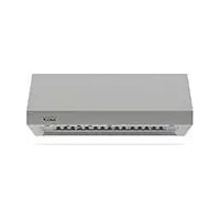
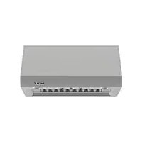
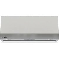
| Product Type | Kitchen Hood |
| Brand | Wolf |
| Model | VC48S |
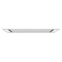
| Width | 46 1/4 in (1 175 mm) |
| Depth | 20 in (508 mm) |
| Installation Height (from countertop) | 36 to 84 in (914 to 2 134 mm) |
| Electrical Supply | 120 V AC, 60 Hz, dedicated 15 A circuit |
| Maximum Airflow | 600 ft³/min (CFM) |
| Duct Diameter | 6 in (152 mm) round, rigid metal |
| Ventilation Type | Internal or Inline/Remote |
| Filters | Removable Grease Filters (regular cleaning required) |
| Recirculation Operation | Possible with optional kit (recirculation kit) |
| Control Panel | Right side (front view) |
| Housing Material | Stainless Steel (estimated) |
| Lighting | Not specified (likely integrated LED) |
| Sound Level | Varies depending on duct configuration and fan |
| Ceiling Installation | Yes, requires support frame (min. load 100 lb / 45 kg) |
| Appliance Weight | Approximately 50 lb (23 kg) (estimated) |
| Backdraft Damper | Integrated (backdraft shutter) |
| Warranty | Consult the manual or Wolf website |
Frequently Asked Questions - VC48S WOLF
User questions about VC48S WOLF
0 question about this device. Answer the ones you know or ask your own.
Ask a new question about this device
Download the instructions for your Basket in PDF format for free! Find your manual VC48S - WOLF and take your electronic device back in hand. On this page are published all the documents necessary for the use of your device. VC48S by WOLF.
USER MANUAL VC48S WOLF
Ceiling-Mounted Hood
Installation Guide
SPECIFICATIONS, INSTALLATION, AND MORE

Contents
3 Ceiling-Mounted Hood
4 Site Preparation
6 Specifications
8 Hood Installation: Internal Blower
11 Hood Installation: In-Line/Remote Blower
14 Troubleshooting
Features and specifications are subject to change at any time without notice. Visit wolfappliance.com/specs for the most up-to-date information.
Important Note
To ensure this product is installed and operated as safely and efficiently as possible, take note of the following types of highlighted information throughout this guide:
IMPORTANT NOTE highlights information that is especially important.
CAUTION
Indicates a situation where minor injury or product damage may occur if instructions are not followed.
WARNING
States a hazard that may cause serious injury or death if precautions are not followed.
IMPORTANT NOTE: Throughout this guide, dimensions in parentheses are millimeters unless otherwise specified.
IMPORTANT NOTE: Save these instructions for the local electrical inspector.
Product Information
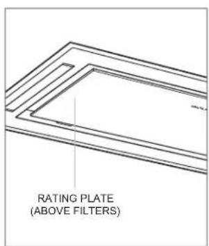
Important product information, including the model and serial number, are listed on the product rating plate. The rating plate is located under the left side of the hood, above the filters (filters must be removed). Refer to the illustration below.
If service is necessary, contact Wolf Factory Certified Service with the model and serial number. For the name of the nearest Wolf Factory Certified Service or for questions regarding the installation, visit the Product Support section of our website, wolfappliance.com, or call Wolf Customer Care at 800-222-7820.
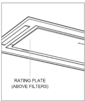
Rating plate location
IMPORTANT INSTRUCTIONS
WARNING
TO REDUCE THE RISK OF FIRE, ELECTRIC SHOCK, OR INJURY TO PERSONS, OBSERVE THE FOLLOWING:
a) Installation work and electrical wiring must be done by qualified person(s) in accordance with all applicable codes and standards, including fire-rated construction.
b) Sufficient air is needed for proper combustion and exhausting of gases through the flue (chimney) of fuel burning equipment to prevent back drafting. Follow the heating equipment manufacturer's guideline and safety standards such as those published by the National Fire Protection Association (NFPA), and the American Society for Heating, Refrigeration and Air Conditioning Engineers (ASHRAE), and the local code authorities.
c) When cutting or drilling into the wall or ceiling, do not damage electrical wiring and other hidden utilities.
d) Ducted fans must always be vented to the outdoors.
Ducting
WARNING
Use only metal ducting.
IMPORTANT NOTE: Consult a qualified HVAC professional for specific installation and ducting applications.
The hood accommodates a 6" (152) round duct. Use only rigid metal ducting.
A straight, short duct run is most effective and will ensure proper performance. If the duct run exceeds 50' (15 m), a higher CFM blower may be required to maintain proper airflow. A remote blower installed on a short duct run may increase the potential for noise.
Internal and in-line blowers require a roof or wall cap. Use sheet metal screws and aluminum tape or high temperature duct tape to seal joints between ducting sections.
The hood includes a backdraft damper. Local codes may require the use of an additional backdraft and/or make-up air damper. Contact your local HVAC professional for specific requirements.
A make-up air damper is available through an authorized Wolf dealer. For local dealer information, visit the find a showroom section of our website, wolfappliance.com.
CAUTION
To reduce the risk of fire and to properly exhaust air, duct air outside. Do not vent exhaust air into spaces within walls, ceilings, attics, crawl spaces, or garages.
CAUTION
To reduce the risk of fire and electrical shock, only install this range hood with remote blower models rated a maximum of 3A suitable for use with solid state speed control or internal blowers manufactured by Wolf, "Blower—600 CFM".
Ducting
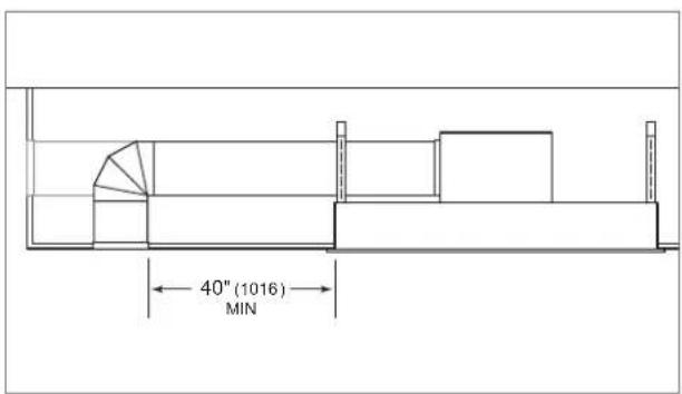
RECIRCULATING APPLICATION
The hood with an internal blower, can be installed in a recirculating application. The air discharge must be a minimum of 40" (1016) from every side of the hood. Refer to the illustration below.
Ductwork and vent cover are not provided.
A recirculation kit, available through an authorized Wolf dealer, is required.
Recirculating application
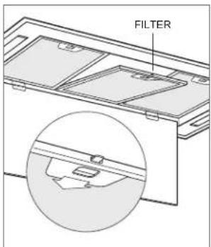
Filter Removal
To access the grease filters, pull down the front edge of the bottom panel of the hood and allow it to rotate downward.
To remove the filters, refer to the illustration below.
IMPORTANT NOTE: Do not operate the ventilation hood without the grease filters.
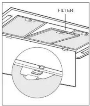
Filter removal
Installation Requirements
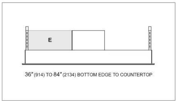
Install the hood 36" (914) to 84" (2134) from the bottom of the hood to the countertop.
The hood requires a 600 CFM internal or in-line blower assembly, or a 600 CFM remote blower assembly, available through an authorized Wolf dealer.
Consult a qualified HVAC professional for specific installation and ducting applications.
Electrical Requirements
Installation must comply with all applicable electrical codes.
Locate the electrical supply within the shaded area shown in the illustration below. Allow a minimum 12" (305) wire (Romex®) for connection. A separate circuit servicing only this appliance is required.
ELECTRICAL REQUIREMENTS
Electrical Supply grounded, 120 VAC, 60 Hz
Service 15 amp dedicated circuit
Electrical location
Rating plate location
Ceiling Preparation
Refer to the chart and illustrations below for opening dimensions and typical framing. Construct the framing using minimum 2" x 4" lumber. Framing must be able to support a minimum of 100 lb (45 kg).
HOOD W
36" Hood 34 ^1/2 " (873)
48" Hood 46 ^1/4 " (1175)
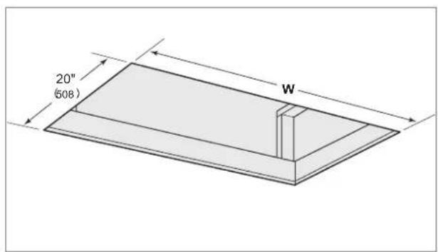
Opening dimensions
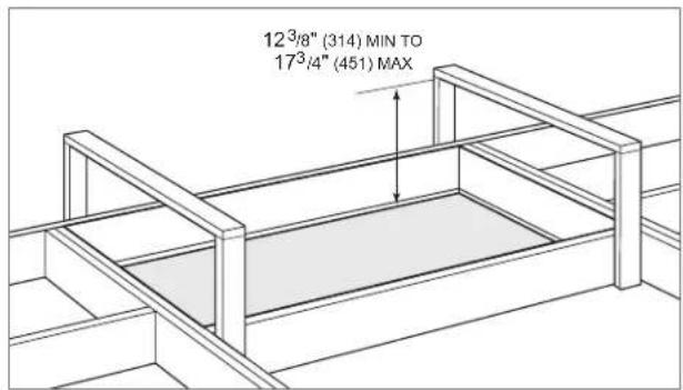
Support framing (typical)
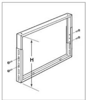
Mounting Brackets
To determine the height of the adjustable mounting brackets, subtract 5" (127) from the support framing height (e.g. support framing height - 5" = H).
Use the 38 " (10) length screws provided to secure the brackets. Refer to the illustration below.
natural_image
Technical line drawing of a rectangular electronic device with labeled dimensions H and support points (no text or symbols beyond annotations)Bracket adjustment
Hood Installation—Internal Blower
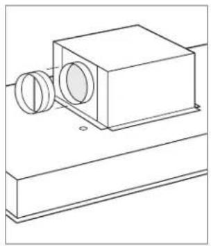
BLOWER BOX REMOVAL
Remove the blower box from the hood by removing the four screws. Refer to the illustration below.
natural_image
Technical line drawing of a mechanical component with mounting base and circular opening (no text or symbols)Blower box removal
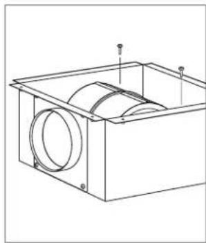
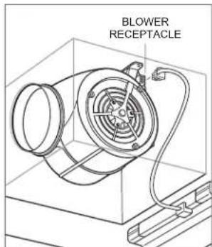
BLOWER INSTALLATION
IMPORTANT NOTE: The blower must be installed and plugged in prior to making the electrical connection to the hood.
1 Insert the round discharge on the blower into the round discharge on the blower box.
2 Secure the blower to the blower box with the two screws provided with the blower. Refer to the illustration below.
3 Rotate the blower box so the 6" (152) round discharge is properly located. Refer to the illustration below.
4 Secure the blower box to the hood with the existing screws.
natural_image
Technical line drawing of a mechanical housing or enclosure with internal components and mounting holes (no text or symbols)Internal blower installation
natural_image
Technical line drawing of a mechanical housing or enclosure with circular components and mounting base (no text or symbols)Discharge direction
Hood Installation—Internal Blower
DAMPER INSTALLATION
Place the round damper on the round discharge and secure with duct sealing tape. Refer to the illustration below.
natural_image
Technical line drawing of a mechanical device with two circular components mounted on a base (no text or symbols)Damper installation
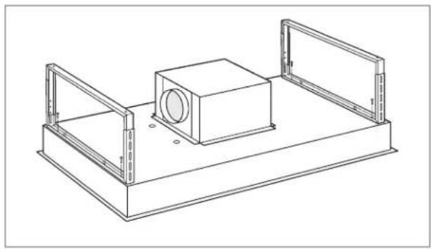
BRACKET INSTALLATION
Secure the two mounting brackets to the hood using the four 916 " (14) length screws provided. Refer to the illustration below.
natural_image
Technical line drawing of a mechanical housing or enclosure with two transparent plates and a central cylindrical component (no text or symbols)Bracket installation
Hood Installation—Internal Blower
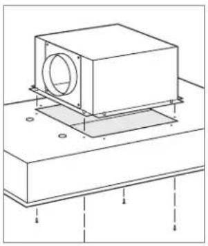
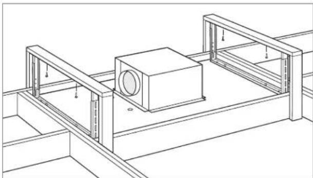
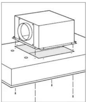
HOOD INSTALLATION
IMPORTANT NOTE: Mounting hardware is not provided.
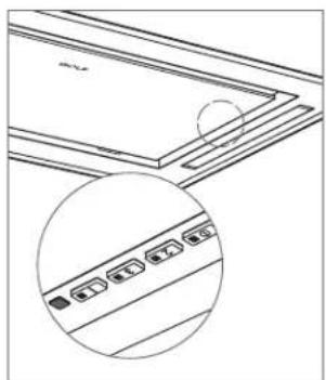
1 Verify the control panel on the hood is located on the right. Refer to the illustration below.
2 Insert the hood into the opening.
3 Secure the hood to the ceiling support framing. Refer to the illustration below.
4 Connect the ductwork to the damper, then secure with duct sealing tape.

natural_image
Technical line drawing of a layered panel structure with a magnified inset showing internal components (no text or symbols)Control panel location
natural_image
Technical line drawing of a mechanical assembly with mounting brackets and a central housing (no text or symbols)Hood installation
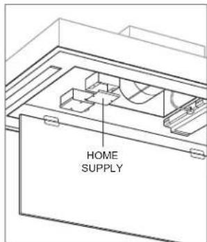
WIRING CONNECTIONS
WARNING
Before making electrical connections, make sure the electrical power is turned off at the service panel.
1 Remove the knockout above the home supply junction box, then insert the home electrical supply (Romex®) into the electrical box. Refer to the illustration below.
2 Secure the electrical supply to the electrical box with a UL or C/UL approved connector (not provided).
3 Connect the green or bare ground wire to the green grounding screw. Use appropriate wire connectors (not provided) to connect white to white and black to black.
4 Place all wiring connections inside the electrical box and install the cover. Verify all wires are secure and not pinched between the cover and electrical box.
5 Insert the plug from the control board housing into the receptacle on the blower. Refer to the illustration below.
Wiring connections
Blower connection
Hood Installation—In-Line/Remote Blower
BLOWER BOX REMOVAL
1 Remove the blower box from the hood by removing the four screws. Refer to the illustration below.
2 Discard the blower box and screws.
natural_image
Technical line drawing of a mechanical assembly with a central component and mounting base (no text or symbols)Blower box removal
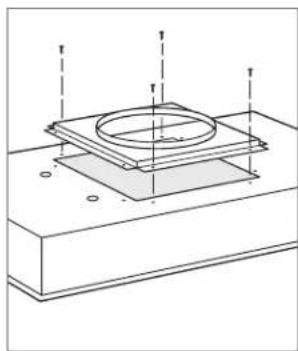
FLANGE INSTALLATION
1 Place the flange on the top of the hood.
2 Secure the flange to the hood with the 14 " (6) length screws provided. Refer to the illustration below.
natural_image
Technical diagram of a mechanical assembly with concentric rings and mounting base (no text or symbols)Flange installation
Hood Installation—In-Line/Remote Blower
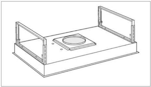
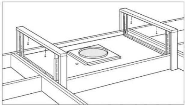
BRACKET INSTALLATION
Secure the two mounting brackets to the hood using the four 916 " (14) length screws provided. Refer to the illustration below.
natural_image
Technical line drawing of a rectangular enclosure with two side brackets and a central circular component (no text or symbols)Bracket installation
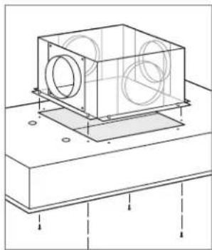
HOOD INSTALLATION
IMPORTANT NOTE: Mounting hardware is not provided.
1 Verify the control panel on the hood is located on the right. Refer to the illustration below.
2 Insert the hood into the opening.
3 Secure the hood to the ceiling support framing. Refer to the illustration below.
4 Connect the ductwork to the damper, then secure with duct sealing tape.
natural_image
Technical line drawing of a layered structure with an inset magnified view showing four labeled components (no text or symbols present)Control panel location
natural_image
Technical line drawing of a structural frame with supports and a central circular component (no text or symbols)Hood installation
Hood Installation—In-Line/Remote Blower
WIRING CONNECTIONS
WARNING
Before making electrical connections, make sure the electrical power is turned off at the service panel.
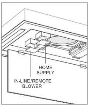
Home Supply:
1 Remove the knockout above the home supply junction box, then insert the home electrical supply (Romex®) into the electrical box. Refer to the illustration below.
2 Secure the electrical supply to the electrical box with a UL or C/UL approved connector (not provided).
3 Connect the green or bare ground wire to the green grounding screw. Use appropriate wire connectors (not provided) to connect white to white and black to black.
4 Place all wiring connections inside the electrical box and install the cover. Verify all wires are secure and not pinched between the cover and electrical box.
Wiring connections
In-Line/Remote Supply:
1 Remove the knockout above the in-line/remote blower junction box, then insert the blower electrical supply (Romex®) into the electrical box.
2 Secure the electrical supply to the electrical box with a UL or C/UL approved connector (not provided).
3 Connect the green or bare ground wire to the green grounding screw. Use appropriate wire connectors (not provided) to connect white to white and black to black.
4 Place all wiring connections inside the electrical box and install the cover. Verify all wires are secure and not pinched between the cover and electrical box.
5 Insert the plug from the control board housing into the receptacle on the side of the junction box.
Completion
1 Install the grease filters. Refer to the illustration below.
2 Rotate the bottom cover upward and into position.
3 Turn on the electrical supply at the circuit panel and verify operation.
Filter installation
Troubleshooting
IMPORTANT NOTE: If the ventilation hood does not operate properly, follow these troubleshooting steps:
- Verify electrical power is supplied to the ventilation hood.
- Verify proper wiring connections.
- If the ventilation hood does not operate properly, contact Wolf Factory Certified Service. Do not attempt to repair the hood. Wolf is not responsible for service required to correct a faulty installation.
Contenido
natural_image
Technical line drawing of a mechanical assembly with a central housing and mounting base (no text or symbols)natural_image
Technical line drawing of a rectangular mechanical housing with internal components and mounting holes (no text or symbols)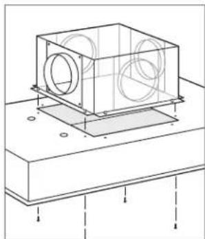
natural_image
Technical line drawing of a mechanical housing or enclosure with circular components and mounting base (no text or symbols)natural_image
Technical line drawing of a mechanical device with cylindrical components mounted on a base (no text or symbols)natural_image
Technical line drawing of a mechanical housing or enclosure with two rectangular components and mounting brackets (no text or symbols)natural_image
Technical line drawing of a mechanical component with a circular inset showing four labeled slots (no text or symbols present)natural_image
Technical line drawing of a mechanical assembly with mounting brackets and a central cylindrical component (no text or symbols)natural_image
Technical line drawing of a mechanical component with mounting base and circular opening (no text or symbols)natural_image
Technical line drawing of a mechanical assembly with concentric rings and mounting base (no text or symbols)natural_image
Technical line drawing of a rectangular enclosure with two side brackets and a central circular opening (no text or symbols)natural_image
Technical line drawing of a layered panel structure with an inset showing a close-up of a component (no text or symbols)natural_image
Technical line drawing of a structural frame with supports and a central circular component (no text or symbols)natural_image
Technical line drawing of a rectangular electronic device with labeled dimensions H and mounting holes (no text or symbols beyond basic geometry)natural_image
Technical line drawing of a mechanical assembly with a central housing and mounting base (no text or symbols)natural_image
Technical line drawing of a mechanical housing or enclosure with internal components and mounting holes (no text or symbols)natural_image
Technical line drawing of a mechanical housing with circular components and mounting base (no text or symbols)natural_image
Technical line drawing of a mechanical housing with two circular components mounted on a base (no text or symbols)natural_image
Technical line drawing of a mechanical housing or enclosure with two transparent plates and a central cylindrical component (no text or symbols)Installation des supports
natural_image
Technical line drawing of a layered panel structure with an inset magnified view showing internal components (no text or symbols)natural_image
Technical line drawing of a mechanical assembly with mounting brackets and a central cylindrical component (no text or symbols)Installation de la hotte
CONNEXIONS
AVERTISSEMENT
natural_image
Technical line drawing of a mechanical assembly with a central component and mounting base (no text or symbols)natural_image
Technical diagram of a mechanical assembly with concentric rings and mounting base (no text or symbols)Installation de la bride
natural_image
Technical line drawing of a rectangular enclosure with two side brackets and a central circular opening (no text or symbols)Installation des supports
INSTALLATION DE LA HOTTE
natural_image
Technical line drawing of a roof structure with a circular detail view showing internal components (no text or symbols)natural_image
Technical line drawing of a structural frame with supports and a central circular component (no text or symbols)Installation de la hotte
WOLF APPLIANCE, INC. P.O. BOX 44848 MADISON, WI 53744 WOLFAPPLIANCE.COM 800.222.7820
828138 REV-E 3/2023