DKC054A1BSL2DB - Beer dispenser DANBY - Free user manual and instructions
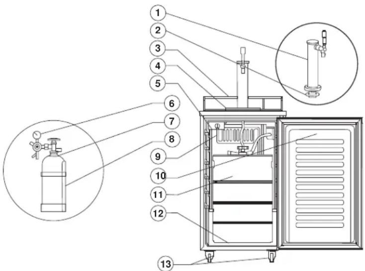
Find the device manual for free DKC054A1BSL2DB DANBY in PDF.

| Brand | Danby |
| Model | DKC054A1BSL2DB |
| Product Type | Beer dispenser (kegerator) |
| Accepted keg sizes | 1/2 barrel (59 L), 1/4 barrel (30 L), 1/6 barrel (20 L), 1/8 barrel (15 L) |
| Dimensions (approx.) | 61 x 61 x 84 cm (W x D x H) |
| Weight (approx.) | 45 kg |
| Power supply | 115 V, 60 Hz, grounded |
| Gas type | CO2 (empty cylinder included) |
| Pressure regulator | Yes, built-in, range 8-12 psi |
| Adjustable thermostat | Yes, with max/min position and off (0) |
| Automatic defrost | Yes, drains into evaporation tray |
| Refrigerator conversion | Possible (removal of dispensing components) |
| Reversible door | Yes, left or right opening |
| Casters | 4 casters, 2 with front brakes |
| Included accessories | Beer tower, regulator, CO2 cylinder, hoses, coupler, keg dip tube, handle, wrench, caps, metal plate, shelves |
| Beer line maintenance | Every 3 weeks or every 2 kegs |
| Faucet cleaning | Weekly or before each use |
| Warranty | 1 year limited (functional parts) |
| Customer service | 1-800-263-2629 (Danby) |
| Keg compatibility | Standard US keg with Sankey coupler (max diameter 41 cm, max height 59.4 cm) |
Frequently Asked Questions - DKC054A1BSL2DB DANBY
User questions about DKC054A1BSL2DB DANBY
0 question about this device. Answer the ones you know or ask your own.
Ask a new question about this device
Download the instructions for your Beer dispenser in PDF format for free! Find your manual DKC054A1BSL2DB - DANBY and take your electronic device back in hand. On this page are published all the documents necessary for the use of your device. DKC054A1BSL2DB by DANBY.
USER MANUAL DKC054A1BSL2DB DANBY
natural_image
Grid of eight squares in varying shades of gray, arranged in two rows and three columns (no text or symbols)Danby
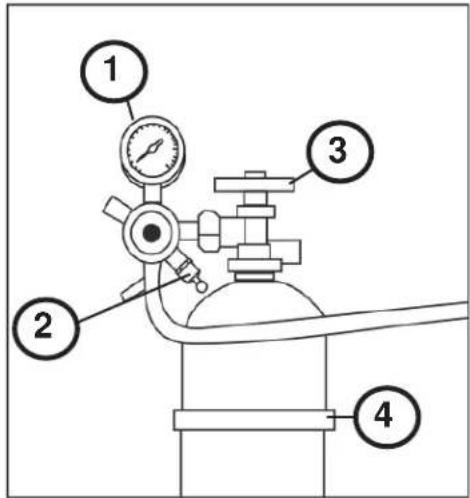
- Pressure gauge dial
- Pressure relief ring
- Open / Close valve
- Tank strap
Ensure the CO_2 tank is empty before courier or 3^rd party transport.
DANGER - A full or partially full CO₂ tank is under extreme pressure. Uncontrolled release of pressure is extremely dangerous. The instructions below use the regulator to control the release of this pressure in a safe manner. Do not bypass the regulator.
- Ensure tank is secure
- Fully open valve by turning counterclockwise. Pressure gauge dial will show a value if tank contains pressure.
- Gently pull pressure relief ring. Released gas should be heard.
- The pressure dial will read zero when the tank is empty. Continue to hold pressure relief open until tank is empty.
- Release the pressure relief ring.
-
Fully close valve by turning clock-wise.
-
Cadran de manomètre
- Anneau de limitation de pression
- Soupape de l'ouverture / fermeture
- Sangle du réservoir
Owner's Use and Care Guide 1-16
- Welcome
- Important Safety Information
- Features
• Installation Instructions
• Operation Instructions - Care and Maintenance
- Troubleshooting
- Warranty
GLACIÈRE DE BIÈRE PRESSION
Includes American Sankey tap coupler only.
Welcome to the Danby family. We are proud of our quality products, and we believe in dependable service. We suggest that you read this Owner's Manual before plugging in your new appliance as it contains important operational information, safety information, troubleshooting and maintenance tips to ensure the reliability and longevity of your appliance. Visit www.Danby.com to access self-service tools, FAQs and much more. For additional assistance call 1-800-263-2629.
Note the information below; you will need this information to obtain service under warranty. To receive service, you must provide the original receipt.
Model Number:
Serial Number:
Date of Purchase:
NEED HELP?
Before you call for service, here are a few things you can do to help us serve you better:
Read this Owner's Use and Care Guide:
It contains instructions to help you use and maintain your appliance properly.
If you received a damaged appliance:
Immediately contact the retailer (or builder) that sold you the appliance.
Save time and money:
Check the Troubleshooting section at the end of the guide before calling. This section helps you solve common problems that may occur.
If you do need service, you can relax, knowing help is only a phone call away.

natural_image
Simple black-and-white icon of a telephone handset inside a circle (no text or symbols)1-800-26- Danby
(1-800-263-2629)

IMPORTANT WARNING
DANGER: Risk of child entrapment. Before you throw away your old appliance:
• Take off doors or remove the gasket.
- Leave the shelves in place so that children may not easily climb in.
DON'T WAIT! DO IT NOW!
To avoid installation or operation difficulties, read these instructions thoroughly.
- This appliance must be grounded. Connect only to a properly grounded outlet. See Grounding Instructions section.
- Do not operate this appliance if it has a damaged power cord or plug, if it is not working properly, or if the appliance has been damaged or dropped. If the power cord is damaged it must be replaced by the manufacturer, its service agent or similarly qualified person to avoid hazard.
- Never allow children to operate, play with, or crawl inside the appliance.
- Never clean appliance parts with flammable fluids. The fumes can create a fire hazard or explosion.
- Do not store or use gasoline or any other flammable vapors or liquids in the vicinity of this or any other appliance. The fumes can create a fire hazard or explosion.
- Do not splice the power cord that is equipped with this appliance.
- Keep power cord away from heated surfaces.
- Do not immerse power cord, plug or the appliance itself in water.
- Do not use this product near water for example, in a wet basement, laundry room or near a sink.
- Do not use corrosive chemicals or vapors in this appliance.
- Use this appliance only for its intended use, as described in this manual.
- Do not store open containers in this appliance.
- Do not cover or block any openings on the appliance.
- Do not store perishable food items such as (but not limited to) meats and dairy products in your wine cooler. This appliance does not get cold enough to be food safe.
- This appliance is intended for household use only. Do not operate or store this appliance outdoors.
- This appliance should be serviced only by qualified service personnel. Contact the nearest authorized service facility for examination, repair or adjustment.
- Before connecting the appliance to a power source, let it stand upright for approximately 6 hours; this will reduce the possibility of a malfunction in the cooling system from handling during transportation.
SAVE THESE INSTRUCTIONS!

Important Safety Information READ AND FOLLOW ALL SAFETY INSTRUCTIONS
GROUNDING INSTRUCTIONS
This appliance must be grounded. In the event of an electrical short circuit, grounding reduces the risk of electric shock by providing an escape wire for the electric current. This appliance is equipped with a cord having a grounding wire with a grounding plug. The plug must be plugged into an outlet that is properly installed and grounded
WARNING - Improper use of the grounding plug can result in a risk of electric shock. Consult a qualified electrician or service agent if the grounding instructions are not completely understood, or if doubt exists as to whether the appliance is properly grounded.
If the outlet is a standard 2-prong wall outlet, it is your personal responsibility and obligation to have it replaced with a properly grounded 3-prong wall outlet.
For best operation, plug this appliance into its own electrical outlet to prevent flickering of lights, blowing of fuse or tripping of circuit breaker
DO NOT USE AN EXTENSION CORD
Use an exclusive 115V wall outlet. Do not connect your appliance to extension cords or together with another appliance in the same wall outlet. Do not splice the cord. Do not under any circumstances cut or remove the third ground prong from the power cord. Do not use an adapter plug with this appliance.
SAFETY REQUIREMENTS
Ensure that component parts shall be replaced with like components and that servicing shall be done by factory authorized service personnel, so as to minimize the risk of possible ignition due to incorrect parts or improper service.
This appliance must be grounded. In the event of an electrical short circuit, grounding reduces the risk of electrical shock by providing an escape wire for the electrical current. The serial rating plate indicates the voltage and frequency the appliance is designed for.
WARNING! EXPLOSION HAZARD! Risk of fire or explosion due to puncturing of refrigerant tubing. Do not use sharp objects to aid in defrost. Please handle with care. Keep flammable materials and vapors such as gasoline away from the refrigerator. Use nonflammable cleaner.
Disposal of this unit should be in accordance with federal and local regulations.
This appliance is not intended for use by persons (including children) whose physical, sensory or mental capabilities may be different or reduced, or who lack experience or knowledge, unless such persons receive supervision or training to operate the appliance by a person responsible for their safety.
WARNING: Keep ventilation openings, in the appliance enclosure or in the built-in structure, clear of obstruction.
WARNING: Do not use mechanical devices or other means to accelerate the defrosting process, other than those recommended by the manufacturer.
WARNING: Do not damage the refrigerant circuit.
WARNING: Do not use electrical appliances inside the food storage compartments of the appliance, unless they are of the type recommended by the manufacturer.
SAVE THESE INSTRUCTIONS!

Important Safety Information READ AND FOLLOW ALL SAFETY INSTRUCTIONS
WARNING: CO₂ CAN BE DANGEROUS!
CO 2 Cylinders, when charged, contain high pressure compressed gas which can be hazardous if not handled properly. Read and understand the following procedures for CO 2 cylinders before installation:
- Always check the D.O.T. (Department of Transportation) as well as the T.C. (Transport Canada) test date located on the neck of the cylinder before installation. If the date is older than five (5) years, do not use! Return the gas cylinder to a gas supplier for re-certification (service charges may be applicable).
- Always connect a CO_2 gas cylinder to a regulator. Failure to do so could result in an explosion which can possibly result in death or injury when the cylinder valve is opened.
- Always follow correct procedures when cylinders are changed as per local codes.
- Always secure a CO_2 gas cylinder in an “upright” position.
- Always keep a CO _2 gas cylinder away from heat. Store extra cylinders in a cool place (preferably 70°F/21°C). Securely fasten with a chain in an upright position when storing.
- Always ventilate and leave the area immediately after any leakage of CO_2 .
- Never connect a CO_2 gas cylinder directly to a beer keg.
- Never drop or throw a CO_2 cylinder.
- Never connect a keg without at least one safety pressure release. There are two safety mechanisms in the pressure system;
- One at or on the CO, regulator.
- One at or on the product container coupler in the pressure gas line.
Note: The regulator and keg coupler supplied with this unit are inclusive of such safety mechanisms.

CO _2 WARNING
If it becomes difficult to breathe and/or your head starts to ache, abnormal concentrations of carbon dioxide (CO _2 ) may be present in the area.
CLOSE THE MAIN VALVE ON THE CO _2 CYLINDER, VENTILATE AND LEAVE THE ROOM IMMEDIATELY!

IMPORTANT WARNING
Beer is easily available with Danby's Keg Cooler, however, it is not intended to be available to people under the legal age to consume beer. Danby does not assume liability for the unlawful use or consumption of the beer.
PLEASE DRINK RESPONSIBLY AND PLEASE DON'T DRINK AND DRIVE!
SAVE THESE INSTRUCTIONS!
INCLUDED ACCESSORIES
Remove and inspect all accessories supplied with this unit and ensure they are all present and in good condition. In the event any of the accessories are missing and/or not in good condition, please call Danby toll free at 1-800-263-2629 and speak with one of our Consumer Service Representatives.
- Beer Tower
- Rubber Gasket (may not be required in all unit configurations)
- Safety Guard Rail
- Drip Tray
- Adjustable Thermostat
- CO _2 Regulator
- CO _2 Gas Cylinder
- CO _2 Gas Cylinder Support
- Evaporator
- Door
- Beer Keg (not included)
- Metal Plate
- Castors (4)
BEFORE USING YOUR KEG COOLER
- Remove the exterior and interior packaging.
- Check to be sure you have all the following parts:
• 2 Safety Guard Rail - 1 drip tray (2 pieces)
• 1 CO 2 Cylinder support
• 1 CO 2 Regulator
• 1 CO 2 Empty Cylinder
• 1 CO 2 Gas line hose (coloured)
• 1 Beer Hose
• 1 Beer keg couplers - 1 Beer tower
• 1 Pull handle (Beer tower faucet)
• 4 Plugs: For guard rail holes
• 1 metal plate for cabinet bottom - 3 Wire shelf
• 1 steel clamp for coloured hose -
2 plastic washers for front casters
• 4 Casters (2 front with locks) -
Before plugging in the keg cooler, let it stand upright for approximately 6 hours. This will reduce the possibility of a malfunction in the cooling system from handling during transportation.
- Clean the interior surface with lukewarm water using a soft cloth.
INSTALLATION OF KEG COOLER
- This appliance is designed to be free standing only and should not be recessed or built-in.
- Place your keg cooler on a floor that is strong enough to support the unit when it is fully loaded.
- Allow 8-12 cm (3-5 inches) of space between the back and sides of the keg cooler and any adjacent wall to allow proper air circulation to cool the compressor.
- Locate the keg cooler away from direct sunlight and sources of heat (stove, heater, radiator, etc.). Direct sunlight may affect the acrylic coating and heat sources may increase electrical consumption. Extreme cold ambient temperatures may also cause the keg cooler not to perform properly.
- This unit is not designed for outside installation (i.e. garages, porches, patios etc.).
- Avoid locating the keg cooler in excessive humidity.
- Plug the keg cooler into a dedicated, properly installed-grounded wall outlet. Do not under any circumstance cut or remove the third ground prong from the power cord. Any questions concerning power and or grounding should be directed toward a certified electrician or an authorized service centre.
- After plugging the appliance into a wall outlet, allow the unit to cool down for 2-3 hours before placing any contents in the keg cooler compartment.

WARNING
CO _2 GAS CAN BE DANGEROUS
CO 2 cylinders contain high-pressure compressed gas which can be hazardous if not handled properly. Make sure you read and understand all safety procedures for CO 2 cylinders before installation.
BEER KEG INSTALLATION INSTRUCTIONS
Keg Installation Sketch
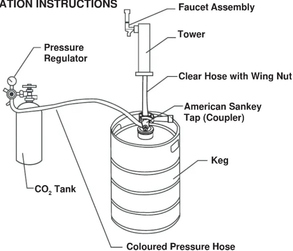
BEER KEG INSTALLATION INSTRUCTIONS
Install the four castors. The two locking castors should be placed at the front. Four screw holes have been pre-drilled into the unit's bottom at each corner for each castor. Put the plastic washers provided on the front castors before installing them.
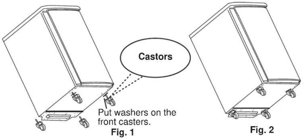
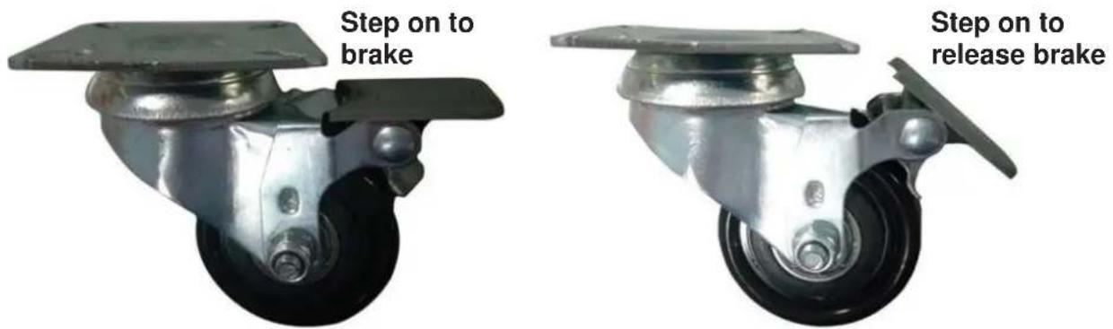
Castor Brake Guide
The two front castors are supplied with brakes to ensure the unit does not move excessively while being used. It is recommended to engage the brakes while the unit is in use to avoid damage to the unit, the contents or your personal property.
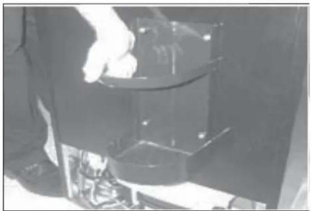
Installation of CO_2 Cylinder Support
Install the metal support provided onto the four studs located on the exterior back wall of the chassis.
Align the holes in the support with the studs and push down firmly.
natural_image
Person handling a transparent container with mechanical components (no visible text or symbols)
Installation Instructions
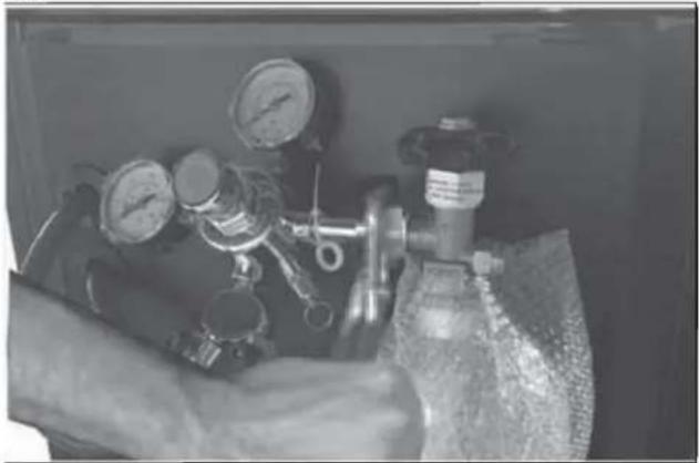
Installation of CO_2 Cylinder and CO_2 Regulator
The CO2 cylinder does not come fi lled. The cylinder must be ^2fi lled with CO2 before use.
Place the charged cylinder into the support stand.
Attach the CO2 regulator to the cylinder by turning the regulator nut onto the cylinder valve, making sure the washer is securely inserted into the connecting nut. Tighten snug using an adjustable wrench (not supplied) and ensure there are no leaks, i.e. no hissing sounds when the CO2 is turned on.
natural_image
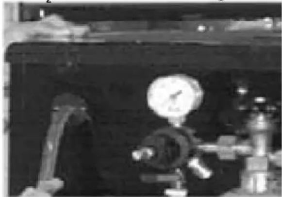
Industrial piping system with gauges and valves, no visible text or symbolsInstallation of CO₂ Air Line Outside Cabinet and CO₂ Air Line Hose to Regulator
Remove the plug located at the exterior back of the cabinet, in the top left hand corner. Save the plug for later use if you decide to convert the unit to a refrigerator.
Feed the gas line through the cabinet and out through the uncovered hole.
Attach the open end of the hose to the hose barb connection on the regulator. Secure the hose by using one clamp provided. Use pliers or a screwdriver to tighten the clamp to prevent leaks.
natural_image
Industrial equipment setup with pressure gauge and tubing (no visible text or symbols)Installation of the Beer Tower
- Remove the plug from the top of the fridge cabinet by twisting and pulling out. Save the plug for later use if you decide to convert the unit to a refrigerator.
- Unravel the beer line (clear hose) from the tower and insert the beer line and wing nut through the uncovered hole on top of the unit.
- Lock the beer tower assembly to the top of the unit and make sure to position the beer faucet so it is aligned with the front of the cabinet.
- The rubber gasket can be used to make the connection between the tower and the cooler tighter if needed. If the beer tower will not turn to lock in place, try removing the rubber gasket. (The rubber gasket may not be required in all unit confi gurations).
- If the tower faucet is leaking or if the beer is very foamy, ensure that the washers inside the faucet are intact. Replace the washers with spare parts from the accessory bag, if necessary.
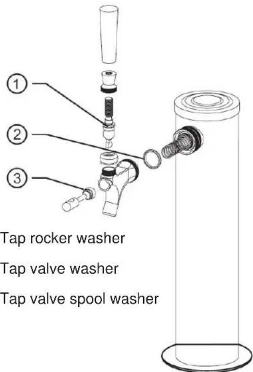
- Tap rocker washer
- Tap valve washer
- Tap valve spool washer

Installation Instructions
Installation of the Protective Metal Plate
The protective metal plate should be installed on the bottom of the inside of the cabinet. This plate should always be installed when a keg is in place to protect the floor of the cabinet against damage.
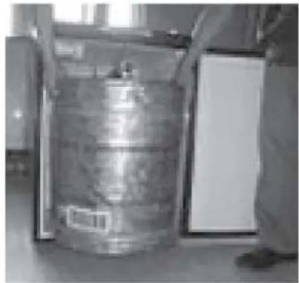
Installation of the Beer Keg
- Position the beer keg directly in front of the open door. Using keg handles only, carefully lift the beer keg.
- To place the beer keg inside the cabinet, brace your knees behind the beer keg. Lift the front of the keg just enough so the front end of the keg is resting on the front edge of the keg cooler bottom cabinet.
- Grasp the keg handles and slide it all the way into the cabinet.
Note: Two people should lift the keg to avoid back injury.
natural_image
Exterior view of a large metallic cylindrical container with a label, placed indoors near a window (no visible text or symbols)Installation of the CO_2 Air Line Hose
Attach the end of the air line (coloured) hose provided to the hose connection on the side of the coupler. Ensure that the check valve is inserted into the connection, number 4 on the image below.
If, after assembly, beer will not flow, ensure that the check valve has a small hole in it. If there is no hole in the check valve then CO_2 cannot enter the line and the beer will not flow.
Connecting the Beer Tower to the Coupler
- Ensure all washers are properly inserted into the coupler, as per below image.
- Ensure the valve spool plastic rod is in place inside the coupler, number 2 on the below image.
- Place the wing nut attached to the end of the beer line into the top of the coupler, turning until tight.
If, after assembly, the beer is very foamy, it most likely means that a connection in the coupler is leaking and air is entering the lines. Double check all connections in the coupler and replace the washers from the accessory bag as necessary.
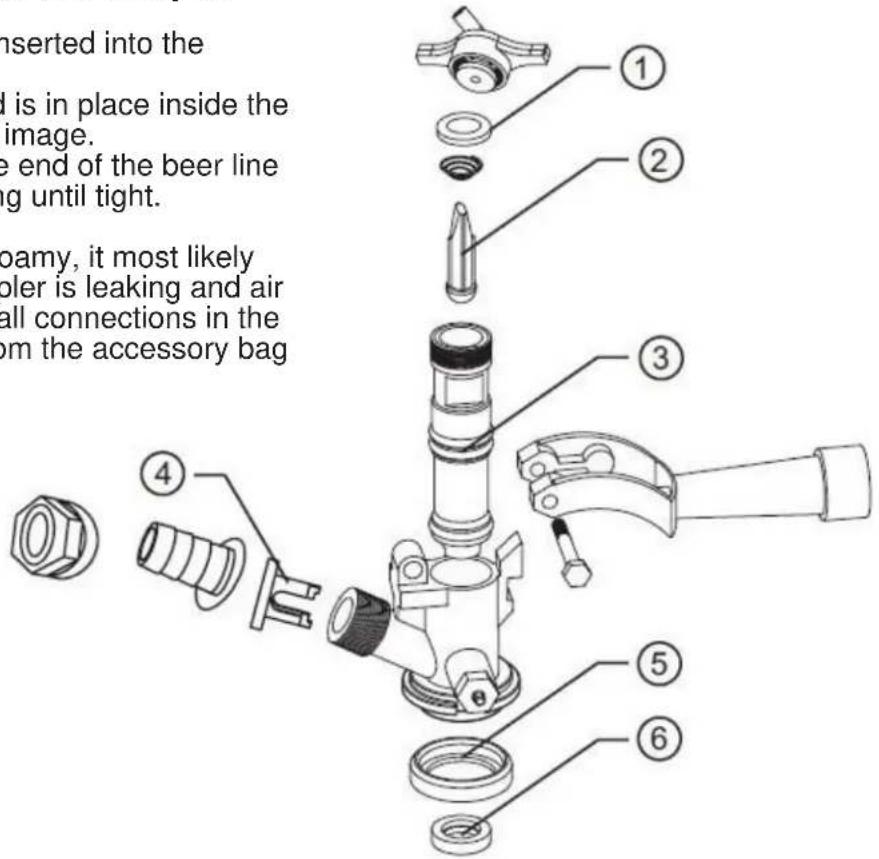
- Valve washer
- Valve spool plastic rod
- Valve spool O-type washer
- Check valve
- Valve washer
- Valve washer

Installation Instructions
Installation of the Keg Coupler
Insert the keg coupler into the locking neck of the beer keg and turn it clockwise to lock into position, making sure the keg coupler handle is in the closed position, with the handle up.
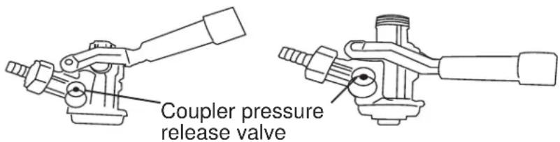
How to Tap a Keg of Beer
- Make sure the CO _2 is turned off and the valve on the regulator is in the closed position.
- Pull out and release the pressure release valve on the coupler to purge any air pressure.
- Make sure the beer tower faucet handle is in the closed position.
- Pull coupler handle out and downward until it locks into its open position. The teeth on the underside of the coupler will bite into the locking neck of the beer keg.
Note: If a keg is very tall, it may be necessary to connect the coupler to the keg before inserting the keg into the keg cooler.
Coupler closed position Coupler open position
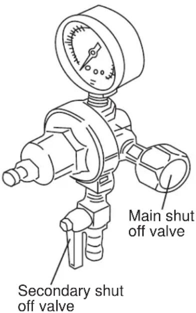
Opening the CO₂ Cylinder Main Valve
- Make sure the secondary shut-off valve (shown below in “open” position) is closed. To open the main CO₂ cylinder valve, slowly turn the main valve counter-clockwise until fully open.
- Notice the needle on the regulator gauge start to climb.
Adjusting the CO _2 Regulator
The gauge monitors low internal keg pressure and should be adjusted to read between 8-12 PSI. The pressure can be adjusted as needed. If the beer is very foamy, try turning the PSI down. If the flow of beer is very weak, try turning the PSI up.
Note: After making any adjustment to the PSI, wait 5 - 10 minutes before attempting to pour another beer to allow the pressure to equalize.
- Release adjustment lock nut marked 2.
• Using a fl at screwdriver, turn regulator screw marked 3. - To increase pressure, turn screw clockwise.
- To decrease pressure, turn screw counter-clockwise.
- Retighten lock nut marked 2.
- Open secondary shut off valve to let CO _2 flow into the keg.
- Allow several minutes for the keg to properly pressurize. Regulator gauge may drop while this happens.
Note: Listen for hissing along all connections to identify if there are any leaks.

Installation Instructions
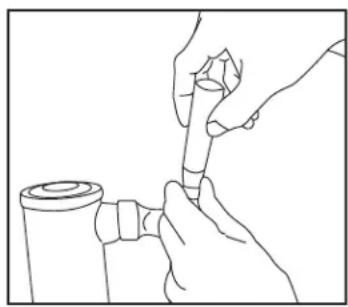
Spanner Faucet Wrench
Spanner faucet wrench (provided) is for either removing or tightening the faucet connection.
Note: To prevent leakage, use the provided wrench to further tighten the faucet connection.
natural_image
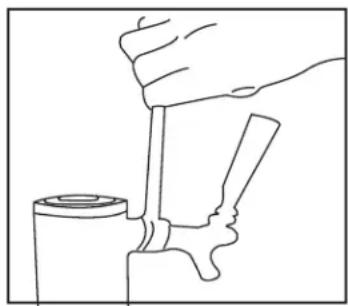
Line drawing of a hand pressing down on a mechanical component (no text or symbols)Plastic Faucet Lever
Attach the black plastic lever (pull handle) to the top of the faucet by tightening it by hand going clockwise until the end, holding in the silver nut underneath so it does not turn. If there is still a small drip from the faucet, you may have overtightend the silver nut and may need to unscrew silver snug going counter-clockwise (as shown one turn).
natural_image
Line drawing of a hand holding a cylindrical object, possibly a tool or device (no text or symbols present)DISPENSING OF BEER
- Keep beer keg refrigerated at all times.
- Never allow beer lines to dry out.
- Use clean glassware before pouring.
- Hold glass at a 45° angle, when it is 2/3 full, start to straighten glass as the glass fills.
• Always make sure the faucet handle is pushed all the way back.
| Keg sizes that can be used in your keg cooler | ||||
| 1/2 barrel 59 Liters | 15.5 gals 19 | 84 oz. 164 x 12- | oz. Glasses | |
| 1/4 barrel 30 Liters | 7.8 gals. 992 | oz. 82 x 12-oz. | Glasses | |
| 1/6 barrel 20 Liters | 5.2 gals. 661 | oz. 55 x 12-oz. | Glasses | |
| 1/8 barrel 15 Liters | 4.0 gals. 496 | oz. 41 x 12-oz. | Glasses | |
Note: The refrigerator compartment cannot accommodate the "Coors" style beveled barrel keg.
Note: Our keg cooler accepts domestic kegs up to 16-1/8" in diameter and up to 23-3/8" in height. Check with your distributor to make sure keg is correct size.
Note: It is important to allow the keg to sit upright and undisturbed, for 2 hours before tapping.

Operating Instructions
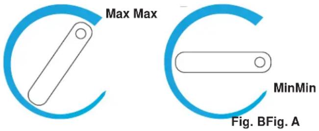
SETTING THE TEMPERATURE
The temperature is controlled by adjusting the thermostat control knob. To start the unit and achieve maximum cooling quickly:
- Turn the temperature control knob clockwise to the maximum setting on the wide, blue section of the control dial (Fig. A).
- Allow the unit to run at this setting for 3-4 hours.
- When maximum cooling is achieved, turn back the temperature control knob to a medium temperature.
- To turn off the cooling, rotate the control knob to the "0" (OFF) position (Fig. B).
AUTOMATIC DEFROSTING
There is no need to defrost the keg cooler. Defrost water collects and passes through the drain outlet in the rear wall into a tray located above the compressor, where it evaporates.
Note: If the unit is unplugged, power lost or turned off, you must wait 3 to 5 minutes before restarting the unit. If you attempt to restart before this time delay, the compressor may not start.
CONVERTING TO AN ALL REFRIGERATOR
- Turn the control knob to the "OFF" position.
- Close the main valve on the CO₂ cylinder.
- Close the secondary shut-off valve on the regulator pipe.
- Close the connection between the beer keg and the keg coupler.
- Drain any remaining beer from the lines. (We recommend cleaning at this point, please see Care and Maintenance section).
- Disconnect the beer line and CO₂ gas line from the keg coupler.
- Remove the beer keg.
- Remove the keg coupler.
- Disconnect the gas line from the CO₂ cylinder.
- Remove the CO₂ gas line from cabinet plug.
- Replace the gas line rear cabinet plug.
- Remove the beer tower. Also pull the beer line through the top of the cabinet.
- Replace the top cabinet plug.
- Adjust the temperature as desired.
Note: In order to convert the unit, you must disconnect the gas line from the regulator in order to remove it from the cabinet.
Note: If you desire a shelf in the converted "All Refrigerator" install the shelf by sliding it into the desired spot in the unit.

Operating Instructions
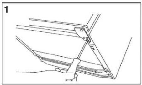
DOOR REVERSAL INSTRUCTIONS
To avoid personal injury to yourself or property, we recommend that someone assist you during the door reversal process.
This keg cooler has a door that can be set to open from the left or right side. This unit is delivered to you with the door opening from the left side. To reverse the opening direction, please follow the instructions below.
- Undo the three (3) screws in each bracket using a Phillips screwdriver.
- Remove the screws and bracket. Place to one side.
- Slide the door down about 15 cm (6") and off the top hinge pin and lift away.
- Use a flat head screwdriver to remove te pin from the top bracket. Replace it in the hinge bracket on the opposite side.
- Remove the screw from the side of the fridge where the bracket is to be re-fitted.
- Slide the fridge door back onto the top hinge, making sure it's the right way up. Screw the bottom hinge into place on the new side.
- Check that the door is aligned horizontally and vertically and that the seals are closed on all sides before finally tightening the bottom hinge.
natural_image
Technical line drawing of a mechanical clamp or bracket assembly (no text or symbols)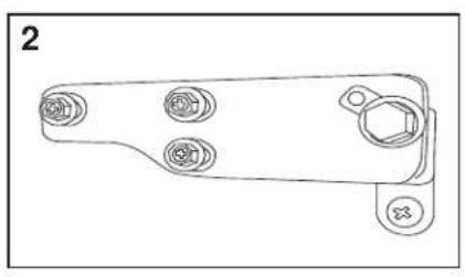
natural_image
Technical line drawing of a mechanical bracket with four circular features and a hexagonal end (no text or symbols)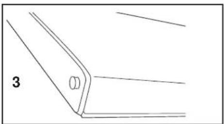
natural_image
Pure technical line drawing of a bracket or corner detail without any text, numbers, or symbols
natural_image
Line drawing of a hand holding a pen, poised to write on a document (no text or symbols present)
natural_image
Line drawing of a hand using a tool to lift a car (no text or symbols)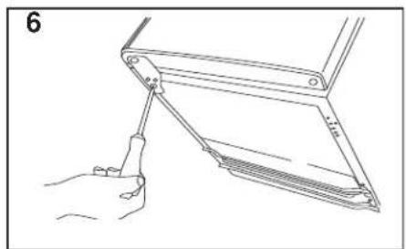
natural_image
Line drawing of a hand using a tool to lift a mechanical component (no text or symbols)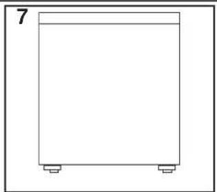
natural_image
Simple line drawing of a rectangular container with two side supports (no text or symbols)CLEANING YOUR KEG COOLER
- Turn the temperature control to "OFF", unplug the keg cooler, and remove the contents.
- Wash the inside surfaces with a warm water and baking soda solution. The solution should be 2 tablespoons of baking soda to a quart of water.
- Wash the shelves and stand with a mild detergent solution.
- Wipe down any electrical controls with a dry cloth.
- Wash the outside cabinet with warm water and mild liquid detergent. Rinse well and wipe dry with a clean soft cloth.
CLEANING YOUR BEER LINES
Beer lines have to periodically be cleaned because of a crystallized sugar build up which forms on the fittings, lines and taps commonly referred to as “beerstore”. If the “beerstore” is not completely removed in a cleaning process it will leave an unsanitary surface that can harbor microorganisms which will cause an undesirable flavour and/or cause the beer to go flat. Sufficient “beerstore” will also lead to dispense problems ranging from ‘wild’ beer (too much foam) to flat beer, regardless of the carbonation levels or quality (age) of the beer in the keg.
Scheduled line and faucet cleaning, with the proper equipment and chemical, eliminates the build-up of “beerstore” protecting the integrity of the product and condition of the dispense system and seals. The dispenser (beer) line should be cleaned approximately once every three (3) weeks or every other keg - which ever comes first. The dispenser faucet should be cleaned on a weekly basis or prior to every use if not used on a regular basis.
Note: If you have trouble manipulating the faucet lever, this is usually indicative that it may require cleaning. DO NOT apply force to move the handle in this situation, as this will likely lead to damaging the handle or faucet, and will not be covered by your warranty.
A standard cleaning kit will perform approximately eight (8) scheduled line cleanings. Line cleaning kits are readily available and can be purchased through our after sales service department.
For more information please call 1-800-26-DANBY (1-800-263-2629).
VACATION
Short Vacations - Leave the keg cooler operating during vacations of less than three (3) weeks.
Long Vacations - If the appliance will not be used for several months, remove all contents and unplug the power cord. Clean and dry the interior thoroughly. To prevent odor and mold growth, leave the door open slightly.
MOVING YOUR KEG COOLER
- Remove all the contents.
- Securely tape down all loose items inside your keg cooler.
- Tape the door shut.
- Be sure the keg cooler stays secure in the upright position during transportation. Also protect the outside of the keg cooler with a blanket or similar item.
Danby Consumer Care: 1-800-263-2629
Hours of operation:
Monday to Thursday 8:30 am - 6:00 pm Eastern Standard Time
Friday 8:30 am - 4:00 pm Eastern Standard Time
| PROBLEM POSSIBLE CAUSE | |
| The unit does not operate | Not plugged inThe circuit breaker tripped or blown fuse |
| Turns on and off frequently | The room temperature is hotter than normalThe door is open too oftenThe door is not closed completelyThe temperature control is not set correctlyThe door gasket does not seal properlyThe unit does not have proper clearance |
| Vibrations • Check that the keg cooler is level | |
| The keg cooler seems to make too much noise | The rattling noise may come from the flow of refrigerant, which is normalGurgling, caused by liquid refrigerant cycling is normalContraction and expansion of the inside walls may cause popping and crackling noisesThe keg cooler is not level |
| The door will not close properly | The keg cooler is not levelThe door was reversed and not properly reinstalledThe gasket is dirtyThe shelves or stand are out of positionThe keg is not properly centered in the unitThe casters are not attached |
| Excessive beer foam • Ensure the beer line hose from the tower and the CO2 air line hose from the CO2 regulator are attached to the correct connections on the coupler; beer line to the top of the coupler, CO2 air line to the side of the couplerCheck that there are no leaks in any connectionsEnsure that the reed valve in the CO2 connection at the coupler has a hole in itThe CO2 pressure may be set too high; try turning the pressure downEnsure that the valve spool plastic rod is inserted into the coupler | |
| Weak beer flow | Ensure the beer line hose from the tower and the CO2 air line hose from the CO2 regulator are attached to the correct connections on the coupler; beer line to the top of the coupler, CO2 air line to the side of the couplerCheck that there are no leaks in any connectionsEnsure that the reed valve in the CO2 connection at the coupler has a hole in itThe CO2 pressure may be set too low; try turning the pressure upEnsure there are no bends or kinks in any of the hoses that could impede flow |
LIMITED IN-HOME APPLIANCE WARRANTY
This quality product is warranted to be free from manufacturer's defects in material and workmanship, provided that the unit is used under the normal operating conditions intended by the manufacturer.
This warranty is available only to the person to whom the unit was originally sold by Danby Products Limited (Canada) or Danby Products Inc. (U.S.A.) (hereafter "Danby") or by an authorized distributor of Danby, and is non-transferable.
TERMS OF WARRANTY
Plastic parts, are warranted for thirty (30) days only from purchase date, with no extensions provided.
| First year | During the first twelve (12) months, any functional parts of this product found to be defective, will be repaired or replaced, at warrantor's option, at no charge to the ORIGINAL purchaser. |
| To obtain service | Danby reserves the right to limit the boundaries of “In Home Service” to the proximity of an Authorized Service Depot. Any appliance requiring service outside the limited boundaries of “In Home Service”, it will be the consumer's responsibility to transport the appliance (at their own expense) to the original retailer (point of purchase) or a service depot for repair. See “Boundaries of In Home Service” below. Contact your dealer from whom your unit was purchased, or contact your nearest authorized Danby service depot, where service must be performed by a qualified service technician. If service is performed on the units by anyone other than an authorized service depot, or the unit is used for commercial application, all obligations of Danby under this warranty shall be void. |
| Boundaries of in-home service | If the appliance is installed in a location that is 100 kilometres (62 miles) or more from the nearest service centre your unit must be delivered to the nearest authorized Danby Service Depot, as service must only be performed by a technician qualified and certified for warranty service by Danby. Transportation charges to and from the service location are not protected by this warranty and are the responsibility of the purchaser. |
Nothing within this warranty shall imply that Danby will be responsible or liable for any spoilage or damage to food or other contents of this appliance, whether due to any defect of the appliance, or its use, whether proper or improper.
EXCLUSIONS
Save as herein provided, by Danby, there are no other warranties, conditions, representations or guarantees, express or implied, made or intended by Danby or its authorized distributors and all other warranties, conditions, representations or guarantees, including any warranties, conditions, representations or guarantees under any Sale of Goods Act or like legislation or statute is hereby expressly excluded. Save as herein provided, Danby shall not be responsible for any damages to persons or property, including the unit itself, howsoever caused or any consequential damages arising from the malfunction of the unit and by the purchase of the unit, the purchaser does hereby agree to indemnify and hold harmless Danby from any claim for damages to persons or property caused by the unit.
GENERAL PROVISIONS
No warranty or insurance herein contained or set out shall apply when damage or repair is caused by any of the following:
1) Power failure.
2) Damage in transit or when moving the appliance.
3) Improper power supply such as low voltage, defective house wiring or inadequate fuses.
4) Accident, alteration, abuse or misuse of the appliance such as inadequate air circulation in the room or abnormal operating conditions (extremely high or low room temperature).
5) Use for commercial or industrial purposes (i.e., If the appliance is not installed in a domestic residence).
6) Fire, water damage, theft, war, riot, hostility, acts of God such as hurricanes, floods etc.
7) Service calls resulting in customer education.
8) Improper Installation (i.e., building-in of a free standing appliance or using an appliance outdoors that is not approved for outdoor application). Proof of purchase date will be required for warranty claims; so, please retain bills of sale. In the event warranty service is required, present this document to our AUTHORIZED SERVICE DEPOT.
Warranty Service
In-home
Danby Products Limited
PO Box 1778, Guelph, Ontario, Canada N1H 6Z9
Telephone: (519) 837-0920 FAX: (519) 837-0449
1-800-263-2629
07/14
Danby Products Inc.
PO Box 669, Findlay, Ohio, U.S.A. 45840
Telephone: (419) 425-8627 FAX: (419) 425-8629
natural_image
Simple black-and-white icon of a telephone handset inside a circle (no text or symbols)1-800-26-Danby
(1-800-263-2629)

AVERTISSEMENT IMPORTANT
SAUVE CES INSTRUCTIONS!

SAUVE CES INSTRUCTIONS!

AVANT D'UTILISER VOTRE GLACIÈRE DE BIÈRE PRESSION
natural_image
Person handling a transparent container with visible internal components (no text or symbols)
natural_image
Interior view of a gasifier or pressure vessel with multiple gauges and tubing (no visible text or labels)natural_image
Close-up of industrial piping and valve components (no visible text or symbols)natural_image
Interior view of a stainless steel industrial vessel with a door, no visible text or symbolsnatural_image
Line drawing of a hand pressing down on a mechanical component (no text or symbols)Levier en plastique
natural_image
Line drawing of a hand holding a cylindrical object with a small cylindrical component nearby (no text or symbols)COMMENT SERVIR LA BIÈRE
natural_image
Technical line drawing of a mechanical assembly with no visible text or symbols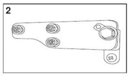
natural_image
Technical line drawing of a mechanical bracket with four circular components and mounting holes (no text or symbols)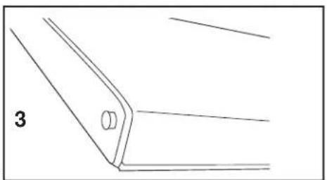
natural_image
Pure technical line drawing of a mechanical bracket or bracket (no text or symbols)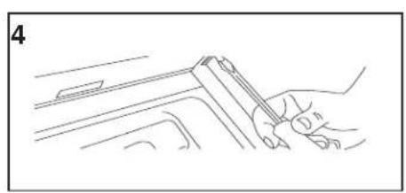
natural_image
Line drawing of a hand using a tool to cut or mark a component on a surface (no text or symbols)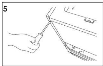
natural_image
Line drawing of a hand using a tool to lift or adjust a mechanical component (no text or symbols present)
natural_image
Line drawing of a hand using a tool to lift a mechanical component (no text or symbols)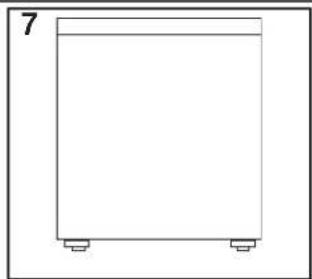
natural_image
Simple line drawing of a rectangular container with two side legs and a top handle, labeled with the number 7 (no text or symbols on the container itself)NETTOYAGE DE VOTRE GLACIÈRE DE BIÈRE PRESSION
Danby Products Limited
PO Box 1778, Guelph, Ontario, Canada N1H 6Z9
natural_image
Simple black-and-white icon of a telephone handset inside a circle (no text or symbols)1-800-26-Danby
(1-800-263-2629)

ANTES DE USAR SU EQUIPO PARA SERVIR CERVEZA
natural_image
Person handling a transparent container with mechanical components (no visible text or symbols)
natural_image
Industrial gas supply unit with pressure gauges and tubing (no visible text or labels)natural_image
Industrial piping system with pressure gauge and valve (no visible text or labels)natural_image
Large metallic cylindrical container with a label, placed indoors near a window (no visible text or symbols)natural_image
Line drawing of a hand pressing down on a mechanical component (no text or symbols)natural_image
Line drawing of a hand holding a tool over a pipe fitting (no text or symbols)CÓMO SERVIR LA CERVEZA
natural_image
Technical line drawing of a mechanical assembly with no visible text or symbols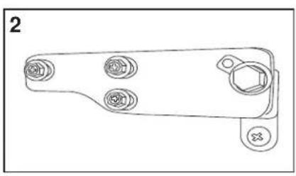
natural_image
Technical line drawing of a mechanical bracket with four circular components and a hexagonal end (no text or symbols)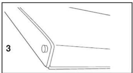
natural_image
Pure technical line drawing of a mechanical bracket or bracket (no text or symbols)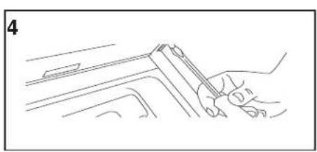
natural_image
Line drawing of a hand holding a pen, poised to write on a surface (no text or symbols present)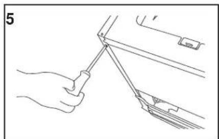
natural_image
Line drawing of a hand using a tool to lift or adjust a mechanical component (no text or symbols present)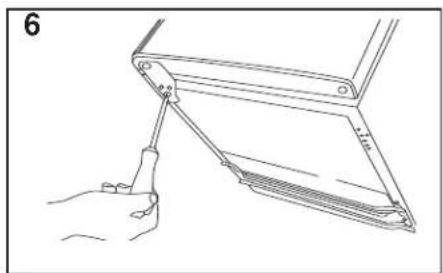
natural_image
Line drawing of a hand holding a tool interacting with a mechanical device (no text or symbols)
natural_image
Simple line drawing of a rectangular container with two side supports (no text or symbols)CÓMO LIMPIAR EL EQUIPO PARA SERVIR CERVEZA
Danby Products Limited
PO Box 1778, Guelph, Ontario, Canada N1H 6Z9
Telephone: (519) 837-0920 FAX: (519) 837-0449
1-800-263-2629
07/13
Danby Products Inc.
PO Box 669, Findlay, Ohio, U.S.A. 45840
Telephone: (419) 425-8627 FAX: (419) 425-8629
KEG COOLER
All repair parts are available for purchase or special order when you visit your nearest service depot. To request service and/or the location of the service depot nearest you, call the TOLL FREE number.
When requesting service or ordering parts, always provide the following information:
- Product Type
- Model Number
- Part Number
- Part Description