
RHI 694 IN - Basket ROSIERES - Free user manual and instructions
Find the device manual for free RHI 694 IN ROSIERES in PDF.
| Brand | Rosieres |
| Model | RHI 694 IN |
| Product type | Cooker hood |
| Version | Extracting (external evacuation) or recirculating (internal recycling) |
| Minimum safety distance (electric cooker) | 60 cm |
| Minimum safety distance (gas/mixed cooker) | 65 cm (or according to cooking appliance instructions if larger) |
| Power supply | See rating label; connection with plug or direct with bipolar switch |
| Max lighting power | 2 halogen lamps 20W max (G4) |
| Grease filter | Metal, dishwasher safe or hand wash (monthly or according to indicator) |
| Activated carbon filter | Washable/regenerable (every 2 months) or disposable (every 3-4 months) |
| Number of speeds | 3 + 1 intensive speed (5 minutes) |
| Controls | Electronic 5-touch or push-button depending on version |
| Filter saturation indicator | Yes (flashing LED, can be enabled/disabled for charcoal) |
| Hood material | Stainless steel (grid U) |
| Weight (estimated) | Approximately 15 kg (not exactly specified) |
| Dimensions (W x D x H approx.) | Width 69 cm, depth 50 cm, adjustable height (depending on installation) |
| Air outlet diameter | 150 mm (standard estimate) |
| Installation | Ceiling (grill) with telescopic chimneys |
| Manufacturer warranty | 2 years (general for Rosieres) |
| Maintenance | External cleaning with damp cloth and mild detergent; do not use alcohol |
| Energy consumption | Energy class not specified (estimated class B-C) |
| Maximum air flow | Approximately 600 m³/h (estimate for this size) |
| Noise level | Approximately 55-65 dB(A) depending on speed |
| Included accessories | Wall plugs, drilling template, screws, deflector for recirculation version (charcoal filter optional) |
Frequently Asked Questions - RHI 694 IN ROSIERES
User questions about RHI 694 IN ROSIERES
0 question about this device. Answer the ones you know or ask your own.
Ask a new question about this device
Download the instructions for your Basket in PDF format for free! Find your manual RHI 694 IN - ROSIERES and take your electronic device back in hand. On this page are published all the documents necessary for the use of your device. RHI 694 IN by ROSIERES.
USER MANUAL RHI 694 IN ROSIERES
natural_image
Five identical black circular icons with vertical lines, arranged horizontally (no text or symbols)Instruction on mounting and use
Consult the designs in the front pages referenced in the text by alphabet letters. Closely follow the instructions set out in this manual. All responsibility, for any eventual inconveniences, damages or fires caused by not complying with the instructions in this manual, is declined.
Use
The hood is designed to be utilized either for suction version at external evacuation or filtering version at internal recirculation.
Ducting version
The hood is equipped with a top air outlet B for discharge of fumes to the outside (exhaust pipe and pipe fixing clamps not provided). Filter version
Should it not be possible to discharge cooking fumes and vapour to the outside, the hood can be used in the filter version, fitting an activated carbon filter and the deflector F on the support (bracket) G, fumes and vapours are recycled through the top grille H by means of an exhaust pipe connected to the top air outlet B and the connection ring mounted on the deflector F (exhaust pipe and pipe fixing clamps not provided).
To switch from "Vented" to "Ventless" operation, contact your retailer or the manufacturer for the relevant assembly kit.
The models with no suction motor only operate in ducting mode, and must be connected to an external suction device (not supplied).
Installation
The minimum distance between the supporting surface for the cooking vessels on the hob and the lowest part of the range hood must be not less than 60cm from electric cookers and 65cm from gas or mixed cookers.
If the instructions for installation for the gas hob specify a greater distance, this must be adhered to.
Electrical connection
The electrical tension must correspond to the tension noted on the label placed inside the cooker hood. Connect the electrical plug, where provided, to the an easily accessible outlet in conformity with local standards in force. Where an electrical plug is not provided (for direct connection to electrical network) place a standards approved bipolar switch with an aperture distance of not less than 3mm (accessible) from the contacts.
Attention: substituting the supply cable must be carried out by the authorised technical assistance service.
Mounting
Expansion wall plugs are provided to secure the hood to most types of walls/ceilings. However, a qualified technician must verify suitability of the materials in accordance with the type of wall/ceiling. The wall/ceiling must be strong enough to take the weight of the hood. Do not tile, grout or silicone this appliance to the wall. Surface mounting only.
For transportation reasons the upper flue and the lattice girder are temporarily fixed together with two screws A (fig. 5). These must be removed and conserved.
Attention! This product envisages a series of installation operations involving special electric cable connections. Always check during installation that the passage of these cables avoids any possible damage to them:
- Before attaching the hood to the ceiling you need to decide whether to use the hood in the filtering or suction version.
The following operations need to be carried out if you choose the filtering version:
Mount one of the supplied connection rings on deflector F (Fig. 6) (in any case, the one without non-return fumes valve, when this is supplied) with two screws.
Note: Mount the connection ring so that the circular hole is central with respect to the deflector.
Mount deflector F on the upper brackets of the lattice girder with 4 screws.
- Remove the 2 C screws (Fig. 1) that temporarily fix the two parts of the lattice girder together.
Adjust the extension of lattice girder "L", according to the following formula:
L = h - (d+44cm)
Where:
L = lattice girder extension,
h = distance between the ceiling and the support surfaces of the cooking device containers.
d= distance between the lower park of the hood and the support surfaces of the cooking device containers.
Attention! RESPECT THE MINIMUM DISTANCES INDICATED IN THIS INSTRUCTIONS BOOKLET.
Fix the lattice girder with the 8 D screws (Fig. 1).
- Place supplied template E (Fig. 1) onto the ceiling and make the holes indicated and also prepare the area for electrical connection. The side with the arrow on the template corresponds to the front part of the hood (commands side).
For the suction version only: make the outlet for the discharge tube and install a tube of sufficient length to reach the connection ring on the hood motor, when this is installed. Insert 4 dowels.
- Mount the lattice girder onto the ceiling and fix with 4
screws and washers I (Fig. 1).
Attention! The lattice girder has a side: the front is the part without the hooking fold (see also Fig. 1).
- Mount the B connection ring (Fig. 1), with the non-return fumes valve (when supplied) onto the motor housing with two screws.
Note: Mount the connection ring so that the circular hole is central with respect to the motor housing.
-
Filtering version only: install a section of a tube, long enough to reach the connection ring on the motor housing (Fig.1), onto the F deflector.
-
Mount motor housing J (Fig. 1) to the lattice girder with 4 large S screws (Fig. 3) so that the side with the electronic and connection boxes are on the front part.
-
Connect the discharge tube.
-
Fix bracket K (Fig. 3-Fig. 4-Fig. 4.1), which supports the electronic box and the connection box, to the motor housing with 2 screws.
-
Insert the M commands box into apposite N sealing rail (Fig. 4.2 - Fig. 4.3).
Note! The drawing shows a type of commands box. This can be equipped with a number of different keys and leds depending on the model possessed.
-
Connect to the domestic electric power.
-
Mount upper flue O onto the lattice girder with the 2 A screws (Fig. 5).
Note: the upper flue is reversible. It is possible to install it with air exit slit H (Fig. 5) upward (filtering version) or downward (suction version) so as to be hidden when the lower flue is mounted (in this case, however, the total extension of the flues will be reduced).
Attention! Insert the flue carefully so as to avoid damaging the electric cables and the commands box.
- Mount lower flue P and fix it to the lower part of the motor housing with two screws Q (Fig. 5)
Note: Do not tighten completely!
Attention! Insert the flue carefully so as not to avoid damaging the electric cables and the commands box.
- Remove the carbon filter holding frame and tighten internal screw R (Fig. 4.3) that adjusts the position of the commands box so that the keys extrude from the flue.
Block the position tightening the lock nut on the screw.
-
Mount spacer ring S (Fig. 5) or the mantel, when envisaged.
-
Remove central screw T (Fig. 5), placed between the bulbs, temporarily and fix filter holder mask U (Fig. 5) with it.
-
Tighten screwsQ (Fig. 5) with decision.
Operation
Use the high suction speed in cases of concentrated kitchen vapours. It is recommended that the cooker hood suction is switched on for 5 minutes prior to cooking and to leave in operation during cooking and for another 15 minutes approximately after terminating cooking.
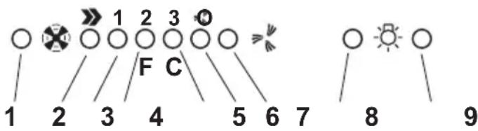
Functioning - 5-key electronic model
-
Motor OFF button
-
ON button and motor speed selection button 1 - 2 - 3 - 1 - 2 - ....
-
Speed 1 LED
-
Speed 2 LED and metal grease filter saturation LED (in this latter case, the LED will flash - See instructions on grease filter cleaning).
Once the grease filters have been cleaned, press button 1 for about 3 seconds until you hear the acoustic signal (beep): the LED 4 will now stop flashing.
- Speed 3 LED and active carbon filter saturation LED (in this latter case, the LED will flash - See instructions on active carbon filter replacement).
Once you have replaced the charcoal filter, press button 1 for about 3 seconds until you hear the acoustic signal (beep). LED 5 will now stop flashing. Warning!
The active carbon filter saturation LED is not activated.
In order to activate the active carbon filter saturation indicator, press buttons 2 and 7 simultaneously for 3 seconds. Initially, only LED 4 will flash, then after the 3 seconds have passed, LED 5 will also start flashing, indicating that the active carbon filter saturation control system is active.
To switch off the system, re-press the same two buttons: after 3 seconds LED 5 will stop flashing and the device will be switched off.
-
Intensive speed LED
-
Intensive speed ON switch
This speed should be used when the concentration of cooking fumes or odours is particularly strong (for example when frying, cooking fish etc.).
The fast speed will run for about 5 minutes and then return to the speed previously set automatically (1, 2 or 3), or switch off if no speed was selected.
To turn off the fast speed, before the end of the 5 minutes, press button 1 or button 2.
-
OFF lamp button
-
ON lamp button
If the hood fails to operate correctly, briefly disconnect it from the mains power supply for almost 5 sec. by pulling out the plug. Then plug it in again and try once more before contacting the Technical Assistance Service.
Model with button panel
DCBAE
natural_image
Five identical black circular icons with vertical lines, arranged horizontally (no text or symbols)A. on/off light switch
B. on/off aspiration switch and minimum power selection
B+C. medium power selection aspiration switch
B+D. maximum power selection aspiration switch
E. operating gauge (foreseen in the model with round buttons)
Maintenance
Prior to any maintenance operation ensure that the cooker hood is disconnected from the power supply.
Cleaning
The cooker hood should be cleaned regularly internally and externally. Clean using the cloth dampened with neutral liquid detergent. Do not use abrasive products.
DO NOT USE ALCOHOL!
Warning: Failure to carry out the basic standards of the cleaning of the cooker hood and replacement of the filters may cause fire risks.
Therefore we recommend observing these instructions.
Grease filter
Fig. 5
This must be cleaned once a month (or when the filter saturation indication system – if envisaged on the model in possession – indicates this necessity) using non aggressive detergents, either by hand or in the dishwasher, which must be set to a low temperature and a short cycle. When washed in a dishwasher, the grease filter may discolour slightly, but this does not affect its filtering capacity.
Remove the stainless steel grid "U", by unscrewing knob "T".
Charcoal filter (filter version only)
Fig. 7
It absorbs unpleasant odours caused by cooking.
The charcoal filter can be washed once every two months (or when the filter saturation indication system – if envisaged on the model in possession – indicates this necessity) using hot water and a suitable detergent, or in a dishwasher at 65^ C (if the dishwasher is used, select the full cycle function and leave dishes out).
Eliminate excess water without damaging the filter, then remove the mattress located inside the plastic frame and put it in the oven for 10 minutes at 100^ C to dry completely. Replace the mattress every 3 years and when the cloth is damaged. Remove the filter holder frame by turning the knobs (g) 90^ that affix the chimney to the cooker hood.
Insert the pad (i) of activated carbon into the frame (h) and fit the whole back into its housing (j).
It is possible to use a traditional carbon filter, neither washable nor regenerable, to be replaced every 3 - 4 months.
The filter holder frame of the carbon filter is welded together; the eventual frame supplied with the hood is not, therefore, to be used.
Insert it into its housing and fix it turning the 2 plastic knobs.
Replacing lamps
Fig. 2
Disconnect the hood from the electricity.
Warning! Prior to touching the light bulbs ensure they are cooled down.
- Unscrew the lamp cover.
- Replace the damaged light bulb.
Only use halogen bulbs of 20W max (G4), making sure you do not touch them with your hands.
- Refit the lamp cover.
If the lights do not work, make sure that the lamps are fitted properly into their housings before you call for technical assistance.
Caution
Never use the hood without the grill mounted!
This appliance is designed to be operated by adults. Children should not be allowed to tamper with the controls or play with the appliance.
The premises must have sufficient ventilation when the kitchen hood is used at the same time as other apparatuses that use gas and other fuels.
The sucked air must not be conveyed in a conduit used for discharging fumes produced by apparatuses fuelled by gas or other fuels.
Cooking food on the flame under the hood is severely prohibited.
The use of open flame damages the filters and can cause a fire; it must therefore be avoided in any case.
Frying must be carried out under control in order to prevent overheated oil catching fire.
Keep strictly to the regulations envisaged by the competent local authority as far as the technical and safety measures to adopt for discharging fumes are concerned.
The hood is to be cleaned frequently both internally and externally.
Failure to observe the regulations about cleaning the hood and substituting and cleaning the filters can lead to the risk of fire.
Any responsibility is declined for possible inconveniences, damage or fire caused to the apparatus deriving from failure to observe the instructions shown in this manual.
This appliance is marked according to the European directive 2002/96/EC on Waste Electrical and Electronic Equipment (WEEE). By ensuring this product is disposed of correctly, you will help prevent potential negative consequences for the environment and human health, which could otherwise be caused by inappropriate waste handling of this product.
The symbol ■ on the product, or on the documents accompanying the product, indicates that this appliance may not be treated as household waste. Instead it shall be handed over to the applicable collection point for the recycling of electrical and electronic equipment. Disposal must be carried out in accordance with local environmental regulations for waste disposal.
For more detailed information about treatment, recovery and recycling of this product, please contact your local city office, your household waste disposal service or the shop where you purchased the product.
natural_image
Five identical black circular icons with vertical rods, arranged horizontally (no text or symbols)natural_image
Five identical black circular icons with vertical lines, arranged horizontally (no text or symbols)natural_image
Five identical black circular icons with vertical lines, arranged horizontally (no text or symbols)
- Instruction on mounting and use
- Use
- Ducting version
- Installation
- Electrical connection
- Mounting
- Operation
- Functioning - 5-key electronic model
- Model with button panel
- DCBAE
- Maintenance
- Cleaning
- DO NOT USE ALCOHOL!
- Grease filter
- Fig. 5
- Charcoal filter (filter version only)
- Fig. 7
- Replacing lamps
- Fig. 2
- Caution
Brand : ROSIERES
Model : RHI 694 IN
Category : Basket