
Virus Race 4.1 - Remote control toy Carson - Free user manual and instructions
Find the device manual for free Virus Race 4.1 Carson in PDF.
| Product type | Radio-controlled racing vehicle |
| Brand | Carson |
| Model | Virus Race 4.1 |
| Category | Radio-controlled toy |
| Power supply | Rechargeable LiPo battery |
| Remote control | 2.4 GHz radio control |
| Motor | Electric motor |
| Steering | Steering servo |
| Functions | Forward/reverse, left/right |
| Range | Approx. 100 m |
| Battery | LiPo (included), capacity not specified |
| Charging time | Approx. 1 hour 30 minutes |
| Running time | Approx. 20 minutes |
| Weight | Approx. 1.5 kg |
| Dimensions (L x W x H) | Approx. 40 x 25 x 15 cm |
| Recommended age | From 14 years (adult supervision) |
| Use | Suitable terrain, off public roads |
| Maintenance | Clean after use, check screws and connections |
| Safety | Do not use in rain, do not touch hot parts, follow LiPo guidelines |
| Spare parts | Original Carson parts available |
| Compliance | Directive 2014/53/EU |
| Warranty | Manufacturer's warranty against manufacturing defects |
Frequently Asked Questions - Virus Race 4.1 Carson
User questions about Virus Race 4.1 Carson
0 question about this device. Answer the ones you know or ask your own.
Ask a new question about this device
Download the instructions for your Remote control toy in PDF format for free! Find your manual Virus Race 4.1 - Carson and take your electronic device back in hand. On this page are published all the documents necessary for the use of your device. Virus Race 4.1 by Carson.
USER MANUAL Virus Race 4.1 Carson
Before using your product for the first time or ordering any spare parts, check that your manual is fully up-to-date. This manual contains the technical appendices, important instructions for correct start-up and use and product information, all fully up-to-
date before going to press. The contents of this manual and the technical data of the product can change without prior notice.
For the latest version of your manual, see: www.carson-modelsport.com
FR // Remarque importante
natural_image
Four identical cylindrical batteries with plus and minus signs, arranged horizontally (no text or symbols beyond the plus/minus signs)natural_image
Simple line drawing of a rectangular object with three horizontal lines extending from its right side, resembling a connector or cable (no text or symbols)natural_image
Line drawing of a hand using a tool to cut a car wheel (no text or symbols)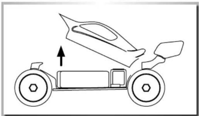
natural_image
Line drawing of a car with an arrow indicating upward motion, no text or symbols presentAUFLADEN DES FAHRAKKUS
ACHTUNG!
natural_image
Simple line drawing of a battery connected to a light bulb, no text or symbols presentEINLEGEN DER FAHRAKKUS
natural_image
Line drawing of a hand using a tool to adjust or install a vehicle chassis (no text or symbols visible)natural_image
Illustration of two hands assembling a small electronic component (no text or symbols visible)STEUERN DES MODELLS
natural_image
Diagram of a vehicle showing front wheel, rear wheel, and side truss (no text or symbols)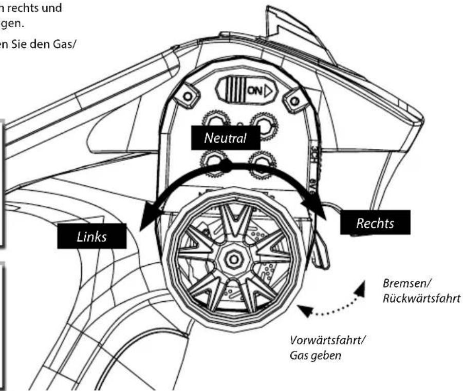
We congratulate you for buying this CARSON product, which is designed and manufactured using state of the art technology.
According to our policy of continued development and product improvement we reserve the right to make changes in specifications regarding equipment, material and design at any time without notice.
Specifications or designs of the actual product may vary from those shown in this manual or on the box.
The manual forms part of this product. Should you ignore the operating and safety instructions, the warranty will be void.
Keep this guide for future reference.
Limited Warranty
This product is warranted by CARSON against manufacturing defects in materials and workmanship under normal use for 24 months from the date of purchase from authorised franchisees and dealers. In the event of a product defect during the warranty period, return the product along with your receipt as proof of purchase to any CARSON store.
CARSON will, at its option, unless otherwise provided by law:
(a) Correct the defect by repairing the product without charging for parts and labour;
(b) Replace the product with one of the same or similar design.
All replacement parts and products, and products on which a refund is made, become the property of CARSON. New or reconditioned parts and products may be used in the performance of warranty services.
Repaired or replaced parts and products are warranted for the remainder of the original warranty period. You will be charged for repair or replacement of the product made after the expiration of the warranty period.
The Warranty does not cover:
- Damage or failure caused by or attributable to acts of God, abuse, accident, misuse, improper or abnormal usage, failure to follow instructions, improper installation or maintenance, alteration, lightning or other incidence of excess voltage or current;
- Damage caused by losing control of your model;
- Any repairs other than those provided by a CARSON authorised service facility;
- Consumables such as fuses or batteries;
- Cosmetic damage;
- Transportation, shipping or insurance costs; or
- Costs of product removal, installation, set-up service adjustment or reinstallation;
- Any changes to plugs and cables, open the housing and damage the sticker.
This warranty gives you specific legal rights, and you may also have other rights which may vary according to the country of purchase.
Declaration of conformity
TAMIYA-CARSON Modellbau GmbH & Co. KG hereby declares that the radio equipment type 500409023/500409024 conforms to Directive 2014/53/EU. The complete text for the EU declaration of conformity is available at the following Internet address.
The explanation of the symbol on the product, packaging or instructions: Electronic devices are valuable products and should not be disposed of with the household waste when they reach the end of their service life! Help us to protect the environment and respect our resources by delivering this appliance to the relevant recycling point.

We wish you a lots of fun using your CARSON product!
Before use, read this manual carefully!
CONTENTS
Preface ....17
Included Items Accessories....18
Safety Precautions....19
Safety Precautions lithium batteries....20
Chassis....21
Removing the Body 21
Charge battery pack....22
Inserting the drive batteries 22
Turn on the RC System....23
How to Control Your Model....23
Troubleshooting 24
ESC - Features....25
ESC - Connection/Cabling 25
ESC - Basic Settings....26
Throttle Range Explanation 27
Program the ESC....28
Program the ESC with the Set Button 29
ESC - Connecting Program Card....30
ESC - Trouble Shooting....30
Assembly instructions ....43
Spare Parts 62
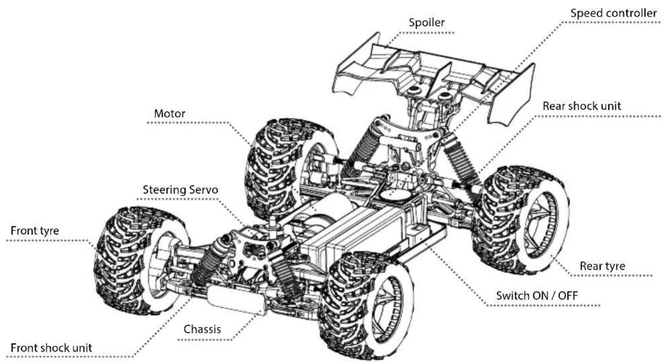
INCLUDED ITEMS ACCESSORIES
natural_image
Four identical cylindrical batteries with one charge and the other empty, arranged side by side (no text or symbols)Batteries
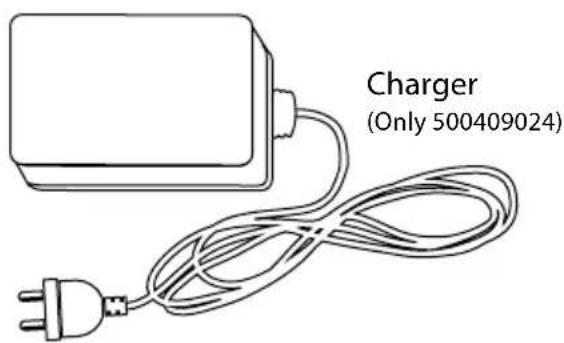
(Only 500409024)
natural_image
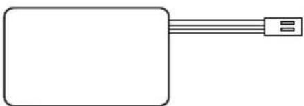
Simple line drawing of a rectangular object with three horizontal lines extending from its top, resembling a connector or cable (no text or symbols)2x Driving battery pack
(Only 500409024)
TECHNICAL DATA
- RC model 1:8 Brushless 4S
- Operating voltage: 4S 14.8 V
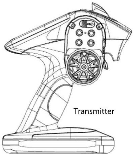
• 2.4 GHz transmitter
• Transmitter operating voltage: 4.8-6V
- Modulation: F.H.S.S.
• Maximum transmitter output: 100 mW
SAFETY PRECAUTIONS
Safety Instructions and Intended Use
This product is designed exclusively for hobby use and may only be used on tracks and areas intended for this purpose.
No persons or animals may be transported with this model.
To avoid operator errors, it is mandatory that the user manual is read before use!
These models may only be used with bodywork that is correctly fitted.
When removing the bodywork, please note that, during operation, certain parts can become very hot.
Please note that various models can generate very high noise levels and should, therefore, not be operated in your immediate proximity.
Please make sure, before every driving session, that the tank is correctly closed or the power pack is correctly inserted.
To avoid faulty operation of the control system causing the model to run out of control, it must be checked that the transmitter and model batteries are in good condition.
It is essential to check that the model is correctly assembled both before and after use; if need be, tighten nuts and bolts.
This model is not a toy!
- This product is not a toy, its operation must be learned step by step.
- Children under 14 years of age should operate the model only if supervised by an adult.
Operating RC models is a fascinating hobby that, however, must only be exercised with proper precautions and care. Since the weight of this model is considerable and it can reach a very high speed it can, if it runs out of control, cause significant damage and injury for which you, as the operator, are liable.
Only a correctly assembled model will work and react as expected. Never improvise with unsuitable materials but, when the need arises, use only original spare parts. Even if the model is pre-assembled, all joints and fastenings should be checked for correct seating and tightness.
Before use, you must make sure of the following points:
- All rechargeable batteries must be fully charged.
• Before starting, check the radio range.
- Check that the model reacts correctly to the control signals.
- All functional parts of the product are in a faultless condition and have been checked.
- All screw fastenings are firmly seated.
- Do not drive under high-voltage power lines or radio masts or with nearby thunderstorms!
- Atmospheric interference can influence the operation of your model.
- The electrical parts of the model are not water-tight. Do not, therefore, drive it in rain or snow or through puddles or wet grass.
- The remote controlled model may be driven only on suitable areas and must not be used on the public highway.
• Do not use near people or animals!
- Do not use it when tired or if your reactions are otherwise impaired.
• Always maintain direct visual contact with your model.
- Regular maintenance and care are required for first class driving performance.
- The model has parts that become hot in operation, e.g. the top of the motor, the metal gearbox, amongst many others. Touching these parts during operation can cause injury.
Pay attention to the charge level indication on your transmitter.
- With power packs or batteries that are half discharged, you can lose control of the model.
- In the transmitter, never mix fully charged batteries, rechargeable or not, with half discharged batteries or rechargeable batteries of different capacity.
- Never try to charge non-rechargeable batteries (dry cells), only batteries specified as rechargeable can be charged.
SAFETY PRECAUTIONS LITHIUM BATTERIES
1. General
Lithium batteries (accumulators) are energy storage devices with a high energy density and can present risks. For this reason, particular care is needed when charging, discharging, storing and handling.
Read these instructions very carefully before first using the battery. Do not fail to take note of the warning notices and instructions for use.
Misuse can lead to risks such as explosion, overheating or fire.
Failure to observe the instructions for use leads to early failure and other defects.
The instructions should therefore be kept in a safe place and it is essential that they are handed over to the second user if the batteries are passed on.
2. Warning notices
- Avoid short-circuits. A short-circuit may well destroy the product. Cables and connections must be well insulated.
- It is essential when connecting the battery to ensure that the polarity is correct.
- Original plug connectors and cables may not be cut off or changed - if need be, use an adapter cable.
- Do not expose the battery to excessive heat or cold or to direct sunlight. Do not throw in the fire. Do not place the battery in contact with water or other liquids.
- Charge the battery only with charging units intended for the purpose and always use the balancer connection. It is only by using the balancer connection that optimum charging can be ensured. If this connection is not used, charging is subject to the risks mentioned above. Before charging, always first allow the battery to cool to ambient temperature. Never charge while hot.
- When charging, place the battery on a non-flammable, heat-resistant support. There should be no flammable or readily ignited objects in the vicinity of the battery.
- During charging or operation, never leave the battery unsupervised.
- Do not fail to keep to the recommended charge/discharge current.
- The battery casing must not be damaged. It is essential to avoid damage by sharp objects such as knives or the like, from dropping, impact, bending etc. Damaged batteries may no longer be used.
- Batteries are not toys. They should be kept away from children.
3. Charging instructions
Lithium batteries are charged according to the CC-CV procedure. CC stands for "constant current", which is applied during the first phase of charging. Once the battery reaches the maximum voltage configured in the charger, it switches to CV (constant voltage) for the second phase of charging. The battery voltage no longer increases. The charging current now falls continuously until the battery is fully charged. The maximum charging current for the battery is 1C (C=nominal capacity of the battery, e.g. for a battery with a nominal capacity of 2700 mA, the maximum charging current for the battery is 2700 mA (2.7 A)). Never charge several batteries together from a single charger. Differing states of charge and capacities can lead to overcharging and destruction.
4. Storage instructions
Lithium batteries should be stored charged to 20-50 % of their capacity and at a temperature of 15-18 °C. If the cell voltage falls below 3 V, they should be recharged. Deep discharge and storage when discharged (call voltage <3 V) will render the battery unusable.
5. General terms of guarantee
There is a legal guarantee for production and material faults as applicable at the time of dispatch. No liability is accepted for normal wear and tear. This guarantee does not apply for defects attributable to improper use, inadequate maintenance, third-party interference or mechanical damage. This applies, in particular, to used batteries and batteries clearly showing signs of use.
Damage and loss of performance due to improper handling and/or overload are not product faults. Batteries are consumables and subject to a certain ageing. This is influenced by factors such as the charge/discharge currents, the charging procedure, the operating and storage temperatures and the state of charge during storage. The ageing shows itself in, among other things, an irreversible loss of capacity. In the model field, where batteries are frequently used to supply motors, very high currents can flow from time to time.
6. Exclusion of liability
Since we are unable to have any control over charge/discharge, handling, compliance with assembly and operating instructions, battery replacement and its care and maintenance, Tamiya / Carson can accept no liability for loss, damage or costs incurred.
Any claim for damages that may result from operation, failure or faulty operation or that is in any way related thereto will therefore be refused. We accept no liability for personal injury or material damage and their consequences that arise from our delivery.
7.Disposal instructions
Batteries are hazardous waste. Damaged or unusable cells must be disposed of in the correct manner.
No liability for printing errors, we reserve the right to make changes!
CHASSIS
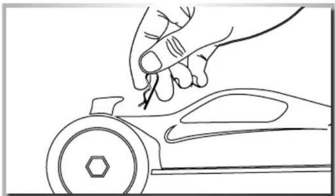
REMOVING THE BODY
- Remove hook pin • To remove the body - swing to open
natural_image
Line drawing of a hand using a tool to cut a car wheel (no text or symbols)
natural_image
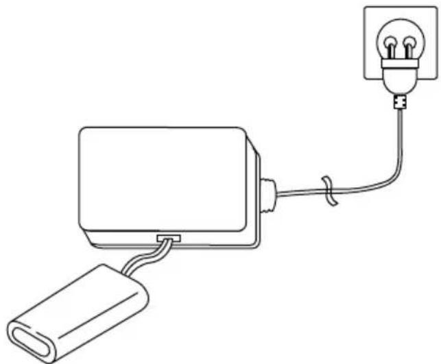
Line drawing of a car with an arrow indicating upward motion, no text or symbols presentCHARGE BATTERY PACK
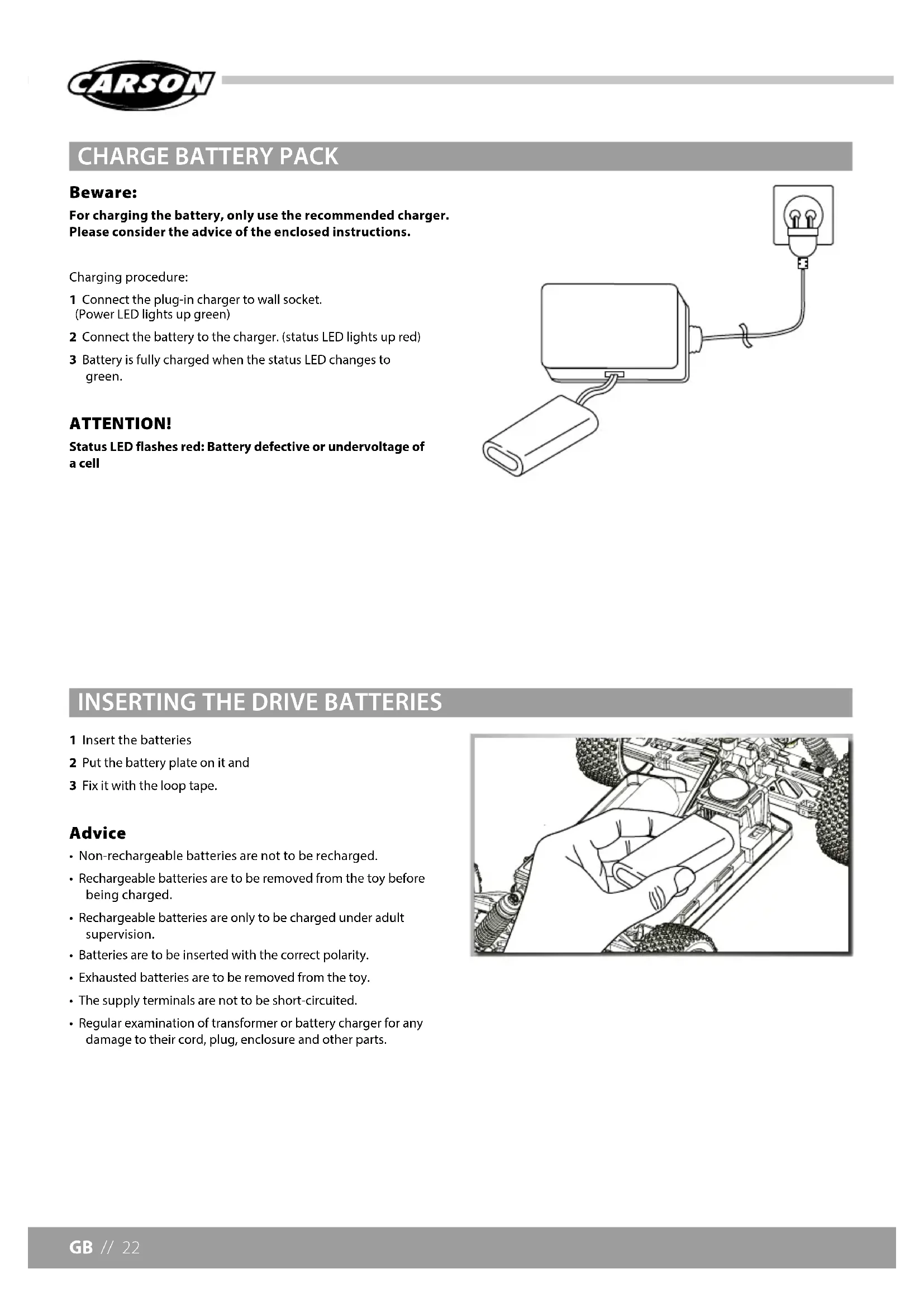
Beware:
For charging the battery, only use the recommended charger. Please consider the advice of the enclosed instructions.
Charging procedure:
1 Connect the plug-in charger to wall socket.
(Power LED lights up green)
2 Connect the battery to the charger. (status LED lights up red)
3 Battery is fully charged when the status LED changes to green.
ATTENTION!
Status LED flashes red: Battery defective or undervoltage of a cell
natural_image
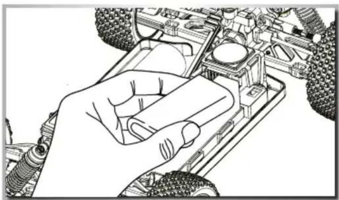
Simple line drawing of a bulb connected to a battery and cable (no text or symbols)INSERTING THE DRIVE BATTERIES
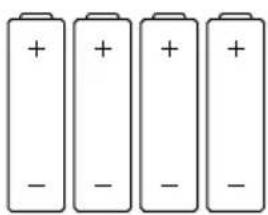
1 Insert the batteries
2 Put the battery plate on it and
3 Fix it with the loop tape.
Advice
• Non-rechargeable batteries are not to be recharged.
- Rechargeable batteries are to be removed from the toy before being charged.
- Rechargeable batteries are only to be charged under adult supervision.
- Batteries are to be inserted with the correct polarity.
• Exhausted batteries are to be removed from the toy.
• The supply terminals are not to be short-circuited.
- Regular examination of transformer or battery charger for any damage to their cord, plug, enclosure and other parts.
natural_image
Line drawing of a hand using a tool to adjust or install a vehicle chassis (no text or symbols visible)TURN ON THE RC SYSTEM
CAUTION!
Always turn the transmitter's power switch ON first!
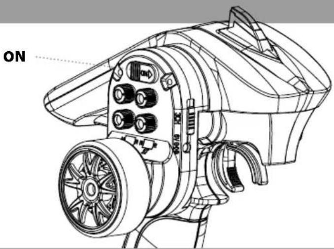
1 Connect the rechargeable battery for the driving.
2 Switch on the receiver.
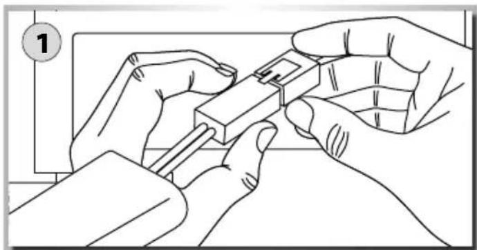
3 Put the body on and fix it with the body split pins.
natural_image
Line drawing of hands assembling a component with pins, no text or symbols presentHOW TO CONTROL YOUR MODEL
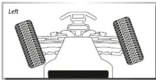
- Raise the tyres off the ground
- Turn the steering wheel to the right and left as far as it will go. The wheels are to follow the steering direction.
- If the wheels operate in the opposite direction, operate the servo Reverse switch (ST in position REV).
• To regulate the driving speed, actuate the throttle/brake - backwards (forward driving, accelerating) or
- forwards (braking, reversing)
natural_image
Diagram of a car's front view showing steering wheel, dashboard, and side-mounted tires (no text or symbols)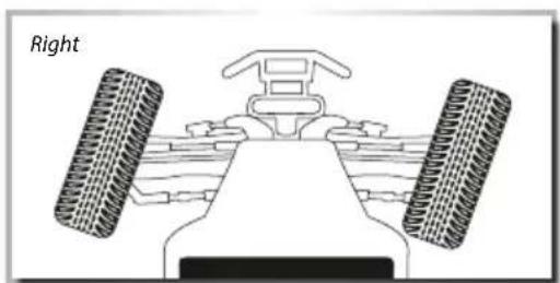
natural_image
Diagram of a vehicle's front view showing two tires and a steering wheel (no text or symbols)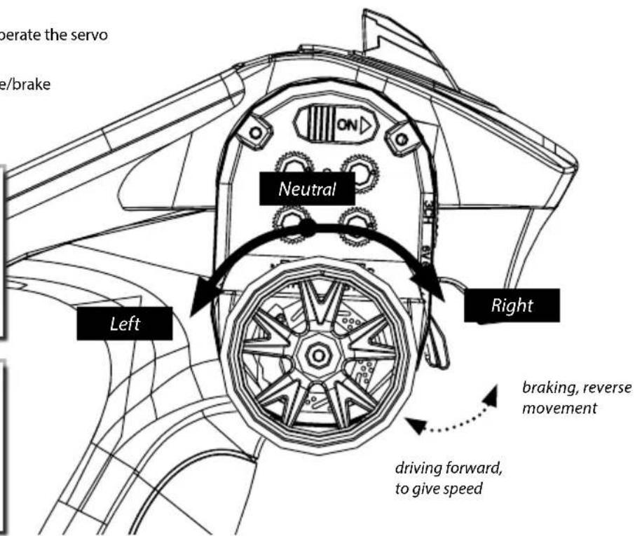
TROUBLESHOOTING
| Problem Cause Correction | ||
| Model doesn’t move Transmitter or chassis power switch is not "ON" | Switch power on receiver or transmitter | |
| Loss of control | Batteries have run down | Change batteries or charge them |
| Doesn’t run straight | Steering trim is not adjusted correctly | Make adjustment |
| Front and rear wheel nuts are too lose Tighten wheel nuts | ||
| Doesn’t stop | Throttle trim is not adjusted correctly | Make adjustment |
| Doesn’t reverse | Throttle trim is not adjusted correctly | Make adjustment |
| Wrong action Control properly | ||
| Running too slowly | Batteries have run down | Change batteries or charge them |
| Motor has lost power Change to spare motor | ||
| Rear wheel nuts are too lose | Tighten wheel nuts | |
| Dust or foreign objects are inside gears | Turn the power switch "OFF" and clean out gears | |
ESC - FEATURES
This speed controller can easily be set for simple operation. After powering up, it automatically searches for the neutral point. At the end of the automatic setup, the motor emits a do-re-mi sound to indicate that the neutral point has been adopted.
- Operating modes: forwards and forwards/backwards
- Proportional brake function with 4 steps of maximum brake force adjustment, 8 steps of drag brake force adjustment
- Various start modes (also called "punch") from "soft" to "aggressive"
- Splash-proof and dustproof.
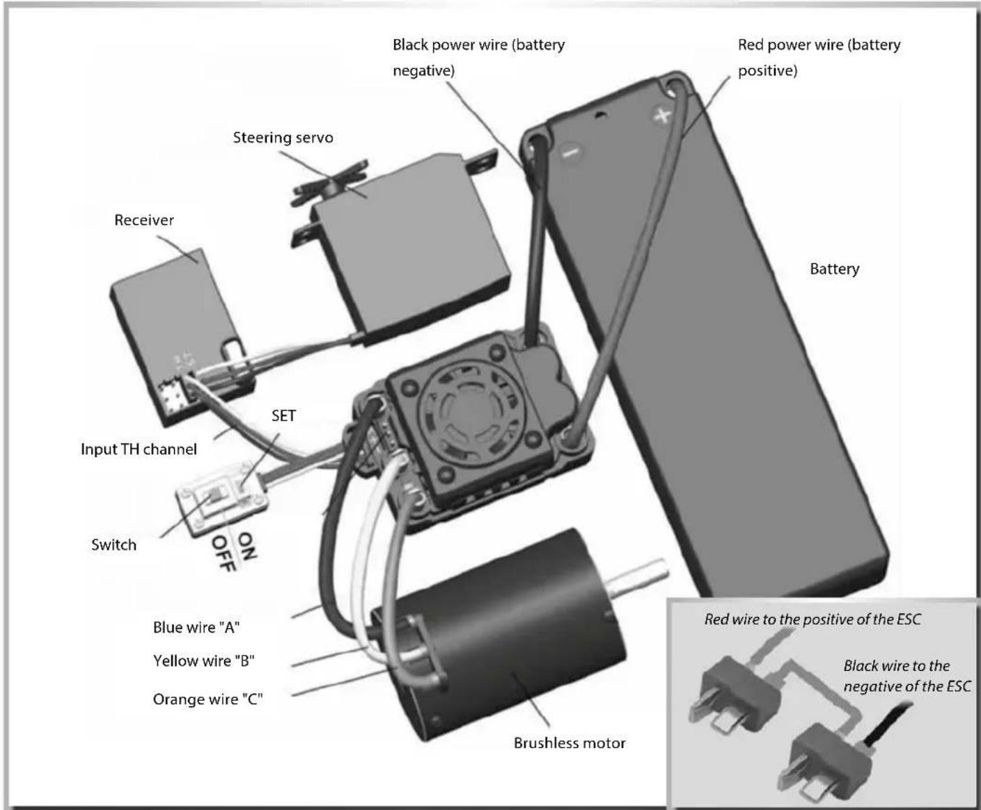
ESC - CONNECTION/CABLING
Connect the ESC, motor, receiver, battery and servo according to the following diagram.
Positive (+) and negative (-) wires of the ESC are connected with the battery pack.
A, B and C are connected with the motor wires. The control cable of
the ESC (wires in black, red and white colour) is connected with the throttle channel of the receiver (usually CH2).
The A, B, C wires of the ESC can be connected with the motor wires freely (without any order).
If the motor runs in the opposite direction, please swap any two wire connections.
ESC - BASIC SETTINGS
Throttle range setting (throttle range calibration)
In order to make the ESC fit the throttle range of your transmitter, you must calibrate it for the following cases; otherwise the ESC cannot work properly.
1) Begin to use a new ESC
2) Begin to use a new transmitter
3) Change the settings of neutral position of the throttle lever, the ATV or EPA parameters, etc.
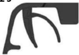
There need to be set 3 points. They are the end point of "forward", the end point of "backward" and the neutral point. The following pictures show how to set the throttle range with your transmitter.
A) Switch off the ESC and turn on the transmitter.
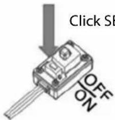
B) Hold the "SETUP"-key of the ESC and then switch on the ESC. Release the "SETUP" key as soon as the red LED begins to flash.
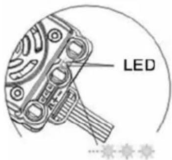
Note 1
The "SET" key of ESC is at the power switch (see picture).
Note 2
If you don't release the "SET" key as soon as the red LED begins to flash, the ESC will enter the program mode. In such case, please switch off the ESC and re-calibrate the throttle range again as described.
Press and hold
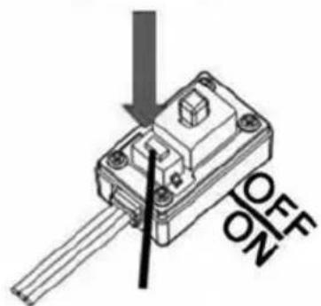
Hold the SET key
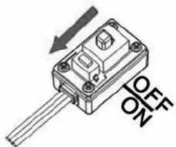
Switch on ESC
Release the SET key as soon as the red LED flashes.
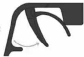
C) Set the 3 points according to the steps.
1. The neutral point
Move the throttle lever at the neutral point, and then click the SET key. The green LED flashes 1 time.
2. The end point of forward direction
Move the throttle lever at the end point of forward direction, and then click the SET key, the green LED flashes 2 times..
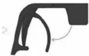
3. The end point of backward direction
Move the throttle lever at the end point of backward direction, and then click the SET key, the green LED flashes 3 times.
The throttle range is calibrated; the motor can be started after 3 seconds.
123
natural_image
Abstract black geometric shape on white background (no text or symbols)Click SET key Click SET key Click SET key
Green LED flashes for 1 time
natural_image
Abstract black curved shape with a rotation arrow, no text or symbols present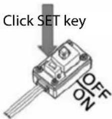
Green LED flashes for 2 times Green LED flashes for 3 times
natural_image
Abstract black curved line drawing with a small arrowhead, no text or symbols present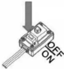
THROTTLE RANGE EXPLANATION
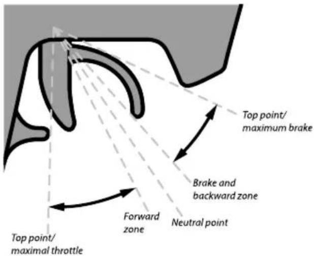
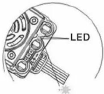
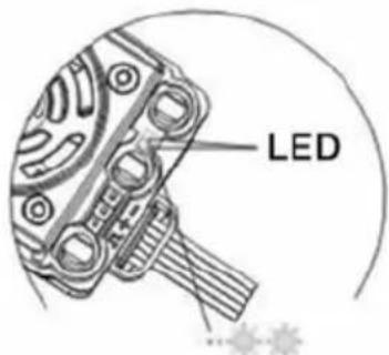
LED status of normal running
- In normal use, if the throttle stick is in the neutral range, neither the red LED nor the green LED lights.
- The red LED lights when the car is running forward or backward and it will flash quickly when the car is braking.
- The green LED lights when the throttle stick is moved to the top point (end point) of the forward zone or backward zone.
Alert tones
- Alert tone input voltage abnormal: The ESC begins to check the input voltage when power on. If it is out of the normal range, such an alert tone will be emitted: "beep-beep-, beep-beep-, beep-beep-" (There is 1 second time interval between every "beep-beep-" tones).
- Alert tone throttle signal abnormal: When the ESC can't detect the normal throttle signal, such an alert tone will be emitted: "beep-, beep-, beep-" (There is 2 seconds time interval between every "beep-" tones).
Protection function
- Low voltage cut-off protection: If the voltage of a lithium battery pack is lower than the threshold for 2 seconds, the ESC will cut of the output power. Please note, that the ESC cannot be restarted if the voltage of one lithium cell is lower than 3.2 V.
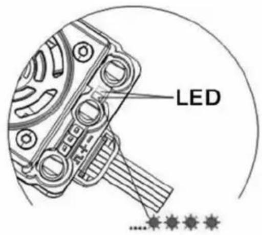
- Over-heat protection: When the temperature of the ESC is over a factory preset threshold for 5 seconds, the ESC will cut off the output power. When the over-heat protection happens, the green LED will flash in such a style: ", * , *, *" (single flash).
- Signal loss protection: The ESC will cut off the output power if the throttle signal is lost for 0.2 second.
PROGRAM THE ESC
1. Programmable items (the italics texts in the form are the default settings)
| Programmable items for Dragster 4S | |||||||||
| Programmable item Programmable value | |||||||||
| 1 2 3 4 | 5 6 7 8 9 | ||||||||
| 1. Running mode Forward | with brake | Forward/ backward with brake | Forward/ backward | ||||||
| 2. Drag brake force in neutral position | 0 % | 5 % | 10 % | 20 % | 40 % | 60 % | 80 % | 100 % | |
| 3. Low voltage cut-off threshold Nonprotection | - | 2.6 V / Zelle | 2.8 V / Zelle | 3.0 V / Zelle | 3.2 V / Zelle | 3.4 V / Zelle | |||
| 4. Start mode (punch) | Level 1 (Soft) | Level 2 | Level 3 | Level 4 | Level 5 | Level 6 | Level 7 | Level 8 | Level 9 (Aggressiv) |
| 5. Maximal brake force | 25 % | 50 % | 75 % | 100 % | |||||
2. Explanation for each programmable item
Running mode
With "Forward with Brake" mode, the car can go forward and brake, but cannot go backward, this mode is suitable for competition.
"Forward/reverse with brake" mode provides backward function, which is suitable for daily training.
But for ESC, "Forward/reverse with brake" mode uses the "Single-click" method to make the car go backward.
"Forward/reverse" mode uses the "Single-click" method to make the car go backward. When you move the throttle lever from forward zone to backward zone, the car will go backward immediately.
Drag brake force in neutral position
Set the amount of drag brake applied at neutral throttle to simulate the slight braking effect of a neutral brushed motor while idle speed.
Low voltage cut-off
The function prevents the lithium battery pack from over discharging. The ESC detects the battery's voltage at any time. If the voltage is lower than the threshold for 2 seconds, the output power will be reduced 70%, 10 seconds later the output will be completely stopped, and the red LED flashes in such a style: “ **, **, **” (double
flashes).
Acceleration mode (also called "Punch")
Select from "Level 1" to "Level 9". A higher number means more aggressive acceleration.
Maximum Brake Force
The ESC provides proportional brake function. The brake force is related to the position of the throttle stick. Maximum brake force refers to the force when the throttle stick is located at the top point of the backward zone. A very large brake force can shorten the brake time, but it may damage the gears.
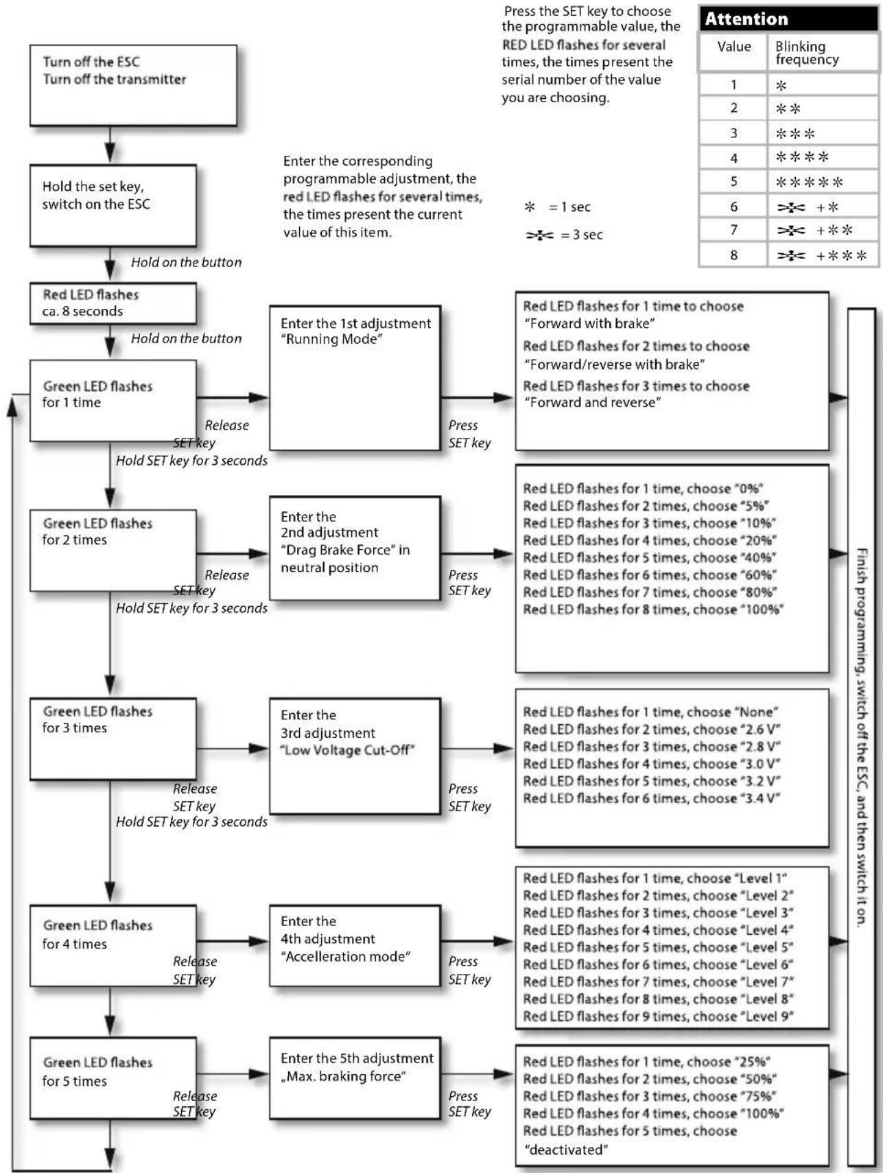
3. Program the ESC with the "SET" button
You'll find the instructions on the next page in the flowchart.
4. Reset all items to default values
At any time when the throttle is located in neutral zone (except in the throttle calibration process or ESC program mode), you can hold the "SET" key for over 3 seconds. The red LED and green LED will flash at the same time, which means each programmable item has be reset to its default value.
PROGRAM THE ESC WITH THE SET BUTTON
The following is a flowchart sample for programming the Dragster S6 controller.
Note:
In the program process, when the LED is flashing, the motor will emit "Beep" tone at the same time.
flowchart
graph TD
    A["Turn off the ESC Turn off the transmitter"] --> B["Hold the set key, switch on the ESC"]
    B --> C["Red LED flashes ca. 8 seconds"]
    C --> D["Green LED flashes for 1 time"]
    D --> E["Enter the 1st adjustment "Running Mode""]
    E --> F["Press SET key"]
    D --> G["Enter the 2nd adjustment "Drag Brake Force" in neutral position"]
    G --> H["Press SET key"]
    D --> I["Green LED flashes for 3 times"]
    I --> J["Enter the 3rd adjustment "Low Voltage Cut-Off""]
    J --> K["Press SET key"]
    I --> L["Green LED flashes for 4 times"]
    L --> M["Enter the 4th adjustment "Acceleration mode""]
    M --> N["Press SET key"]
    L --> O["Green LED flashes for 5 times"]
    O --> P["Enter the 5th adjustment "Max. braking force""]
    P --> Q["Press SET key"]

    style A fill:#f9f,stroke:#333
    style B fill:#f9f,stroke:#333
    style C fill:#f9f,stroke:#333
    style D fill:#ccf,stroke:#333
    style E fill:#ccf,stroke:#333
    style F fill:#ccf,stroke:#333
    style G fill:#ccf,stroke:#333
    style H fill:#ccf,stroke:#333
    style I fill:#ccf,stroke:#333
    style J fill:#ccf,stroke:#333
    style K fill:#ccf,stroke:#333
    style L fill:#ccf,stroke:#333
    style M fill:#ccf,stroke:#333
    style N fill:#ccf,stroke:#333
    style O fill:#ccf,stroke:#333
    style P fill:#ccf,stroke:#333
    style Q fill:#ccf,stroke:#333

    subgraph Flash Settings
        direction TB
        E:::fill=fill;
        F:::fill=fill;
        G:::fill=fill;
        H:::fill=fill;
        I:::fill=fill;
        J:::fill=fill;
        K:::fill=fill;
        L:::fill=fill;
        M:::fill=fill;
        N:::fill=fill;
        O:::fill=fill;
        P:::fill=fill;
        Q:::fill=fill;
        R:::fill=fill;
        S:::fill=fill;
        T:::fill=fill;
        U:::fill=fill;
        V:::fill=fill;
        W:::fill=fill;
        X:::fill=fill;
        Y:::fill=fill;
        Z:::fill=fill;
        AA:::fill=fill;
        AB:::fill=fill;
        AC:::fill=fill;
        AD:::fill=fill;
        AE:::fill=fill;
        AF:::fill=fill;
        AG:::fill=fill;
        AH:::fill=fill;
        AI:::fill=fill;
        AJ:::fill=fill;
        AK:::fill=fill;
        AL:::fill=fill;
        AM:::fill=fill;
        AN:::fill=fill;
        AO:::fill=fill;
        AP:::fill=fill;
        AQ:::fill=fill;
        AR:::fill=fill;
        AS:::fill=fill;
        AT:::fill=fill;
        AU:::fill=fill;
        AV:::fill=fill;
        AW:::fill=fill;
        AX:::fill=fill;
        AY:::fill=fill;
        AZ:::fill=fill;
        BA:::fill=fill;
        BB:::fill=fill;
        BC:::fill=fill;
        BD:::fill=fill;
        BE:::fill=fill;
        BF:::fill=fill;
        BG:::fill=fill;
        BH:::fill=fill;
        BI:::fill=fill;
        BJ:::fill=fill;
        BK:::fill=fill;
        BL:::fill=fill;
        BM:::fill=fill;
        BN:::fill=fill;
        BO:::fill=fill;
        BP:::fill=fill;
        BQ:::fill=fill;
        CA:::fill=fill;
        CB:::fill=fill;
        CC:::fill=fill;
        CD:::fill=fill;
        CE:::fill=fill;
        CF:::fill=fill;
        GG:::fill=fill;
        BH : FalseSet key = FalseSet key = FalseSet key = FalseSet key = FalseSet key = FalseSet key = FalseSet key = FalseSet key = FalseSet key = FalseSet key = FalseSet key = FalseSet key = FalseSet key = FalseSet key = FalseSet key = FalseSet key = FalseSet key = FalseSet key = FalseSet key = FalseSet key = FalseSet key = FalseSet key = FalseSet key = FalseSet key = FalseSet key = FalseSet key
    end

    subgraph Flash Settings (Value)
        direction LR
        A1["1"] *
        A2["2"] **
        A3["3"] ***
        A4["4"] ****
        A5["5"] ******
        A6["6"] >=+ *
        A7["7"] >=+ * *
        A8["8"] >=+ * * *
    end

    subgraph Attention
        direction TB
        B1["0"] Blinking frequency
        B2["1"] *
        B3["2"] **
        B4["3"] ***
        B5["4"] ******
        B6["5"] ******
        B7["6"] >=+ *
        B8["7"] >=+ * *
        B9["8"] >=+ * * *
    end
ESC - CONNECTING PROGRAM CARD
- Remove the fan cable
- Connect programming box with connection
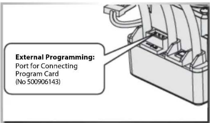
• After completing the programming, reconnect the fans !!!
ESC - TROUBLE SHOOTING
| Trouble Possible reason Solution | ||
| After power on, motor doesn’t work The connections between battery pack and ESC are not correct | Check the power connections Replace the connectors | |
| After power on, motor doesn’t work, but emits “beep-beep-, beep-beep-” alert tones(Every group of “beep-beep-” has a time interval of 1 second) | Input voltage is abnormal, too high or too low | Überprüfen Sie die Einstellung für die BatteCheck the adjustment of the voltage of the battery pack |
| After power on, red LED always lights, the motor doesn’t work | Throttle signal is abnormal Plug the receiver wire into the throttle channel of the receiver correctly | |
| The motor runs in the opposite direction when it is accelerated | The wire connections between ESC and the motor are not correct | Swap any two wire connections between the ESC and the motor |
| The motor suddenly stops running | The throttle signal is lost | Check the transmitter and the receiver |
| The ESC has entered the “Low voltage protection mode” or “Over-heat protection mode” | Red LED flashing means “Low voltage pro - tection”. Please replace battery pack.Green LED flashing means “Over-heat pro - tection”, please stop running to cool the ESC. | |
| When accelerating quickly, the motor stops or trembles | The battery has a bad discharge perfor - mance | Use a better battery |
| The “Start mode (Punch)” of the ESC is too aggressive | Select a softer option for the “Start mode (Punch)” | |
Cher client
natural_image
Technical line drawing of a mechanical assembly with springs and housing components (no text or labels)17. RÄDER • WHEELS
natural_image
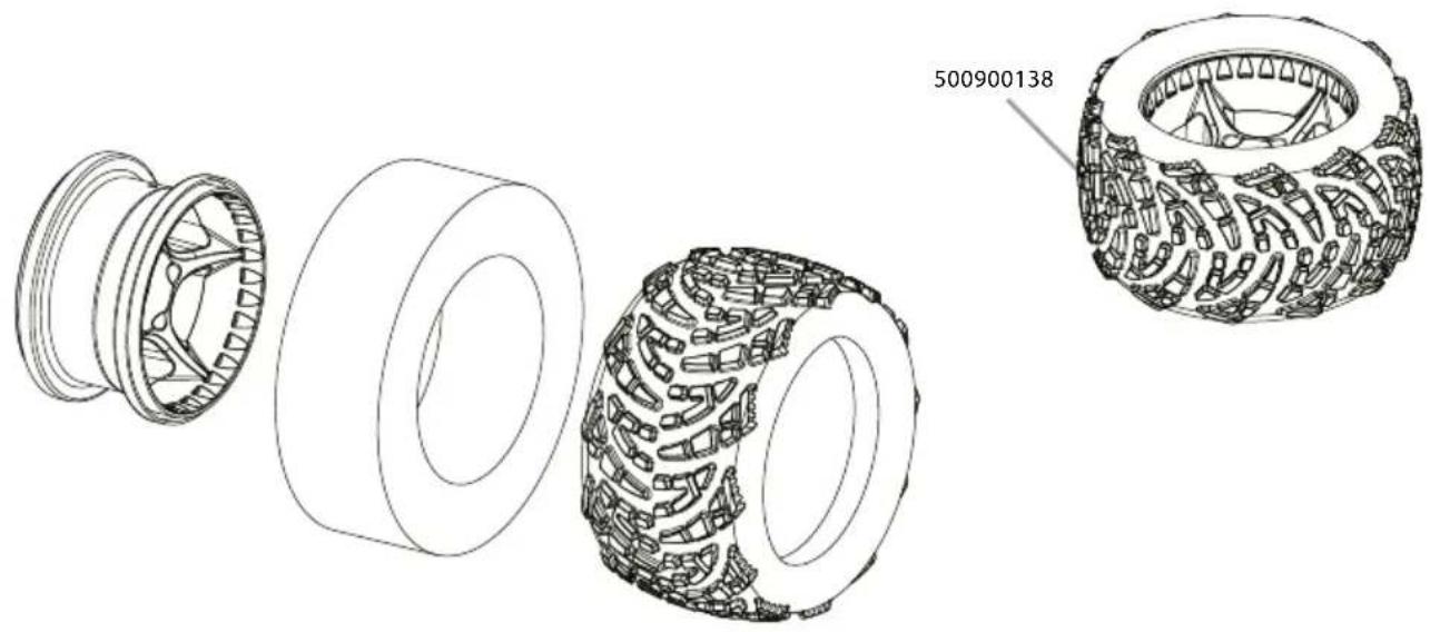
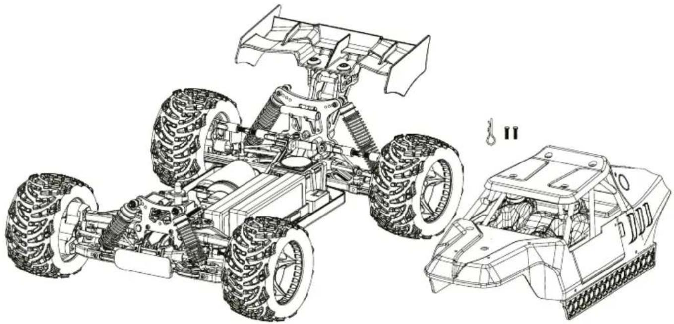
Technical line drawing of a tire assembly showing exploded and assembled views (no text or symbols)18. KAROSSERIE • BODY
natural_image
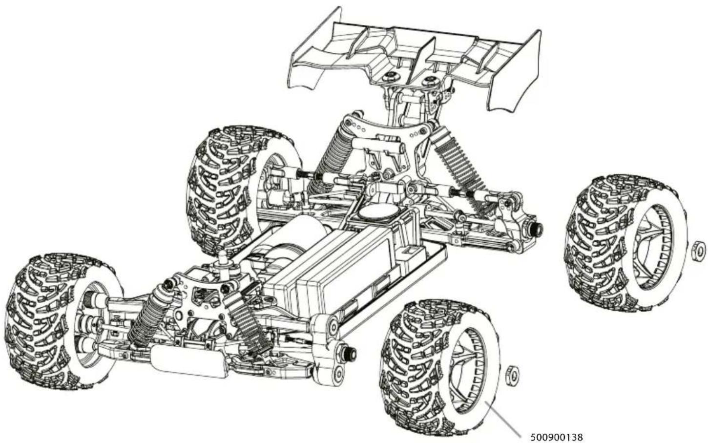
Technical line drawing of a four-wheeled vehicle chassis with visible suspension and tire assembly (no text or symbols)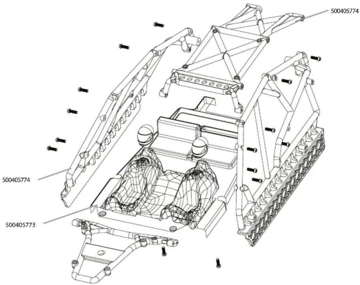
natural_image
Technical line drawing of a two-wheeled vehicle chassis with visible suspension components and structural details (no text or symbols)ERSATZTEILE • SPARE PARTS
500205924 Diff front/rear complete
Diff vorne/hinten komplett

natural_image
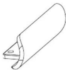
Technical line drawing of a gear and shaft assembly (no text or symbols)500205936 Wing mount posts
Spoilerhalterung
natural_image
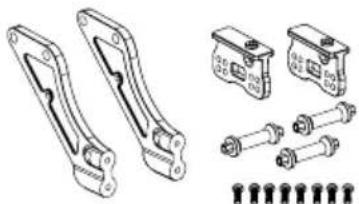
Technical line drawings of mechanical components including brackets, bolts, and housing (no text or symbols)500205942 Front bumper
Frontrammer
natural_image
Simple line drawing of a cylindrical object with a curved handle and a small protrusion (no text or symbols)natural_image
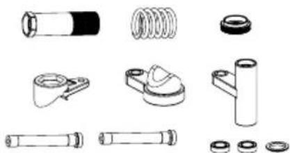
Technical illustration of four different types of mechanical springs and bolts, shown from different angles (no text or labels present)500205943 Servosaver-Unit
Servosaver-Einheit
natural_image
Collection of mechanical components and fittings (no text or symbols visible)natural_image
Technical line drawings of mechanical components (no text or symbols)500205928 Steering set (2)
Lenkhebel vorne (2)
natural_image
Technical line drawing of two mechanical clamping components (no text or symbols)natural_image
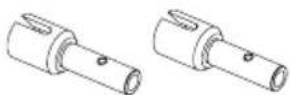
Technical line drawings of two mechanical components (no text or symbols)500205946 Front drive shafts (2)
Kardanwellen vorne (2)
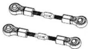
500205929 Steering linkage (2)
Lenkgestänge (2)
natural_image
Two identical mechanical linkages with cylindrical ends and segmented arms (no text or symbols)500205941 Lower suspension mount-kit Querlenkerhalter-Set
natural_image
Pure line drawing of two identical mechanical link components with mounting holes (no text or symbols)ERSATZTEILE • SPARE PARTS
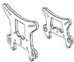
500205948 Shock towers front/rear (2)
Dämpferbrücken v/h (2)
natural_image
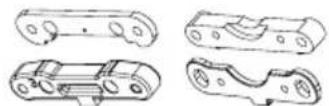
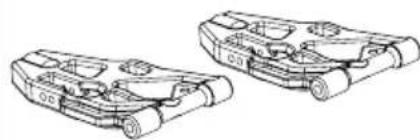
Technical line drawing of two mechanical bracket components (no text or symbols)500205958 Lower arms kit rear (2)
Querlenker-Set unten hi. (2)
natural_image
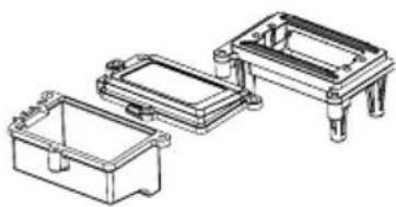
Technical line drawing of two mechanical brackets with mounting holes and circular seals (no text or symbols)500405591 RC-Box/Servomount
RC-Box/Servohalter
natural_image
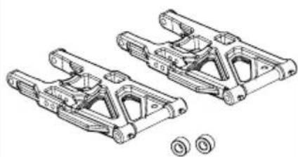
Technical line drawing of three mechanical components with mounting brackets (no text or symbols)500205949 Lower Arms kit front (2)
Querlenker-Set unten vo. (2)
natural_image
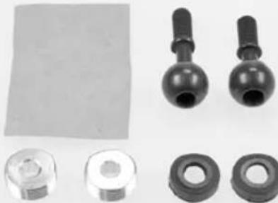
Technical line drawing of two mechanical components with no visible text or symbols500205961 Pivot-Ball Set
Pivot-Ball Set
natural_image
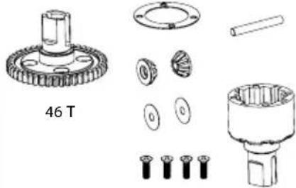
Collection of mechanical components including bolts, washers, and flanges (no text or symbols visible)500405592 Centerdiff complete Mitteldiff komplett
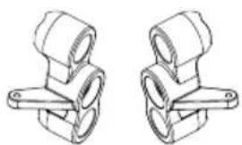
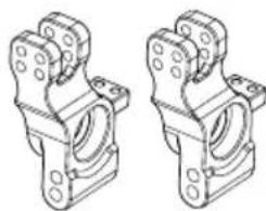
500205950 Rear hub carrier + Axle (2)
Achsschenkel hi. + Achsen (2)
natural_image
Technical line drawing of two mechanical bracket assemblies (no text or symbols)500405588 Steering-link Lenkstange
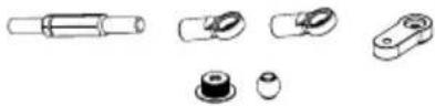
500405619 Hinge pins f. arms
Querlenkerstifte
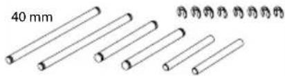
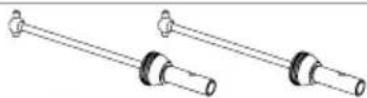
500205957 Axles rear (2)
Achsen hinten (2)
500405589 Schraubenset
Schraubenset
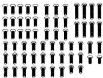
natural_image
Grid of identical black cylindrical objects arranged in rows and columns (no text or symbols)500405620 Alu Steering rack Lenkplatte
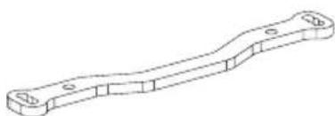
natural_image
Technical line drawing of a mechanical lever or bracket (no text or symbols)ERSATZTEILE • SPARE PARTS
500405765 Chassis Chassis
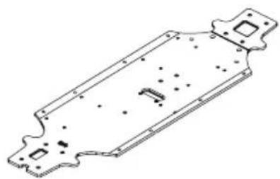
natural_image
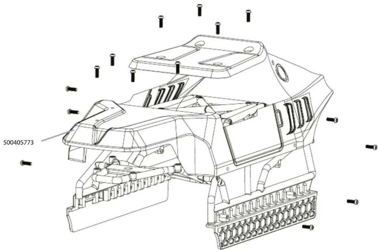
Technical line drawing of a metal plate with mounting holes and internal features (no text or symbols)500405772 Karosseriehalter
Bodyholder Kit
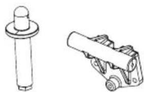
natural_image
Technical line drawing of a mechanical component with a cylindrical shaft and a cylindrical roller (no text or symbols)natural_image
Technical line drawing of two mechanical components with mounting holes and housing (no text or symbols)natural_image
Technical line drawing of two mechanical brackets with mounting holes (no text or symbols)natural_image
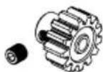
Technical line drawing of a mechanical assembly with two views (top and side), no visible text or symbols409023-02 Motorritzel Piniongear
natural_image
Two identical cylindrical mechanical rods with flanged ends, no text or symbols presentnatural_image
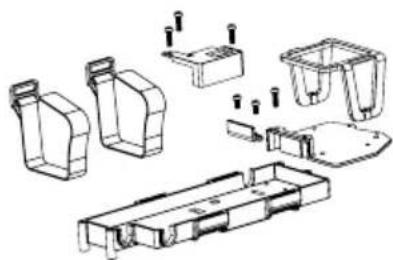
Technical line drawing of a mechanical assembly with no visible text or symbols500405768 Akkuhalter Set Battery holder
natural_image
Technical line drawing of a mechanical assembly with multiple housing components and mounting holes (no text or labels)500900138 Räderset (4)
Wheelset (4)
natural_image
Four identical circular objects with textured, patterned surfaces, resembling mechanical or decorative designs (no text or symbols)NOTIZEN / NOTES


- FR // Remarque importante
- AUFLADEN DES FAHRAKKUS
- ACHTUNG!
- EINLEGEN DER FAHRAKKUS
- STEUERN DES MODELLS
- Limited Warranty
- The Warranty does not cover:
- Declaration of conformity
- CONTENTS
- INCLUDED ITEMS ACCESSORIES
- TECHNICAL DATA
- SAFETY PRECAUTIONS
- Safety Instructions and Intended Use
- This model is not a toy!
- Before use, you must make sure of the following points:
- Pay attention to the charge level indication on your transmitter.
- SAFETY PRECAUTIONS LITHIUM BATTERIES
- General
- Warning notices
- Charging instructions
- Storage instructions
- General terms of guarantee
- Exclusion of liability
- 7.Disposal instructions
- CHASSIS
- REMOVING THE BODY
- CHARGE BATTERY PACK
- Beware:
- ATTENTION!
- INSERTING THE DRIVE BATTERIES
- Advice
- TURN ON THE RC SYSTEM
- CAUTION!
- HOW TO CONTROL YOUR MODEL
- ESC - FEATURES
- ESC - CONNECTION/CABLING
- Connect the ESC, motor, receiver, battery and servo according to the following diagram.
- ESC - BASIC SETTINGS
- Throttle range setting (throttle range calibration)
- Note 1
- Note 2
- Release the SET key as soon as the red LED flashes.
- The neutral point
- The end point of forward direction
- The end point of backward direction
- THROTTLE RANGE EXPLANATION
- LED status of normal running
- Alert tones
- Protection function
- PROGRAM THE ESC
- Programmable items (the italics texts in the form are the default settings)
- Explanation for each programmable item
- Running mode
- Drag brake force in neutral position
- Low voltage cut-off
- Acceleration mode (also called "Punch")
- Maximum Brake Force
- Program the ESC with the "SET" button
- Reset all items to default values
- PROGRAM THE ESC WITH THE SET BUTTON
- The following is a flowchart sample for programming the Dragster S6 controller.
- Note:
- ESC - CONNECTING PROGRAM CARD
- Cher client
- RÄDER • WHEELS
- KAROSSERIE • BODY
- ERSATZTEILE • SPARE PARTS
- NOTIZEN / NOTES
Brand : Carson
Model : Virus Race 4.1
Category : Remote control toy