
Unico Tower Inverter 12 HP - Air Conditioning OLIMPIA SPLENDID - Free user manual and instructions
Find the device manual for free Unico Tower Inverter 12 HP OLIMPIA SPLENDID in PDF.

| Product type | Monobloc air conditioner (wall-mounted) |
| Brand | Olimpia Splendid |
| Model | Unico Tower Inverter 12 HP |
| Dimensions (L x H x D) | 903 x 520 x 215 mm |
| Power supply | 220-240 V ~ 50 Hz |
| Refrigerant gas | R-410A |
| Operating modes | Cooling, Heating (heat pump), Dehumidification, Fan, Auto (Comfort) |
| Special functions | ECO, SILENT, Programmable timer (2 programs), Deflector oscillation |
| Remote control | Infrared with display, AAA batteries (2 x 1.5 V) |
| Air filter | Washable, cleaning recommended every 2 weeks or when indicator lights up |
| Installation | Requires 2 holes of 162 mm diameter in the wall, supplied with template and external grilles |
| Electrical protection | Omnipolar disconnection device, recommended 10 A fuse, mandatory grounding |
| Safety | Automatic shutdown in case of anomaly, compressor protection (3 min delay), alarms on display |
| Periodic maintenance | Filter cleaning every 2 weeks, cleaning of coil and condensate tray by technician |
| Spare parts | Filters, remote control, batteries, external grilles, flange, condensate tube |
| Temperature limits (cooling) | Indoor: 18-35°C DB; Outdoor: -10 to 43°C DB |
| Temperature limits (heating) | Indoor: 16-27°C DB; Outdoor: -15 to 24°C DB |
| Weight | Not specified |
Frequently Asked Questions - Unico Tower Inverter 12 HP OLIMPIA SPLENDID
User questions about Unico Tower Inverter 12 HP OLIMPIA SPLENDID
0 question about this device. Answer the ones you know or ask your own.
Ask a new question about this device
Download the instructions for your Air Conditioning in PDF format for free! Find your manual Unico Tower Inverter 12 HP - OLIMPIA SPLENDID and take your electronic device back in hand. On this page are published all the documents necessary for the use of your device. Unico Tower Inverter 12 HP by OLIMPIA SPLENDID.
USER MANUAL Unico Tower Inverter 12 HP OLIMPIA SPLENDID
natural_image
Line drawing of a rectangular industrial or storage unit with a top panel and side-mounted control panel (no text or symbols)m = 311
- L'appareil contient du gaz R-410A. L'R-410A est un gaz à effet de serre fluoré.
- Respecter les lois en vigueur.
- Attention : le réfrigérant R-410A est inodore
- L'appareil peut être utilisé par des enfants d'au moins 8 ans et par des personnes ayant des capacités physiques, sensorielles ou mentales réduites, ou dépourvues de l'expérience ou des connaissances nécessaires, à condition que ce soit sous surveillance ou qu'elles aient reçu des instructions relatives à l'utilisation sûre de l'appareil et à la compréhension des dangers qui y ont liés.
- Les enfants ne doivent pas jouer avec l'appareil.
- Le nettoyage et la maintenance destinés à être effectués par l'utilisateur ne doivent pas être effectués par des enfants sans surveillance.
- Si le cordon d'alimentation est abîmé, il doit être remplacé par le fabricant ou par son service d'assistance technique ou, dans tous les cas, par une personne ayant une qualification similaire, de façon à prévenir tout risque.
- L'installation, la mise en service et les phases de maintenance ultérieures, à l'exception du nettoyage du filtre à air, doivent être effectuées exclusivement par du personnel autorisé et qualifié.
- Pour prévenir tout risque d'électrocution, il est indispensable de débrancher la fiche de la prise de courant et/ou détacher l'interrupteur général avant d'effectuer de branchements électriques et chaque opération d'entretien sur les appareils.
-
Pendant l'installation, respecter les références des espaces minimums indiqués sur la figure 2.
-
Das Gerät enthält das Gas R-410A. R-410A ist ein fluoriertes Treibhausgas.
- Die geltenden Gesetze befolgen.
- Beachten Sie, dass das Kühlmittel R-410A geruchslos ist
- Kindern ab 8 Jahren sowie Personen mit körperlichen, sensoriellen oder mentalen Beeinträchtigungen beziehungsweise Personen ohne entsprechende Erfahrung oder Kenntnisse darf die Benutzung des Geräts erlaubt werden unter der Bedingung, dass die Kinder sowie die genannten Personen beaufsichtigt beziehungsweise in die für die Verwendung des Geräts geltenden Sicherheitsvorkehrungen eingewiesenen wurden und die mit dem Gerät verbundenen Gefahren verstanden haben.
- Kinder dürfen nicht mit dem Gerät spielen.
- Die dem Benutzer obliegenden Reinigungs- und Pflegearbeiten dürfen nicht von unbeaufsichtigten Kindern durchgeführt werden.
- Wenn das Stromkabel beschädigt ist, muss dieses zur Vermeidung jeglicher Gefahren vom Hersteller oder von dessen Technischem Kundendienst beziehungsweise durch gleichermaßen qualifiziertes Personal ersetzt werden, um jeglicher Gefahr vorzubeugen.
- Installation, erste Inbetriebnahme und die anschließenden Wartungsphasen, ausgenommen Reinigung oder Waschen, sind ausschließlich durch befugtes Fachpersonal auszuführen.
- Um jegliches Risiko eines Stromschlags vorzubeugen, ist es unerlässlich, das Netzkabel aus der Steckdose zu ziehen bzw. Den Hauptschalter auszuschalten, bevor elektrische Verbindungen oder jegliche andere Wartungsarbeit an den Geräten vorgenommen werden.
-
Bei der Installation die in Abbildung 2 aufgezeigten Mindestabstände einhalten.
-
El aparato contiene gas R-410A. R-410A es un gas de efecto invernadero fluorado.
- Respete las leyes vigentes.
- Atención: se recuerda que el refrigerante R-410A es inodoro
- El aparato puede ser utilizado por niños mayores de 8 años y por personas con capacidades físicas, sensoriales o mentales reducidas, o carentes de la experiencia y conocimiento necesarios, siempre que lo hagan bajo vigilancia o después de haber recibido instrucciones sobre el uso seguro del aparato y sobre los peligros inherentes al mismo.
- Los niños no deben jugar con el aparato.
- Las operaciones de limpieza y mantenimiento a cargo del usuario no deben ser realizadas por niños sin vigilancia.
- En caso de deterioro del cable de alimentación, debe ser sustituido por el fabricante, por el servicio de asistencia técnica o por una persona con cualificación similar, para prevenir cualquier riesgo.
- La instalación, la primera puesta en marcha y las posteriores operaciones de mantenimiento, excepto la limpieza o el lavado del filtro de aire ambiente, deben ser realizadas exclusivamente por personal autorizado y cualificado.
- Para prevenir cualquier riesgo de electrocución, es imprescindible desconectar el enchufe de la toma de corriente y/o apagar el interruptor general antes de efectuar conexiones eléctricas y cada operación de mantenimiento en los aparatos.
- Durante la instalación, respete las referencias a los espacios mínimos indicados en la figura 2.
natural_image
Architectural cross-section diagram of a building facade with brick wall and ventilation duct (no text or symbols)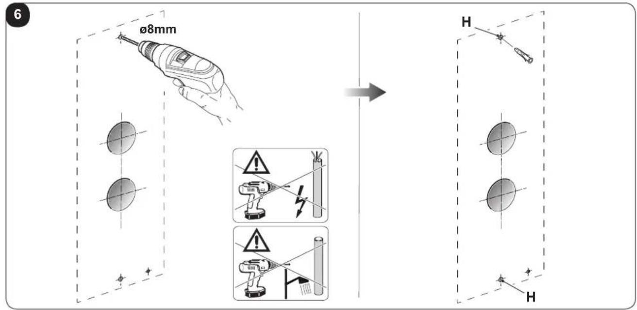
natural_image
Illustration of a hand using a tool to trim a chain, no text or symbols present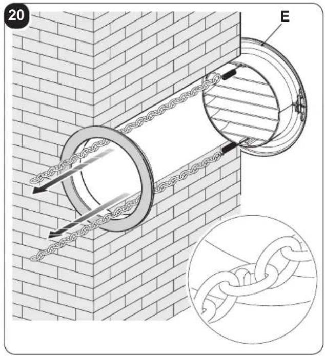
23
natural_image
3D diagram of a rectangular enclosure with mounting feet and a label pointing to the top panel (no text or symbols on the main structure)O
25
natural_image
Technical line drawing of a mechanical device with internal components and labeled parts (no readable text or symbols)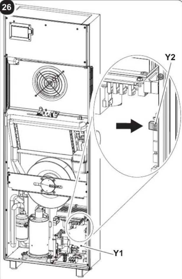
natural_image
Diagram of a cylindrical device with internal components and an external housing, showing no text or symbols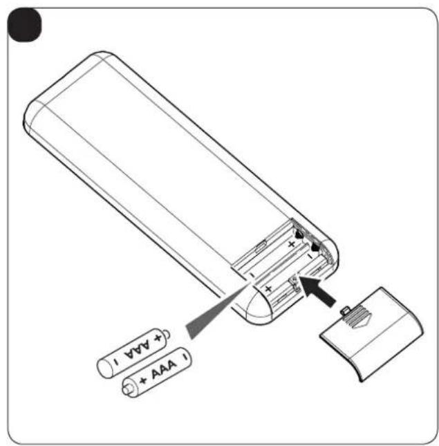
natural_image
Technical line drawing showing two industrial equipment units with a close-up of a grid-patterned panel mounted on a vertical wall (no text or symbols)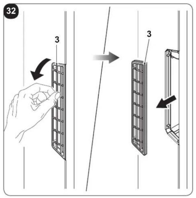
natural_image
Illustration of two different hand welding or cleaning techniques on a shared base panel, showing hand positioning and tool path (no text or symbols)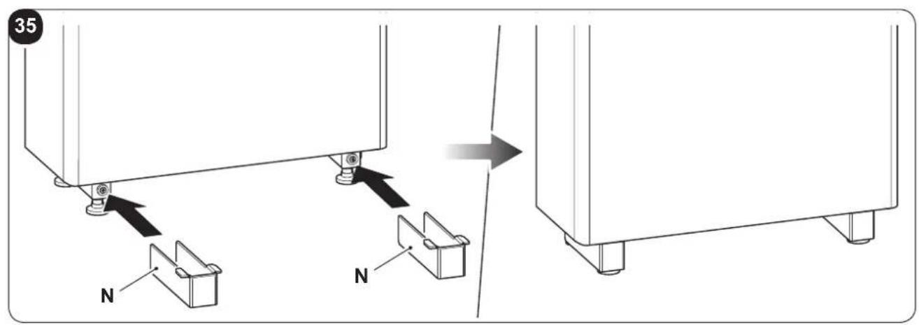
INDICE GENERALE
0 - AVVERTENZE....3
0.1 - INFORMAZIONI GENERALI 3
0.2 - SIMBOLOGIA....3
0.2.1 - Pittogrammi redazionali....3
0.3 - AVVERTENZE GENERALI 5
0.4 - NOTE SUI GAS FLUORURATI 8
0.5 - USO PREVISTO 8
0.6 - ZONE DI RISCHIO....8
1 -DESCRIZIONE APPARECCHIO 9
1.1 - ELENCO COMPONENTI FORNITI A CORREDO 9
1.2 - IMMAGAZZINAMENTO 9
1.3 - RICEVIMENTO E DISIMBALLO 9
1.4 - DESCRIZIONE COMPONENTI APPARECCHIO....10
INFORMAZIONI RISERVATE AL "TECNICO INSTALLATORE"
2 - INSTALLAZIONE
natural_image
Illustration of a hand using a power plug to install an electrical socket (no text or symbols present)
2.6 - ACCESSORI B1014, B1012, B1015
natural_image
Illustration of a hand inserting a plug into an electrical outlet (no text or symbols)
natural_image
Illustration of a hand inserting a plug into an electrical outlet (no text or symbols)1 -DESCRIPTION OF THE APPLIANCE 9
1.1 - LIST OF THE COMPONENTS SUPPLIED 9
1.2 - STORAGE....9
1.3 - RECEIPT AND UNPACKING 9
1.4 - APPLIANCE COMPONENTS DESCRIPTION....10
INFORMATION RESERVED FOR THE "INSTALLATION TECHNICIAN"
2 - INSTALLATION 10
2.1 - INSTRUCTIONS FOR INSTALLATION....10
2.2 - SIZE AND SPECIFICATIONS OF THE ROOM IN WHICH TO INSTALL THE AIR CONDITIONER......11
2.3 - CHOOSING THE POSITION OF THE UNIT 11
2.4 - UNIT ASSEMBLY 12
2.4.1 - Drilling the wall 12
2.4.2 - Preparing the condensate discharge....13
2.4.3 - Assembly of the air ducts and external grids....14
2.4.4 - Positioning the appliance on the anchorage bracket (anti-tip over device)....14
2.4.5 - Electric hook-up....15
2.5 - ENERGY BOOST/SYSTEM ENABLE CONTACT INPUT 16
2.6 - ACCESSORIES B1014, B1012, B1015 16
SECTION FOR THE TECHNICIAN AND USER
3 -USE 17
3.1 - WARNINGS....17
3.2 - DESCRIPTION OF THE WARNING PANEL 17
3.3 - CONTROL PANEL NOTIFICATIONS....18
3.4 - USE OF THE REMOTE CONTROL....19
3.4.1 - Insertion of batteries....20
3.4.2 - Replacement of batteries 20
3.4.3 - Location of the remote controller....20
3.5 - DESCRIPTION OF REMOTE CONTROL....21
3.5.1 - Description of the remote control keys....21
3.5.2 - Description of the remote control display 21
3.6 - DESCRIPTION OF THE AIR CONDITIONER FUNCTIONS....22
3.6.1 - Main switch-on and running management .....22
3.6.2 - ECO key 22
3.6.3 - Turning the unit ON/OFF 22
3.6.4 - Operation in "Cooling" mode only....22
3.6.5 - Operation in "Dehumidification" mode only 22
3.6.6 - Operation in "Ventilation" mode only 23
3.6.7 - Operation in "Spa" mode only (Automatic)....23
3.6.8 - Operation in "Heating" mode only 23
3.6.9 - Checking airflow direction 24
EN - 1
3.6.10 - Checking fan speed 24
3.6.11 - SILENT key 24
3.6.12 - Timer setting....24
3.6.13 - Timer and clock setting 25
3.6.14 - Timer setting....25
3.6.15 - Timer activation and deactivation....26
3.6.16 - Reset of all the remote control functions....26
3.6.17 - Managing the unit if the remote control is not available 26
3.7 - RECOMMENDATIONS FOR ENERGY SAVINGS....26
4 - MAINTENANCE AND CLEANING 27
4.1 - CLEANING....27
4.1.1 - Appliance and remote control cleaning 27
4.1.2 - Cleaning the air filters....27
4.2 - MAINTENANCE 28
4.2.1 - Routine maintenance 28
4.3 - DIAGNOSIS, ALARMS AND INCONVENIENCES....29
4.3.1 - Diagnosis of the inconveniences....29
4.3.2 - Functional aspects not to be mistaken for anomalies .....29
4.3.3 - Console alarms .... 30
4.3.4 - Anomalies and remedies....31
5 - TECHNICAL DATA....32
This symbol on the product or its packaging indicates that the appliance cannot be treated as normal domestic trash, but must be handed in at a collection point for recycling electric and electronic appliances.
Your contribution to the correct disposal of this product protects the environment and the health of your fellow men. Health and the environment are endangered by incorrect disposal.
Further information about the recycling of this product can be obtained from your local town hall, your refuse collection service, or in the store at which you bought the product.
This regulation is valid only in EU member states.
EN - 2
ILLUSTRATIONS
The illustrations are grouped on the initial pages of the manual
MAIN INDEX
The main index of this manual is given on page "EN-1"

0 - WARNINGS
0.1 - GENERAL INFORMATION
First of all, we would like to thank you for choosing our appliance.
This document is confidential pursuant to the law and may not be reproduced or transferred to third parties without the explicit authorisation of the manufacturer. The appliance may undergo updates and therefore have details different from those represented, without prejudice to the texts contained in this manual.
0.2 - SYMBOLS
The pictograms in the next chapter provide the necessary information for correct, safe use of the machine in a rapid, unmistakable way.
0.2.1 - Editorial pictograms

Service
Refers to situations in which you should inform the SERVICE department in the company: CUSTOMER TECHNICAL SERVICE.

Index
Paragraphs marked with this symbol contain very important information and recommendations, particularly as regards safety.
Failure to comply with them may result in:
- danger of injury to the operators
- loss of the warranty
- refusal of liability by the manufacturer.

Raised hand
Refers to actions that absolutely must not be performed.
als to the personnel that the operation described could cause electrocution if not performed according to the safety rules.

GENERIC DANGER
It informs the personnel concerned that if the operation is not carried out in compliance with the safety regulations, it presents the risk of suffering physical damage.

DANGER DUE TO HEAT
It informs the personnel concerned that if the operation is not carried out in compliance with the safety regulations, it presents the risk of burns due to contact with components at very high temperatures.

DO NOT COVER
ates to the personnel concerned, that it is prohibited to cover the appliance, to prevent over-heating.

ATTENTION
Indicates that this document must be read carefully before installing and/or using the appliance.
- Indicates that the assistance personnel must handle the appliance following the installation manual.

ATTENTION
Indicates that there may be additional information in attached manuals. Indicates that information is available in the user manual or in the installation manual.

ATTENTION
rates that the assistance personnel must handle the appliance following the installation manual.

EN - 4
0.3 - GENERAL WARNINGS
WHEN USING ELECTRICAL EQUIPMENT, BASIC SAFETY PRECAUTIONS MUST ALWAYS BE FOLLOWED IN ORDER TO REDUCE RISKS OF FIRE, ELECTRIC SHOCKS AND INJURY, INCLUDING THE FOLLOWING:
- This document is restricted in use to the terms of the law and may not be copied or transferred to third parties without the express authorization of the manufacturer, OLIMPIA SPLENDID.
Our machines are subject to change and some parts may appear different from the ones shown here, without this affecting the text of the manual in any way.
-
Read this manual carefully before performing any operation (installation, maintenance, use) and follow the instructions contained in each chapter.
-
Make all personnel involved in transport and installation of the machine aware of these instructions.
-
THE MANUFACTURER IS NOT RESPONSIBLE FOR DAMAGES TO PERSONS OR PROPERTY CAUSED BY FAILURE TO FOLLOW THE INSTRUCTIONS IN THIS MANUAL.
-
The manufacturer reserves the right to make any changes it deems advisable to its models, although the essential features described in this manual remain the same.
-
The installation and maintenance of air-conditioners like this one may be hazardous as they contain a cooling gas under pressure as well as powered parts.
Therefore, the installation, first startup and subsequent maintenance should be carried out exclusively by authorized, qualified personnel.
-
Failing to comply with the instructions contained in this manual, and using the unit with temperatures exceeding the permissible temperature range will invalidate the warranty.
-
Routine maintenance of the filters and general external cleaning can be done by the user as these operations are not difficult or dangerous.
-
During installation and maintenance, respect the precautions indicated in the manual, and on the labels applied inside the units, as well as all the precautions suggested by good sense and by the safety regulations in effect in your country.
-
Always wear gloves and protective goggles when performing any operations on the refrigerating side of the units.

- Air conditioners must not be installed in places containing inflammable gasses, explosive gasses, or in very humid environments (laundries, greenhouses, etc.), or in places where there are machines that generate very great heat.

- In case of replacement of parts, use only original OLIMPIA SPLENDID parts.

- IMPORTANT! prevent all risk of electrocution, it is essential to disconnect the plug from the power outlet before making the electric connections and performing any cleaning and/or maintenance operations on the appliances.

- Lightening, cars in the vicinity and mobile phones can cause malfunctioning. Disconnect the unit electrically for a few seconds and then re-start the air conditioner.

- On rainy days, it is recommended to connect the electric power supply in order to prevent damage caused by lightening.

- If the unit is unused for a long period, or no-one uses the climate-controlled room, it is recommended to disconnect the electric power supply in order to prevent accidents.

- Do not use liquid or corrosive detergents to clean the unit, do not spray water or other liquids onto the unit, since they could damage the plastic components or even cause electric shocks.

- Do not wet the indoor unit and the remote control. Short circuits or fires may occur.

- In the event of operating anomalies (e.g. strange noise, bad odour, smoke, abnormal temperature rise, electric dispersions, etc.) disconnect the electric power supply immediately.
Contact the local dealer.
- Do not let the air conditioner run for a long time when the humidity is very high and a door or a windows is left open.
Moisture may condense and wet or damage furniture.

- Do not plug or unplug the power supply plug during operation and electric shocks risk.

- Do not touch (operation) the product with wet hands and electric shocks risk.

- Do not place a heater or other appliance near the power cable. Fire and electric shocks risk.
EN - 6

- Make sure water does not enter the electrical parts. could cause fires, product failure or electric shocks.

- Do not open the air inlet grid during appliance operation. Risk of injury, electric shock or damage to the product.

- Do not block the air inlet or outlet; the product could be damaged.

- Do not insert hands or other object through air inlet or outlet while the product is operated.
The presence of sharp and moving parts could cause injury.
- Do not drink the water drained from the product. It is not sanitary could cause serious health issues.

-
When there are gas leaks from other units, ventilate the room well before activating the air conditioner.
-
Do not disassemble or modify unit.
-
Ventilate the room well when used together with a stove, etc.
-
Do not use for special purposes.
-
The persons that work or intervene on a cooling circuit, must be in possession of suitable certification, issued by an accredited assessment body. This must attest skill in safely handling refrigerants in compliance with assessment specification acknowledged by sector associations.
-
Do not emit R-410A gas into the atmosphere; R-410A is a fluorinated greenhouse gas with a Global Warming Potential (GWP) = 2088.

- The appliance described in this manual is in compliance with the following European Regulations
• ECODESIGN 2009/125/EC, 206/2012/EU
• ENERGY LABELLING 2012/30/EU, 626/2011/EU
and successive amendments.
0.4 - NOTES REGARDING FLUORINATED GASES

- This climate control appliance contains fluorinated gas. For specific information regarding the type and quantity of gas, refer to the data plate affixed to the unit.
- The installation, assistance, maintenance and repair of the appliance, must be performed by a qualified certified technician.
- Product removal and re-cycling operations must be performed by a qualified certified technician.
- If the system has a leak-detection device installed, the checks for leaks must be performed at least every 12 months.
- When the unit is checked for leaks, keeping a record of all inspections is highly recommended.
0.5 - PROPER USE
- The air-conditioner should be used for the exclusive purpose of producing hot or cool air (on demand) for the sole purpose of obtaining a comfortable temperature in the room.
- An improper use of the devices (external and internal) with possible damages caused to people, things or animals relieves OLIMPIA SPLENDID from any liability.
0.6 - HAZARDOUS ZONES
- The climate controllers must not be installed in environments with the presence of inflammable gases, explosive gases, in very humid environments (laundries, greenhouses, etc.), or in places with other machines that generate a strong heat source, in proximity of a sources of salt water or sulphurous water.

- DO NOT use gas, gasoline or other inflammable liquids near to the climate controller.
- The climate controller does not have a fan for the introduction of fresh outdoor air into the room; ventilate by opening doors and windows.

• Always install circuit breaker and a dedicated power circuit.
This product must be used exclusively according to the specifications indicated in this manual. Use different to that specified, could cause serious injuries.
THE MANUFACTURER IS NOT LIABLE FOR INJURY/DAMAGE TO PERSONS/OBJECTS DERIVING FROM FAILURE TO COMPLY WITH THE REGULATIONS CONTAINED IN THIS MANUAL.
EN - 8
1 - DESCRIPTION OF THE APPLIANCE
1.1 - LIST OF THE COMPONENTS SUPPLIED
The units making up the climate control system are packaged individually in cardboard boxes.
Individual unit packages can be transported by hand by two members of personnel, or loaded onto a transport trolley; up to max. three packages stacked for indoor units and individually for outdoor units.
Before beginning to assemble the unit, make sure all the parts are within easy reach.

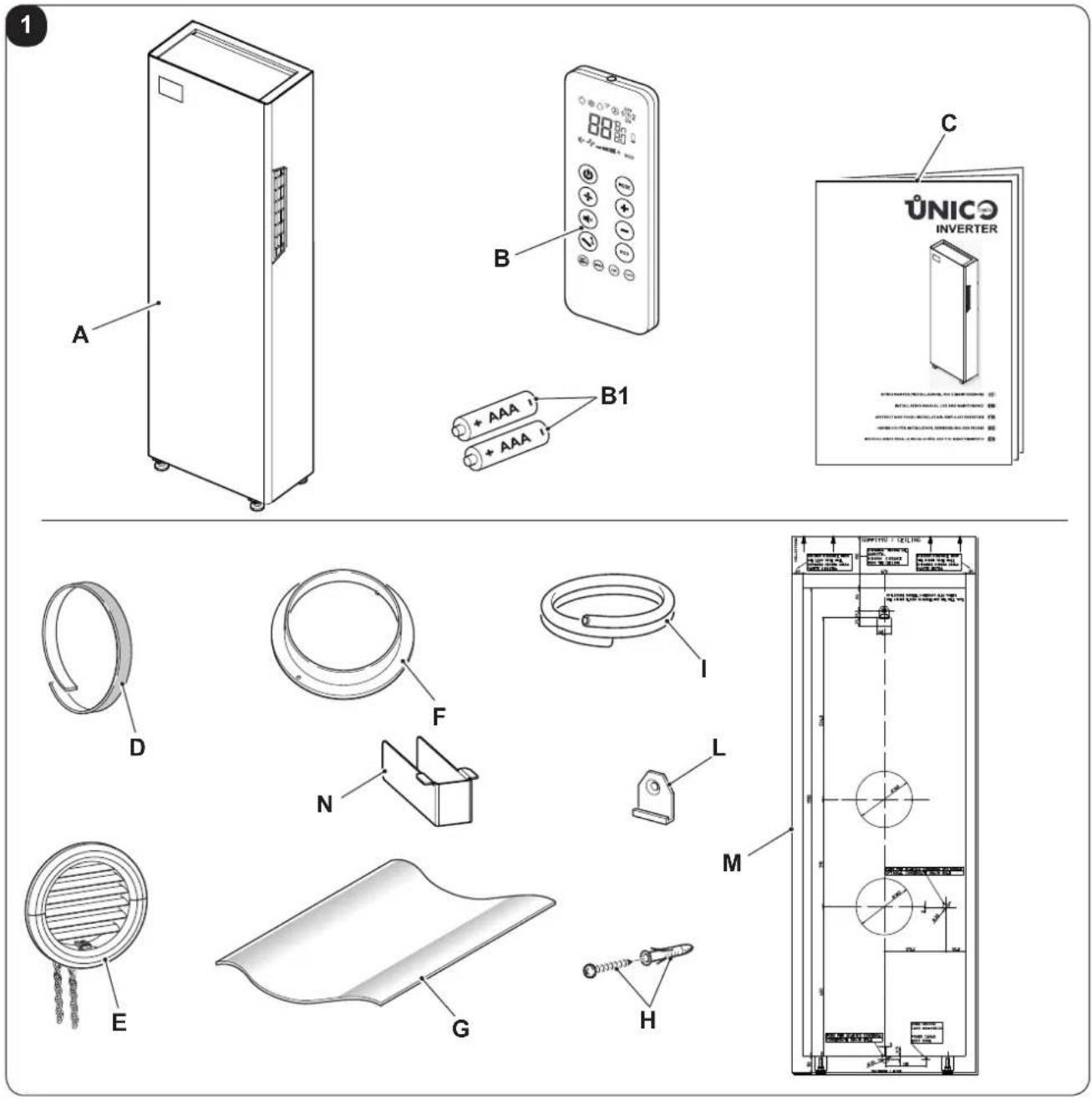
The parts listed below and shown in figure 1 are included in the supply, the other particulars necessary for installation must be purchased.
A. Appliance UNICO TOWER
B. Remote control
B1. Battery for remote control quantity 2 - AAA type x 1.5V
C. Use and maintenance booklets + warranty
D. Strip of adhesive isolating tape (x 2)
E. Air inlet and outlet external grids including chains and kit for installing the grids (x 2)
F. Internal flanges (x 2)
G. Sheet for wall pipes (x 2)
H. Kit of screws and anchor bolts
I. Condensation drain pipe
L. Wall anchoring bracket
M. Paper template to make holes
N. Adjustable feet aesthetic cover (x 2)
1.2 - STORAGE
Store the cartons in a closed environment protected against atmospheric agents and raised off the floor by planks or a pallet.

DO NOT TURN THE PACKAGING UPSIDE DOWN NOR PLACE IT HORIZONTALLY.
1.3 - RECEIPT AND UNPACKING
The packaging is made up from suitable material and performed by expert personnel.
The units are delivered complete and in perfect condition. However, for he quality control of the transport services, follow the warnings below:
a. On receipt of the packages, check whether the packaging is damaged. If this is the case, withdraw the goods with reserve, producing photographic proof and any apparent damage.
b. Unpack, checking the presence of the individual components with the packing lists.
c. Control that all components have not undergone damage during transport. If this is the case, inform the carrier by registered letter with acknowledgement of receipt within 3 days of receiving the goods, presenting photographic documentation.
d. Pay attention when unpacking and installing the equipment.
Sharp parts can cause injury. Pay particular attention to the edges of the structure and the fins of the condenser and evaporator.

No information concerning damage undergone can be taken into consideration after 3 days from delivery.
For any controversy the court of jurisdiction will be BRESCIA.
EN - 9

Keep the packaging for at least the duration of the warranty period, for any shipments to the after-sales centre for repairs. Dispose of packaging in compliance with the regulations in force regarding waste disposal.
1.4 - APPLIANCE COMPONENTS DESCRIPTION
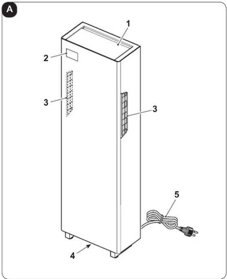
The main components of the air conditioner are shown in figure A.
- Air outlet deflector (Flap)
- Function and alarms display console
- Air intake grids and air filters
- Condensation discharge
- Power cord
2 - INSTALLATION
2.1 - INSTRUCTIONS FOR INSTALLATION
To obtain the best results and optimum performance, follow the instructions for correct installation provided in this manual.

A failure to implement the indicated standards, which may cause a malfunction of the appliances, relieves OLIMPIA SPLENDID from any form of warranty and from any liability for possible damages caused to people, animals or things.

The electrical system must be compliant with legal standards, must respect the data in the technical data sheet and be must be equipped with an efficient ground system.
EN - 10

OLIMPIA SPLENDID
2.2 - Size and specifications of the room in which to install the air conditioner
- Before installing the air conditioner, it is essential to make an accurate calculation of the heat load in summer (and cold load in winter for models with heating pump) at the site of installation.
- The more accurate this calculation is made the better the air conditioner will be able to do its job.
- When executing the calculations, refer directly to the prevailing standards.
• For particularly important applications, we recommend contacting expert heating engineers. - The user should try to limit high heat loads as much as possible as follows: glass doors and windows exposed to many hours of sunlight should be fitted on the inside with curtains or, even better, on the outside with coverings such as Venetian blinds, verandahs, refractive film, etc.). The air-conditioned room must remain closed as long as possible.
- Halogen spotlights or other electrical equipment with high power consumption should not be used in the room (toasters, steam irons, hot plates for cooking, etc.).
2.3 - CHOOSING THE POSITION OF THE UNIT
To obtain the best operating performance and prevent faults or hazardous conditions, the position of indoor unit installation must meet the following requirements:
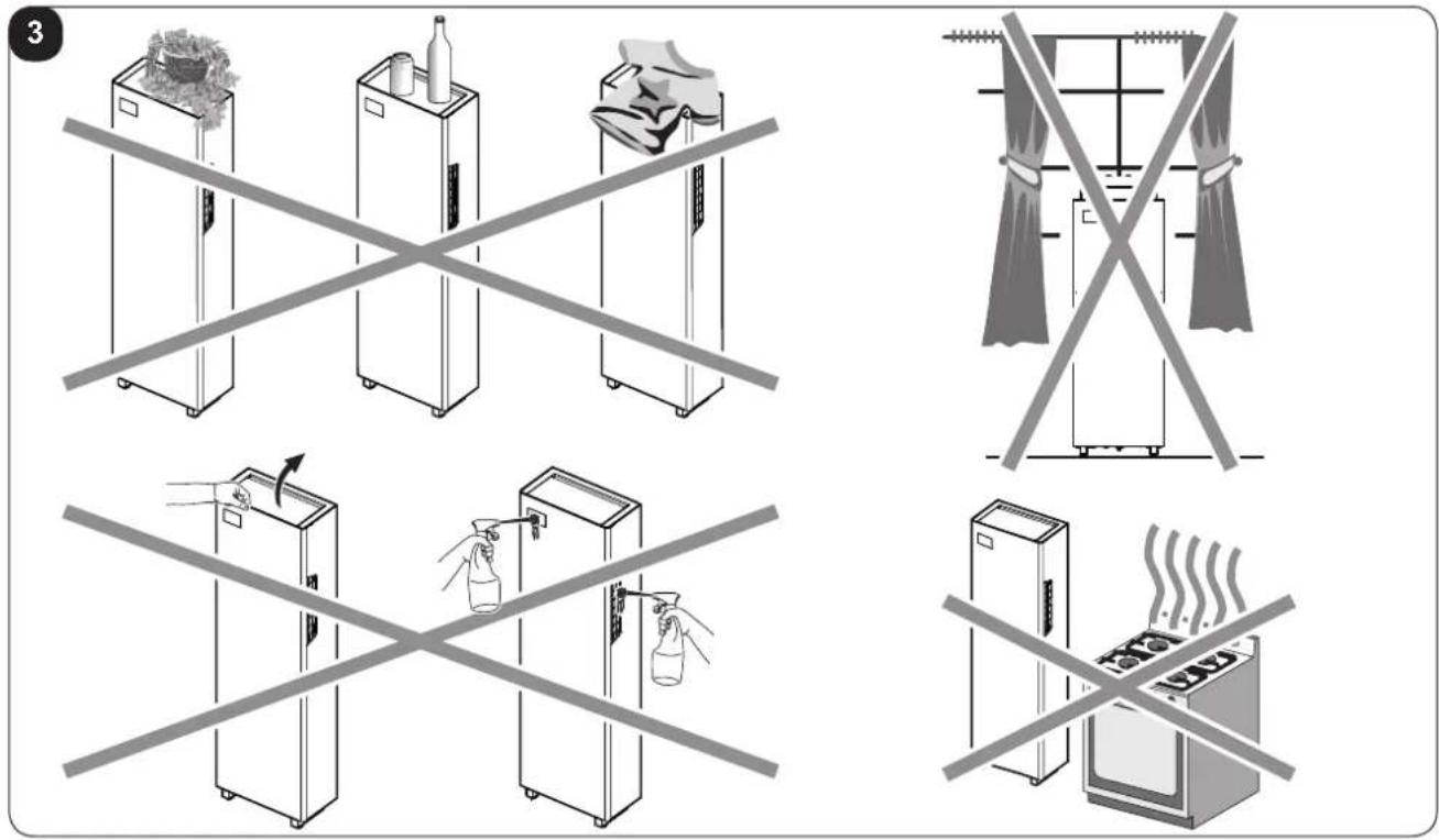
a. Do not expose the appliance to heat or steam sources (fig. 3).
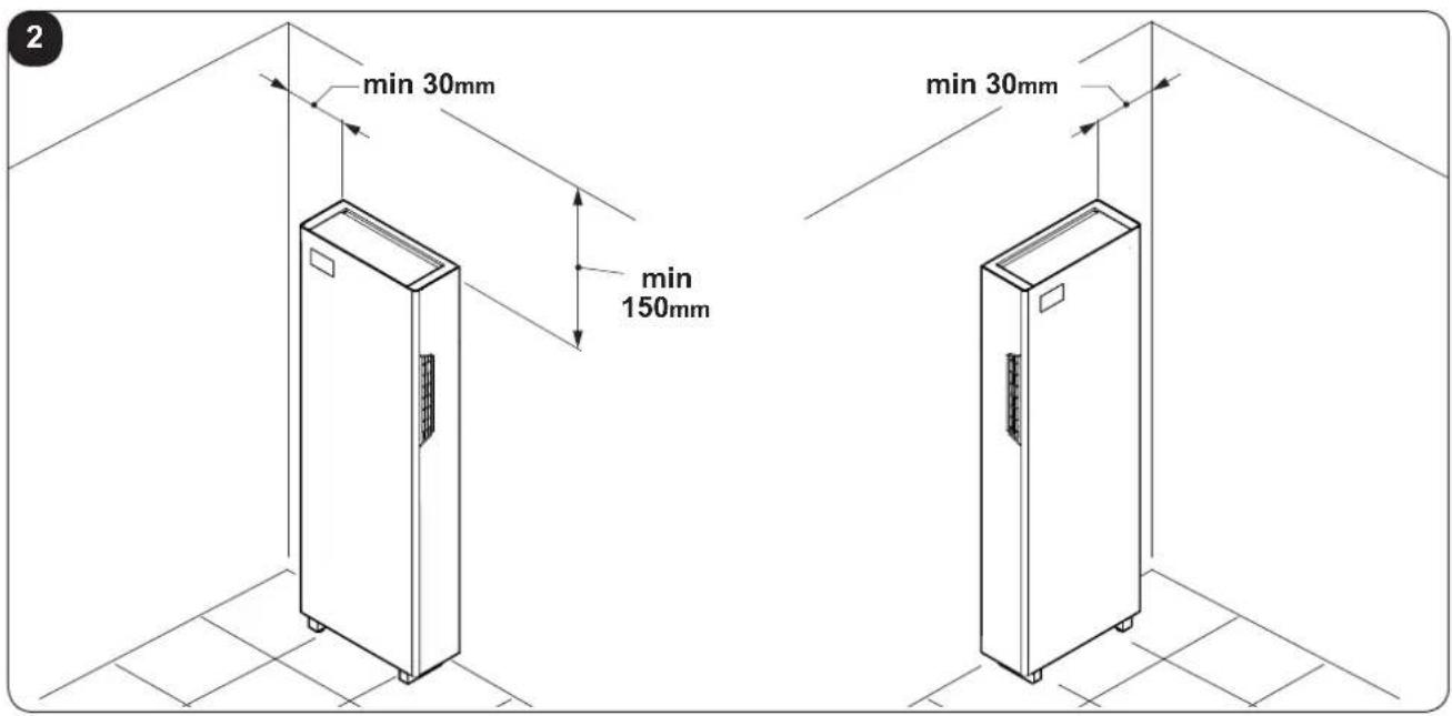
b. Make sure that the space to the right and left is at least 30 mm (fig. 2).
c. The wall where the indoor unit is to be fixed, must be stable, strong and suitable to support the weight.
d. It must be possible to leave room around the unit for any maintenance operations that may be necessary.
e. There must be no obstructions to the free circulation of the air both on the right and left intake sides (curtains, plants, furniture) and to the upper air outlet; this could cause air swirls, which would inhibit correct operation of the appliance (fig. 3).
f. Do not spray water or other liquids of any kind directly on the unit (fig. 3).
g. The appliance must not be positioned so that the air flow is directed directly towards nearby people (fig. 3).
h. Never force the opening of the airflow flap (fig. 3).
i. Do not place bottles, cans, items of clothing, flowers or any other object on the unit (fig. 3).
I. Do not install the air conditioner near to household appliances (TV, radio, fridge, etc.), or on a heat source (fig. 3).

The air conditioner must be installed on a wall that communicates with the outside

After determining the best place for installation as described above, check for the absence of other structures or systems (beams, piers, pipes, wires, etc.) at the points where the holes are to be drilled, which would prevent drilling the holes required to install the unit.
Check again to make sure there are no obstacles to air circulation through the holes to be drilled due to plants and their leaves, slats or panelling, blinds, gratings or grids too dense, etc.).
EN - 11
2.4 - UNIT ASSEMBLY

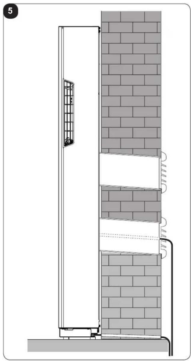
The maximum allowed length of the pipes is 1 m, the pipes must be internally smooth, with a diameter equal to 162 mm and bends cannot be performed.
It is necessary to use the grilles provided, or grilles which keep the same features.
2.4.1 - Drilling the wall
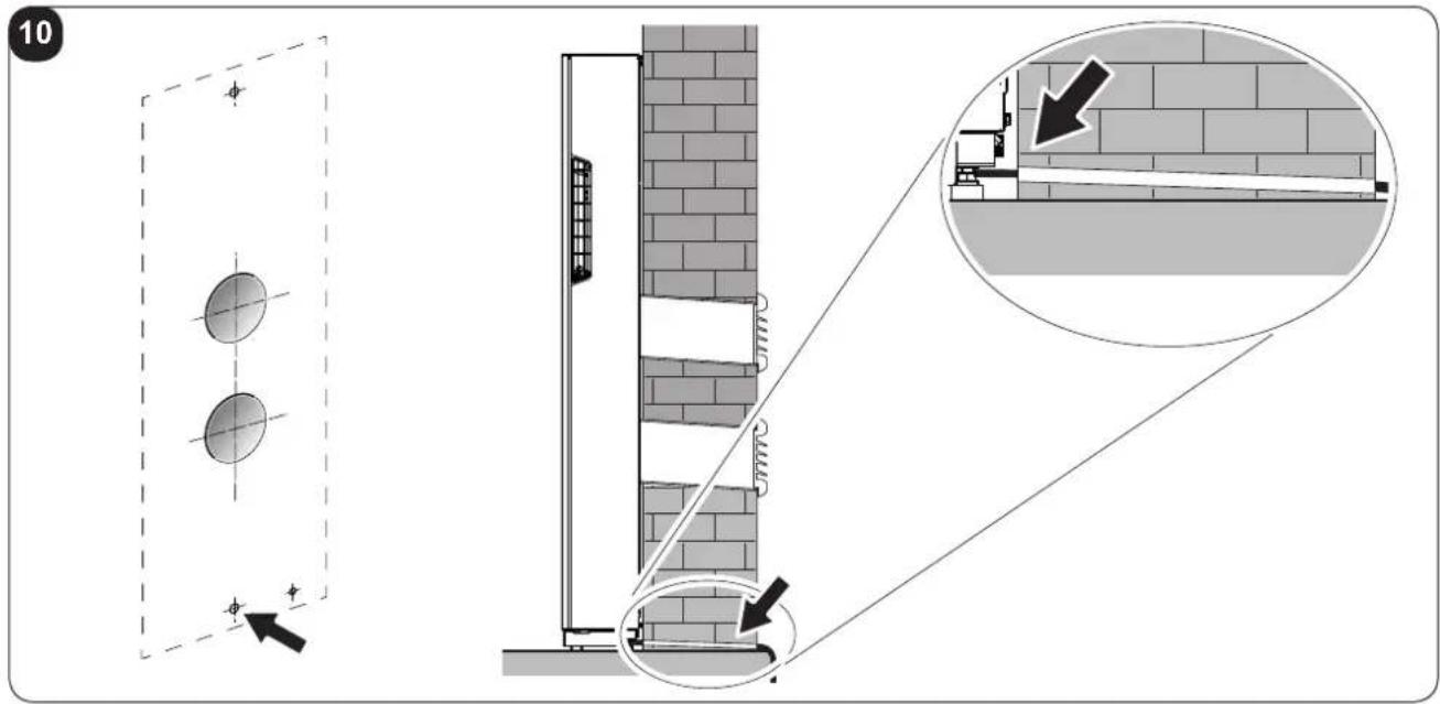
Install the unit by drilling two holes (diameter of either 162 mm) in the wall as indicated in the drilling template.
- Drill the wall using the proper tools to facilitate your job and prevent excess damage or disturbance to your client.
The best tools for drilling large holes in walls are special drills called core borers with very high twisting torque and adjustable rotating speed depending on the diameter of the hole to be drilled.
- To prevent the creation of large amounts of dust and rubble due to drilling, the core borer can be fitted with a vacuum system applied by means of suction cups to the drilling zone.
- Define where to connect the condensate drain pipe to be used (see paragraph 2.4.2):
- In the fitting under the unit base
- In the fitting inside the unit
• To drill the holes, proceed as follows:
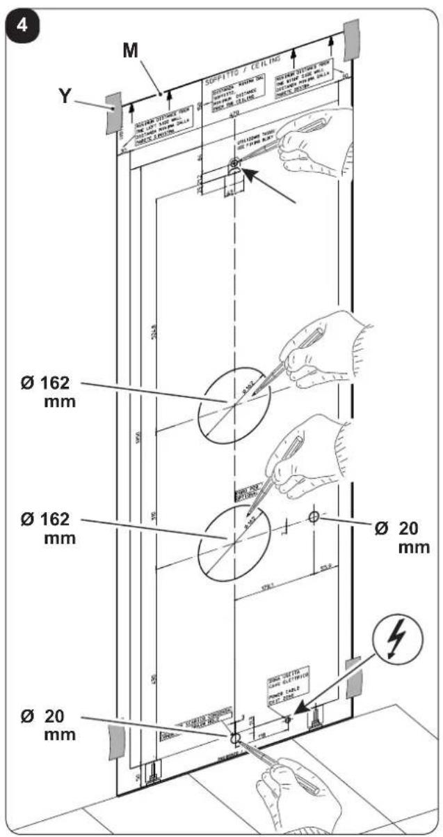
- Place the supplied drill jig (M) against the wall observing the minimum distances from the ceiling, the floor and from the side walls indicated on the jig itself which can be kept in the correct position using adhesive tape (Y) (fig. 4).
- Use a small drill or punch to mark, with extreme care, the exact centre of each of the holes to be drilled (fig.4).
- Using a core boring head measuring at least 162 mm to drill the two holes for entry and exit of the air.

Drill the foregoing holes tilted slightly downwards to prevent water from being fed back through the ducts (fig. 5).

Most of the removed material is expelled outwards, therefore make sure that it does not hit any person or object when it falls out.
In order to avoid as much as possible outer plaster breaking, it is necessary to proceed carefully with the last part of hole execution, decreasing pressure on core borers.
- Drill the holes, previously marked, for the wall plugs related to the fixing brackets (fig. 6).

Carefully check the characteristics and consistency of the wall in order to possibly choose wall plugs specific for particular situations.

The manufacturer will not be held liable for any underestimates made in the structural consistency of the anchor prepared by the installer.
Therefore, pay utmost attention to the foregoing operation that could cause serious injury/damage to people/property if carried out incorrectly.
EN - 12

OLIMPIA SPLENDID
- When installing models equipped with heating pump, if no condensate discharge was built into the wall (see paragraph 2.4.2), in order to drain the condensate it will be necessary to drill a hole through the wall in the position shown on the template.
2.4.2 - Preparing the condensate discharge
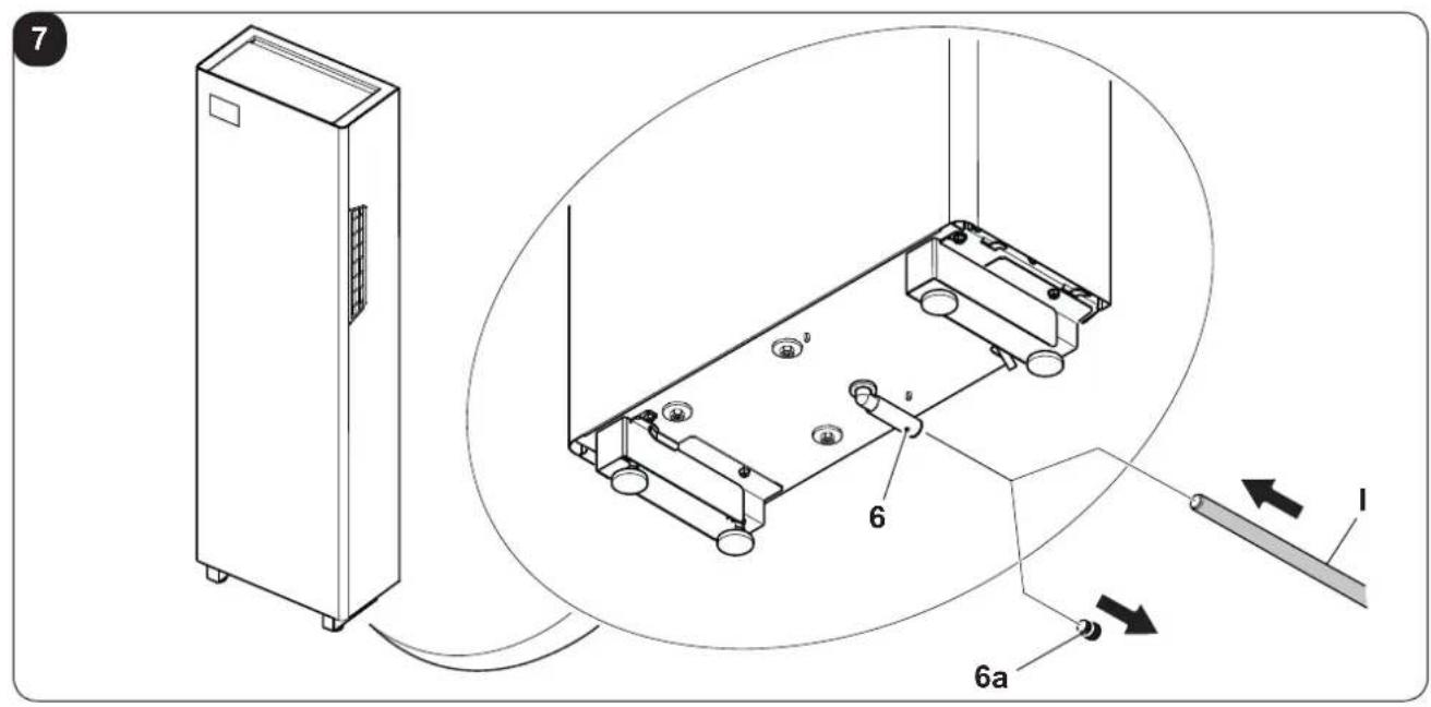
- For the machines with heat pump, the condensate drain pipe must be connected to the air conditioner (fig. 1 - ref. I) (supplied).
The condensate drain pipe (I) can be connected to the fitting (6), which is accessed after having opened the door under the unit and having removed the cap (6a). (Fig.7)
Alternatively, the condensate drain pipe (I) can be connected directly to the internal fitting (11) after having removed the rear panel.
In this case, operate as follows:
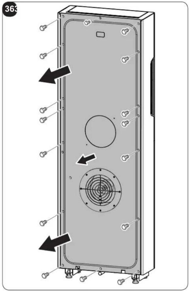
- Loosen the screws on the rear panel and remove it (Fig.36)
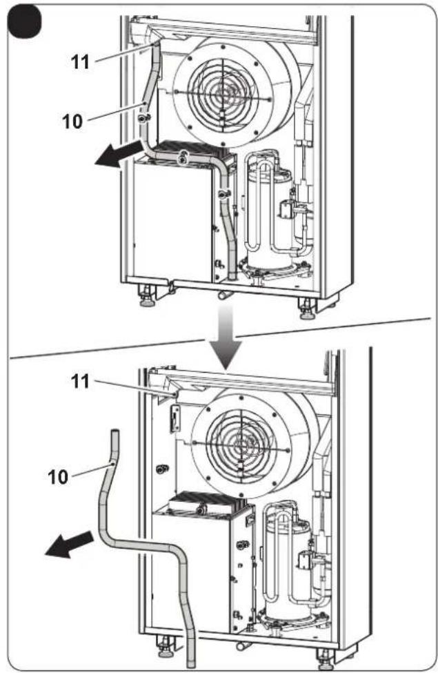
- Remove the condensate drain pipe (10) from the internal fitting (11). (Fig. 37)
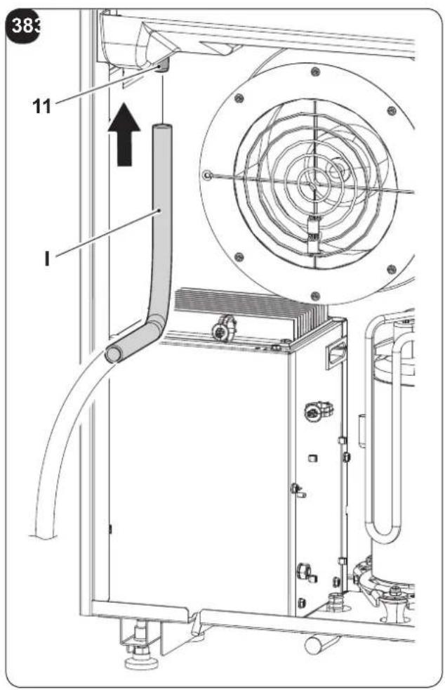
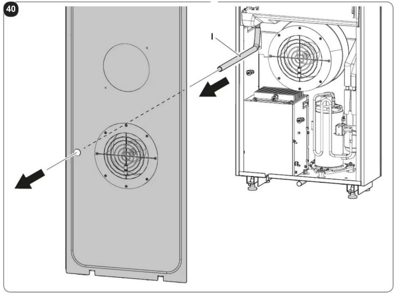
- Connect the condensate drain pipe (I) supplied to the internal fitting (11). (Fig. 38)
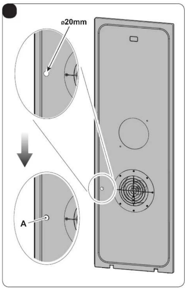
- Remove the insulation in correspondence with hole A present in the rear panel. (Fig. 39)
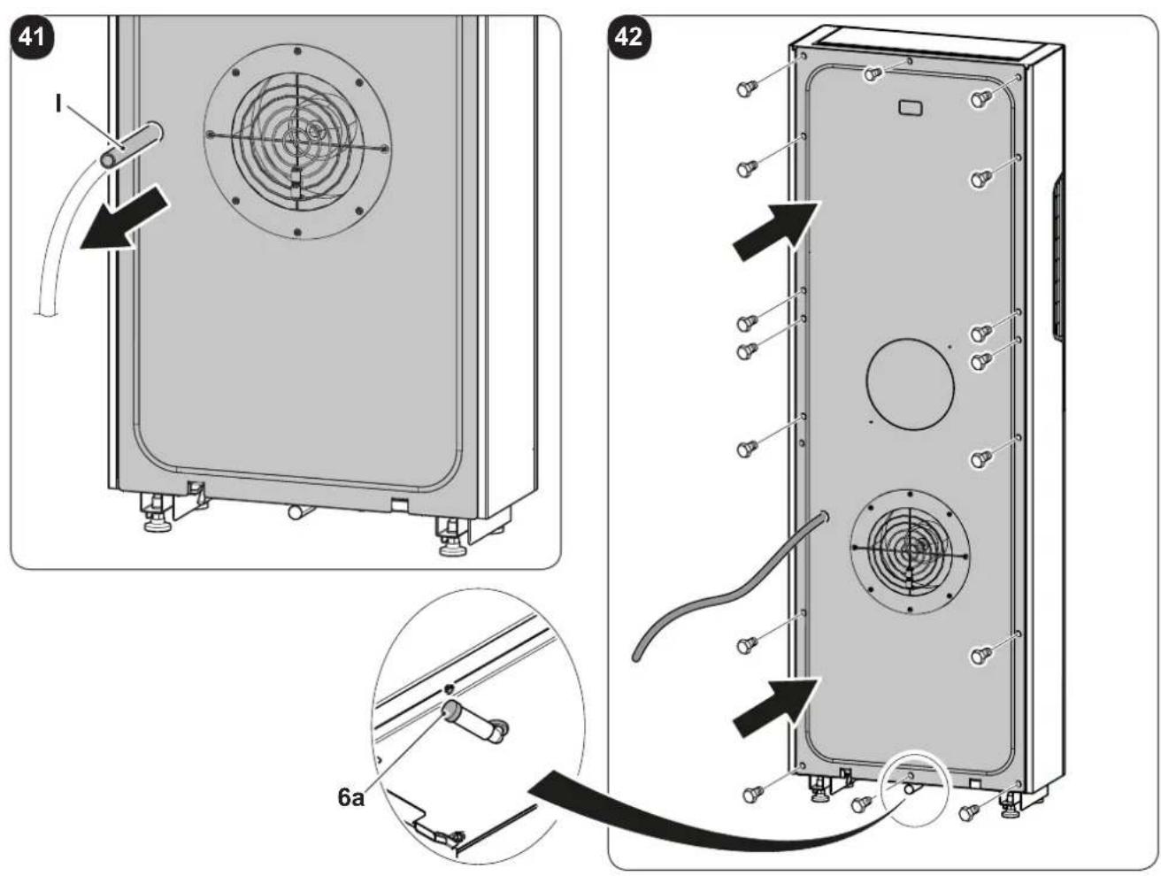
- Insert the condensate drain pipe (I) in the hole of the rear panel. (Fig.40-41)
- Tighten the rear panel screws and re-mount it. (Fig.42)
Check that the cap (6a) in the drain nipple is inserted. (Fig.42)
When the max level is reached, a solenoid valve ensures the condensate will flow out from the internal tray.
- For cold-only machines, connect the condensate discharge pipe if you intend running the unit at low outdoor temperatures (lower than 23°C).
- Since condensate drains by gravity, there must be a minimum slope of at least 3% at every point of the discharge line. Use a rigid or flexible tube having an inside diameter of at least 16~mm .
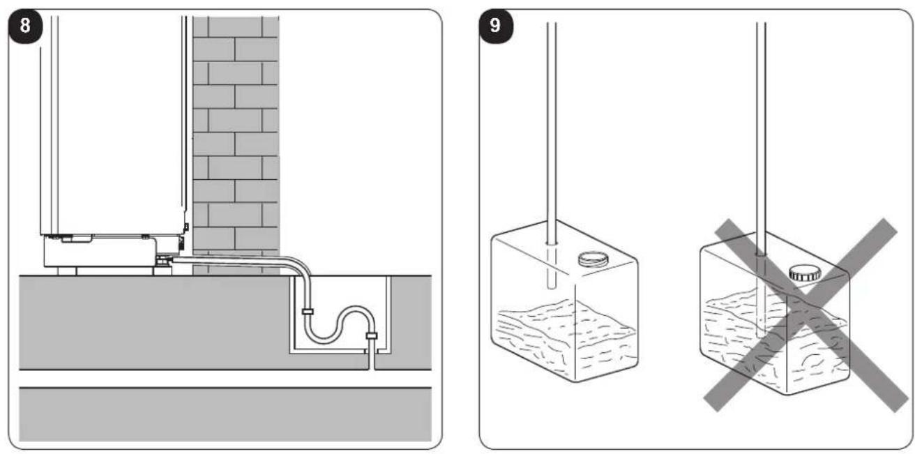
- If the line empties into a sewerage system, install a siphon before the point in which the pipe reaches the main discharge, at least 300 mm below the inlet from the unit (fig. 8).
- If the drainpipe drains into a vessel (tank or other container), this container should not be sealed and the drainpipe should not remain immersed in the water (see fig. 9).
- The hole through which the condensate pipe passes should always slope towards the outside (see fig. 10).
The exact position in which to place the pipe inlet, as compared to the machine, is shown on the drilling template.

Make sure, in this case, that the water expelled outward does not damage or disturb persons or property.
During the winter this type of drainage may cause sheets of ice to form.

When the condensate drainage is fitted, pay much attention not to compress the rubber hose.

In the event of operation during the winter with temperatures equal to or lower than 0^ C, make sure that the condensate drain pipe is protected from freezing in order to ensure draining.
In the event of prolonged operation during the winter with temperatures below 5^ C, install the optional basin heater kit.
2.4.3 - Assembly of the air ducts and external grids
- After drilling the holes (with the core drill), insert the plastic sheet (G) supplied with the air conditioner (fig. 11) inside them.
For the 162 mm holes, cut 130 mm from the long side of the sheet (G) (fig. 11).

The sheets must be 65 mm shorter than the length of the wall.
- Roll the sheet (G) and insert it into the hole, paying attention to the splicing line, which must always face upwards. (fig.12).
Use an ordinary cutter for the foregoing operation (fig. 12).
To position the external grids, proceed as follows:
a. Apply the seal (F) to the wall flange (D), ensuring it lines up with the outer edge of the flange as indicated in the figure 13.
b. Fix the two flanges using 2 pegs having a diameter of 6 mm and check that the two fixing holes are horizontal (fig. 14 - 15 - 16).
c. Fit the small eyelet of the spring, with the long stem, on the cap pin (on both components) (fig. 17).
d. Insert the two caps (with spring), on the front part of the external grid, on its two housings, pulling until it clicks (fig. 18) and couple the two chains to the large eyelet of the spring.
e. Using one hand, grip the two chains connected to the grid;
f. Bend the external grids back, gripping them with your free hand where they bend, and insert your fingers inside the single fins (fig. 19).
g. Insert your arm into the pipe until the grid protrudes completely outwards.
h. Reopen the grid, being careful to keep your fingers inside the fins.
i. Turn the grid until the fins are fully horizontal and tilted downwards.
I. Pull the chain, tensioning the spring, and couple the chain ring to the pin of the inner flange through which the pipes pass (fig. 20).
m. Use hand shears to cut off any excess chain links.

Use exclusively the supplied grids (E), or grids with like characteristics.
2.4.4 - Positioning the appliance on the anchorage bracket (anti-tip over device).
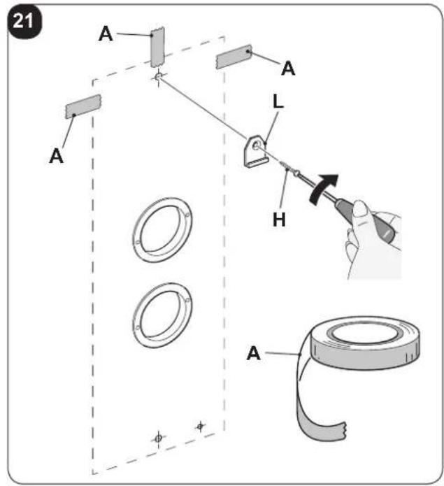
Operating on the previously-made hole (see fig. 6), fix the support bracket (L) to the wall using the plug screw (H) supplied (fig. 21).
After checking .....
.... that the fixing bracket is well-anchored to the wall,
.... that the installation site has been prepared for electrical connection and condensation discharge,
it is possible to hook the air conditioner.
EN - 14
Work as follows:
a. Apply adhesive tape (A) to the wall in order to have references to the unit attachment point (fig. 21).
The tape can be removed once the unit is attached to the wall.
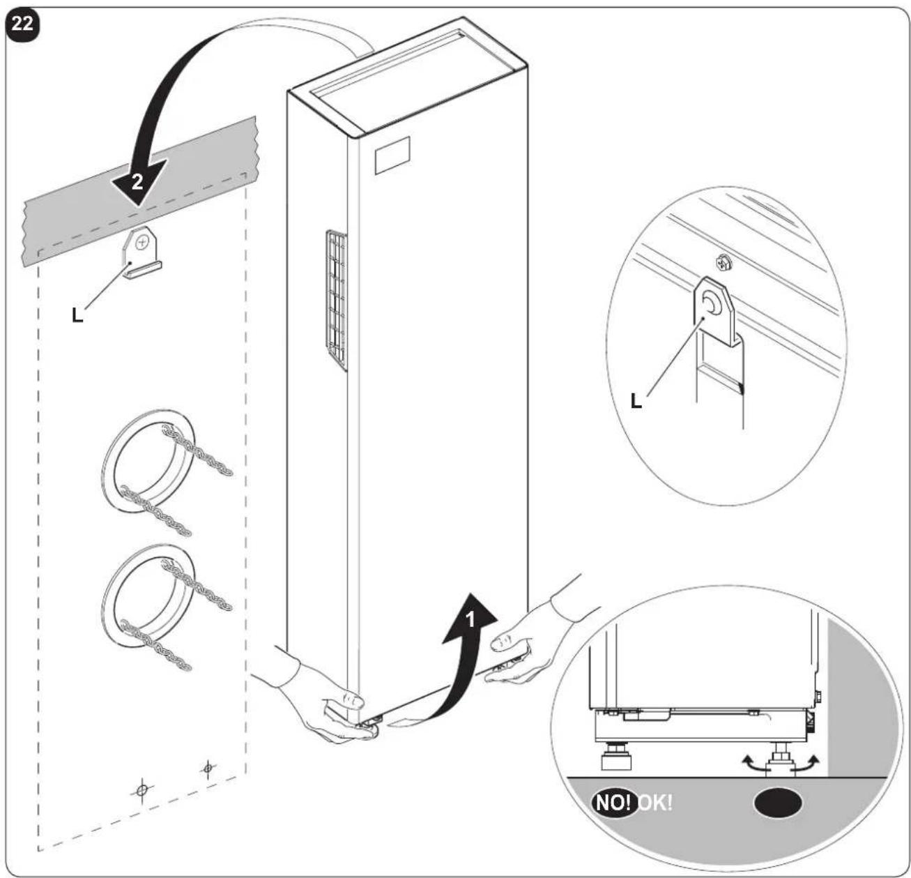
b. Lift the air conditioner by gripping it on the sides of the base and attach it to the bracket (L) (fig. 22).
Slightly tilt the lower part of the appliance towards yourself to ease the operation.
c. Adjust the appliance feet, making sure that they rest on the floor (fig.22)
d. Mount the aesthetic covers (N) on the adjustable feet. (Fig.35)

- To make the electrical connection and fasten the drainpipe, place a wedge between the air conditioner and the wall.
- When you have finished, inspect carefully to make sure there are no fissures at the back of the air conditioner (the insulating gasket must fit firmly against the wall) particularly in the zone where air enters and leaves the machine.
2.4.5 - Electric hook-up
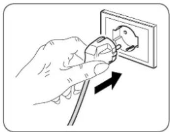
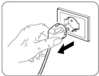
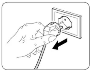
The appliance is fitted with a power cord with plug (Y-type connection).
If the socket is in proximity to the appliance, simply plug it in.
natural_image
Illustration of a hand using a power plug to install an electrical socket (no text or symbols present)
Before connecting the conditioner, ensure that:
e power supply voltage and frequency values comply with those indicated on the data plate of the appliance.
- The power supply line is fitted with an efficient earth connection that is appropriately sized for the maximum absorption of the conditioner (minimum cross-section of the cable must be 1.5 mm^2 ).
- The appliance is powered exclusively through a socket that is compatible with the plug supplied.

Any replacement of the power cable must be carried out solely by authorized technical support or by similarly qualified personnel.

On the power supply line of the appliance there must be an adequate omnipolar disconnection device that complies with the national installation regulations.
It is, however, necessary to check that the electrical power supply is equipped with efficient earthing and with adequate protections against overloading and/or short circuits (a type 10 AT delayed fuse or other devices with equivalent functions are recommended).
2.5 - ENERGY BOOST/SYSTEM ENABLE CONTACT INPUT
IT IS possible to connect a voltage-free presence contact (not supplied), to enable the ENERGY BOOST or SYSTEM ENABLE functions.
When the contact opens, the PI °C room temperature selected is increased (in cooling mode) or decreased (in heating mode).
The appliance is deactivated (stand-by) when the contact opens with PI set at 0°C.
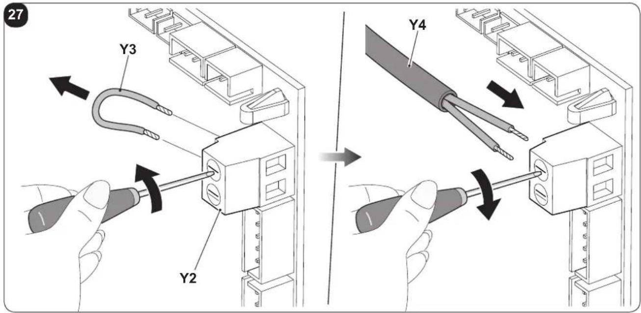
The presence contact must be connected to the terminal (Y2) on the main board (Y1) of the air conditioner (fig. 26).
Configuration:
a. Insert the plug in the power socket to power the air conditioner, then make sure the latter is switched to stand-by mode.
b. On the control panel, press the key MODE for more than 10 seconds until an acoustic signal is emitted.
c. The display shows the parameter P0.
d. Release the key MODE and press it again until you select the parameter PI.
e. Release the key MODE and press it again for 2 seconds.
f. Press keys + or - to select the desired configuration.
g. With value PI = 0, the input works from SYSTEM ENABLE.
When the contact opens, the air conditioner is forced in stand-by mode.
When the contact closes, the air conditioner restores its previous operation condition.
h. With value PI ≠ 0, the input works from ENERGY BOOST.
When the contact opens, the display shows the code E, desired temperature is reduced by PI °C if the air conditioner is in cooling mode or increased by PI °C if the air conditioner is in heating mode.
When the contact closes, the air conditioner restores its previous operation condition
The input ENERGY BOOST has no effect when the air conditioner is in fan, dehumidifier or automatic modes.

- This operation must be performed only by the installer or any similarly qualified personnel and in compliance to the current national regulations.
- To prevent the risk of an electric shock it is mandatory to switch off the main switch before performing the electrical connections or any maintenance operation to the appliances.
Proceed as follows to connect the voltage-free contact, of any presence contact (not supplied):
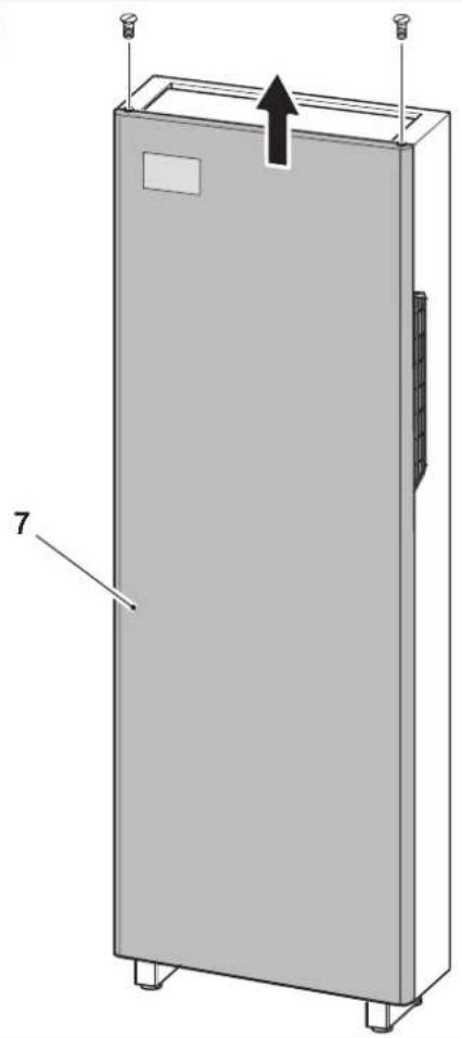
a. Remove the two clamping screws on the front panel and the front panel itself (7). (fig. 23).
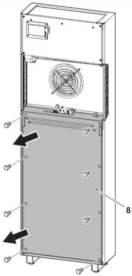
b. Loosen the eight clamping screws to remove the compressor compartment cover panel (8) (fig. 24).
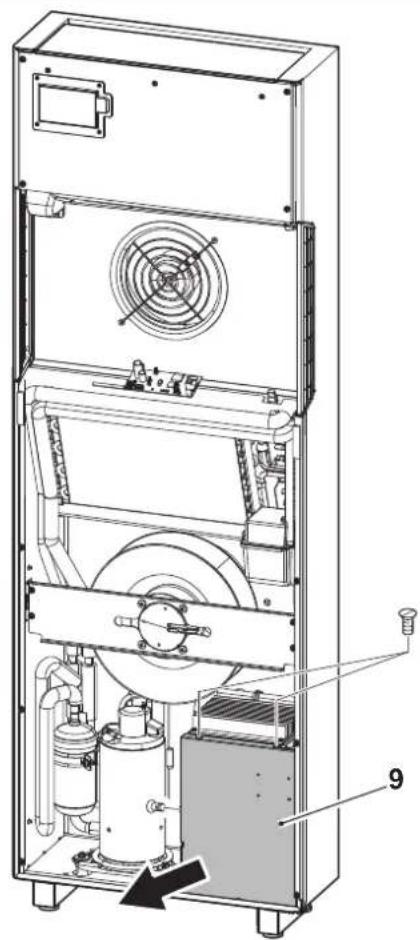
c. Loosen the three clamping screws to remove the electric control board cover (9) (fig. 25).
d. From the screw terminal (Y2), replace the jumper supplied (Y3) with the two wires of the presence contact (Y4). (fig. 27).
e. Close the electric control board by re-mounting the cover (9).
f. Re-mount the machine panels (7-8).
The input must be piloted by a potential-free dry contact.

Do not use a cable longer than 10 meters.
2.6 - ACCESSORIES B1014, B1012, B1015
In case of installation of the accessories B1014 serial interface and/or B1012 wireless wall control, it is necessary to disable display visualization from the remote control (key B11) during configuration phase.
When using the accessories B1014 and/or B1012, it is not possible to control the air conditioner neither from the remote control nor from the keys on the air conditioner console. For connection of the B1015 kit, refer to the relative manual inside the kit itself.
EN - 16

OLIMPIA SPLENDID
3 - USE
3.1 - WARNINGS

The installation and electrical connection of the air conditioner should be carried out by specialized personnel who possess the requisites set forth by law.
The installation instructions are contained in the appropriate paragraph of this manual.

No structural object (furniture, curtains, plants, leaves, blinds, etc.) should ever obstruct the normal flow of air from either the internal or external gratings.

- Never lean on the air conditioner body for any reason whatsoever, to prevent serious damage to the external parts.
- Do not move the air outlet flap by hand. Always use the remote control to adjust baffle position.
- If the unit leaks water, switch it off immediately and disconnect it from the power mains. Call the nearest service centre.
- When the air conditioner is heating, it has to periodically eliminate any ice that could form on the external battery. While it is doing this, the machine keeps running but does not heat the room. This lasts for a brief period of time, from 3 to a maximum of 10 minutes.
- Clean the air filter periodically, as described in the specific paragraph (4.1.2).

The air conditioner must not be installed in rooms where explosive gasses develop or where there are conditions of heat and humidity beyond the maximum limits indicated in the installation manual.
3.2 - DESCRIPTION OF THE WARNING PANEL
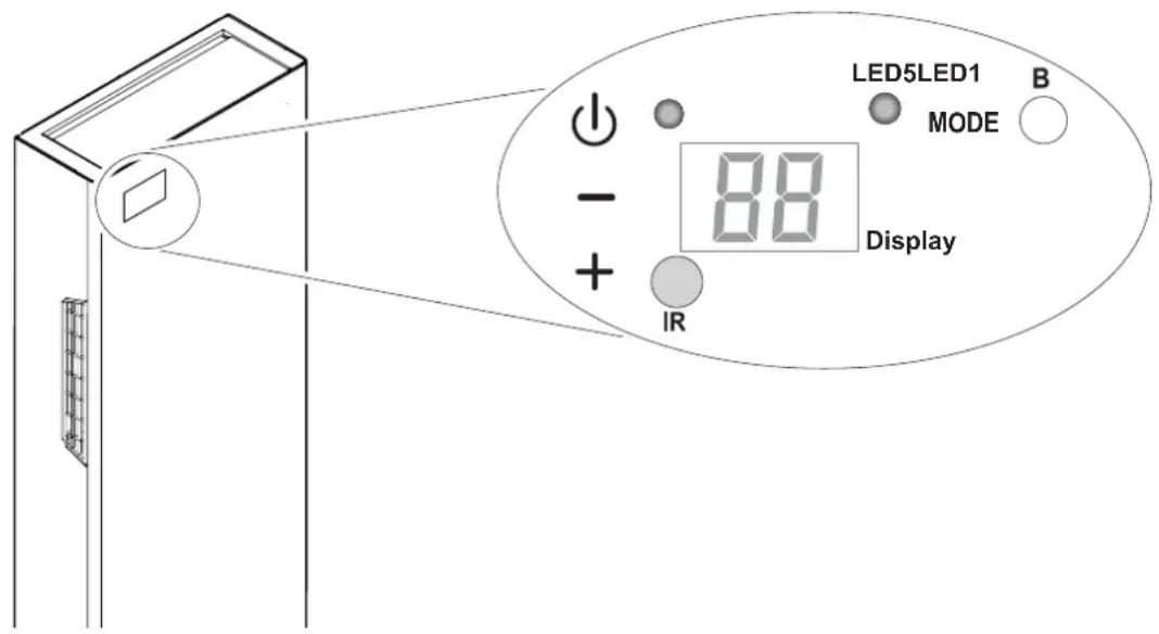
In the upper right part of the appliance are located a few keys and LEDs whose functions are described below.

EN - 17
Keys
Before performing the following operations, press one of the keys to enable the console.
- Increase in the desired temperature (maximum value settable is 30^ C/86°F).
- Decrease in the desired temperature. (minimum value settable in heating mode is 16^ C/ 61^ F, in cooling mode is 18^ C/ 64^ F).
Activation/deactivation (Stand-by) of the air conditioner and ventilation speed selection.
- Brief tap to select minimum, medium, maximum or automatic speed.
- Prolonged press for activation/deactivation (Stand-by).
MODE Operation mode selection and parameters setting
- Brief tap (for more than 2 seconds) to select ventilation, cooling or heating operation modes
- Prolonged press to enable parameters setting if in Stand-by mode
+ and - To be pressed simultaneously for at least 5 seconds to enable/disable the keypad lock function


and MODE To be pressed simultaneously and for an extended period of time (at least 5 seconds) to set to zero the filter dirty report
Others
IR Infrared receiver
B Buzzer
3.3 - CONTROL PANEL NOTIFICATIONS
The console includes the notifications listed below.
| OPERATING CONDITIONS DISPLAY | LED5 | LED1 | |
| Stand-by | OFF | OFF | OFF |
| Cooling mode | 18 ÷ 30^/64 ÷ 86^ | ONBLUE | X |
| Heating mode | 16 ÷ 30^/61 ÷ 86^ | ONRED | X |
| Dehumidification mode | -- | ONBLUE | X |
| Ventilation mode | -- | OFF | X |
| Automatic mode | R | X | X |
| Maximum ventilation speed | HI | X | X |
| Medium ventilation speed | NE | X | X |
| >>> | |||
EN - 18
| OPERATING CONDITIONS DISPLAY LED5 LED1 | |||
| Minimum ventilation speed | Lo | X | X |
| Automatic ventilation speed | Ru | X | X |
| Timer enabled X X ON | |||
| [6XX] Filter dirty report* | F1 | X | X |
| Energy Boost contact opening (par. PI>0) | E | X | X |
| System Enable contact opening (par. PI=0) | P | OFF OFF | |
| Keypad locked | bL | X | X |
| Top/Bottom wall configuration parameter | PO | OFF OFF | |
| Ceiling installation | uP | OFF OFF | |
| Floor installation | dO | OFF OFF | |
| * Reset as described in paragraph 3.2 | |||
3.4 - USE OF THE REMOTE CONTROL
The remote control supplied with the air-conditioner is the instrument that enables you to use the appliance in the most convenient way.
It should be handled with care and in particular:
- Keep it dry (do not clean it with water or leave it outdoors in bad weather).
- Avoid dropping or bumping it.
- Keep it out of direct sunlight.
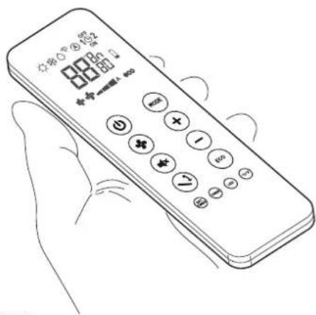

• The remote control operates by means of an infrared beam.
- During use, there must not be any obstacle between the remote control and the air-conditioner.
- If other appliances in the room have remote controls (TV, stereo, etc...), there may be interference with consequent loss of the sent signal.
- Electronic and fluorescent lights may also interfere with transmissions between remote control and air-conditioner.
- Remove the batteries in case of prolonged disuse of the remote control.
- The remote control display goes off after a few seconds of non-use, to reactivate it press any key.
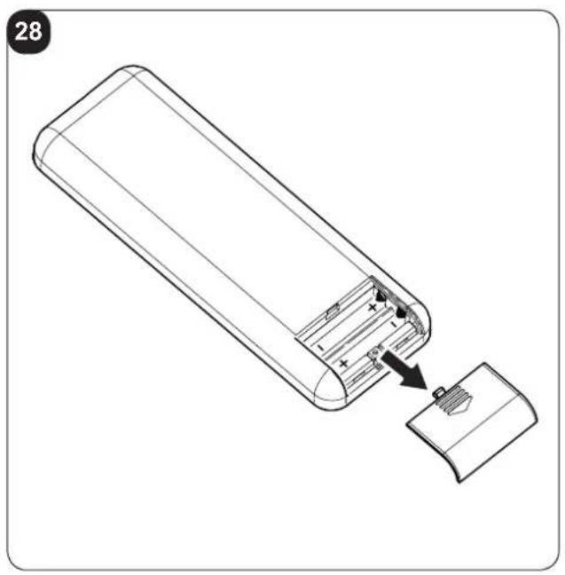
3.4.1 - Insertion of batteries
The batteries are supplied with the machine.
To insert the batteries correctly (figure 28):
a. Remove the batteries compartment cover.
b. Insert the batteries into the relevant compartment.

Check the polarity indicated on the bottom of the compartment. (Fig.29)
c. Close the compartment correctly (fig. 29).
3.4.2 - Replacement of batteries
The batteries should be replaced when the display on the remote control does not appear sharply or when the remote control does not change the settings.

Always use new batteries and replace both at the same time.
The use of old or different batteries could generate malfunctioning of the remote control.
The remote control uses two dry alkaline 1.5V batteries (AAA.LR03).
When the batteries have been replaced, adjust the remote control clock.

When replacing batteries, replace both and dispose of the dead batteries in the appropriate collection centres and as required by law.
- If the remote control is not used for several weeks or longer, remove the batteries.
Any leaks from the batteries could damage the remote control. - The average life-span of the batteries, with normal use, is approx. six months. Replace the batteries when the indoor unit command receipt "beep" can no longer be heard, or if the transmission indicator on the remote control does not switch on.

Do not re-charge or disassemble the batteries. Do not throw the batteries into the fire. Can burn and explode.

If the battery liquid falls onto the skin or clothes, wash well with clean water. Do not use the remote control with batteries that have leaked.
The chemical products contained in the batteries can cause burns or other risks to health.
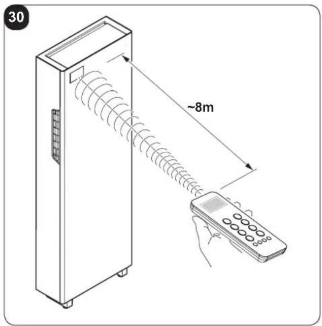
3.4.3 - Location of the remote controller
- Keep the remote control in a position from which the signal can reach the appliance receiver (maximum distance is about 8 meters - with charged batteries) (fig. 30).
The presence of obstacles (furniture, curtains, walls, etc.) between the remote control and the appliance reduces the remote control range.
EN - 20
3.5 - DESCRIPTION OF REMOTE CONTROL
The remote control is the interface between the air-conditioner and the customer, so it is very important to learn all its functions, the use of the various controls and the meaning of the symbols marked on it.
3.5.1 - Description of the remote control keys
B1 Activation/deactivation (Stand-by) of the unit
B2 Minimum, medium, maximum or automatic ventilation speed selection
B3 Activation/deactivation of the function SILENT
B4 Activation/deactivation of the oscillation function of the air outlet flap
B5 Operating mode selection
- cooling > heating > ventilation >
dehumidification > automatic
B6 Desired/clock/programming temperature increase
B7 Desired/clock/programming temperature decrease
B8 Activation/deactivation of function ECO
B9 Clock/programming setting
B10 Activation/deactivation of the functions programming 1 / programming 2
B11 Activation/deactivation of the display on board of the machine switching on
B12 Desired temperature unit selection °C/°F
B13 Activation/deactivation of the report console display
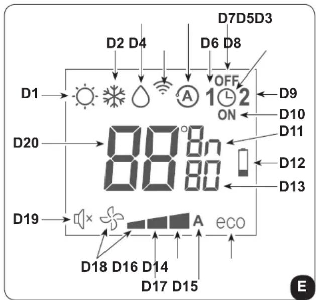
3.5.2 - Description of the remote control display
D1 Heating mode
D2 Cooling mode
D3 Dehumidification mode
D4 Transmission of the command in progress
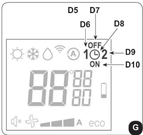
D5 Automatic mode
D6 Program 1
D7 Program switching off time setting
D8 Clock/program setting
D9 Program 2
D10 Program switching on time setting
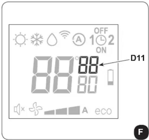
D11 Temperature/time unit of measurement
D12 Low battery notification
D13 Minutes timer
D14 ECO function enabled
D15 Automatic ventilation speed
D16 Maximum ventilation speed
D17 Medium ventilation speed
D18 Minimum ventilation speed
D19 Function SILENT enabled
D20 Desired temperature/clock/programming
3.6 - DESCRIPTION OF THE AIR CONDITIONER FUNCTIONS
3.6.1 - Main switch-on and running management
• System management is possible using the remote control.
In order to transmit commands to the indoor appliance, point the front of the remote control toward the appliance's control panel.
The device emits a beep when it receives a command.
- The maximum distance from which the appliance can be controlled is about 8 meters (with charged batteries).
3.6.2 - ECO key
- Press B8 on the remote control to activate the energy conservation function, automatically optimizing the machine features (on the display symbol D14 appears).
3.6.3 - Turning the unit ON/OFF
- Press key B1 on the remote control to activate or deactivate (stand-by) the air conditioner. The control system of the unit is equipped with memory, for this reason all the settings won't be lost when shutting off the appliance itself.

In case of prolonged stop of the machine, it must be deactivated turning the main switch off or unplugging the machine from the mains.
3.6.4 - Operation in "Cooling" mode only
- When used in this mode, the air conditioner dehumidifies and cools the room.
- To activate this mode, press several times the key B5 on the remote control until when the symbol D2 appears on its display.
• This mode can also be activated via the signal console buttons (Fig.B).
- In this run mode, the required temperature and fan speed can be set. After three minutes (as a maximum) from activation in this operating mode the compressor will start and the appliance starts emitting cold air.
3.6.5 - Operation in "Dehumidification" mode only
- When used in this mode, the air conditioner eliminates the humidity in the room.
This function can be extremely useful between seasons, particularly on rainy days when the temperature is not uncomfortable but the excess humidity feels unpleasant. - In this mode, both room temperature and fan speed settings are ignored, which correspond to minimum.
• Any fan temperature and speed indication then disappears from the display of the control panel (fig.C).
- To activate this mode, press several times key B5 on the remote control until when symbol D3 and the automatic ventilation symbol D18 (fan + first notch) appear on its display.
• In this operating mode it is normal for the air conditioner to function intermittently.
3.6.6 - Operation in "Ventilation" mode only
- When used in this mode the air conditioner does not perform any action with regard to temperature and air humidity in the room.
- To activate this mode, press several times key B5 on the remote control until when the automatic ventilation symbol D18 (fan + first notch) appears on its display.
• This mode can also be activated via the signal console buttons (Fig.B).
3.6.7 - Operation in "Spa" mode only (Automatic)
- In this mode, the machine's temperature is automatically regulated according to the room's temperature. The fan speed is also automatically regulated according to the set temperature (except in dehumidification mode).
- To activate this mode, press several times key B5 on the remote control until when symbol D5 appears on the display.
3.6.8 - Operation in "Heating" mode only
• Using this mode, the appliance heats the room.
- To activate this mode, press several times key B5 on the remote control until when symbol D1 appears on its display.
• This mode can also be activated via the signal console buttons (Fig.B).
- In this run mode, the required temperature and fan speed can be set. After three minutes (maximum time) the compressor should start and the air conditioner starts heating the room.

The air conditioner has to defrost its battery periodically.
During this operation the air conditioner does not heat the room, though its internal parts remain on except for the room air fan. when the outdoor temperature is very low, there may be a slight delay for passage from the minimum to the medium or maximum speed from when the command is sent to the machine with the remote control.
Like delays might occur on activating the swinging function of the mobile baffle.
After having turned off the unit, the internal fan runs seconds more. Then it stops and both air flaps close.
EN - 23
3.6.9 - Checking airflow direction
- Press key B4 on the remote control to activate/deactivate the continuous oscillation of the moving air outlet deflector (fig.A - ref. 1).
- When continuous oscillation is active, an additional press of the key B5 allows to lock the deflector so as to obtain the desired vertical direction for the air flow.

The moving deflector position must never be forced manually.
• The fan speed check occurs through key B2 (on the remote control).
- Pressing several times this key will cause speed to change according to the following sequence:
Low > Medium > High > Automatic.
• The higher the speed setting, the greater the output of the air conditioner but also the louder its operation.
- By setting the Automatic mode, the onboard microprocessor adjusts the automatic speed. The higher the difference between the room temperature detected and the temperature set, the higher the speed.
• As the room temperature nears the setting, fan speed is reduced automatically.
- In dehumidification mode, it is not possible to control the speed as the appliance can only operate exclusively at low speed.
3.6.11 - SILENT key
• To activate this mode, press key B3 on the remote control (symbol D19 appears on the display).
- The activation of the function SILENT allows to obtain multiple results:
- gradual increase in the set temperature during cooling mode
- gradual decrease in the set temperature for heating (HP versions only)
- reduction of the sound level of the appliance
- reduction of ventilation speed
- To activate the function SILENT, it is necessary to select the operating mode and the desired temperature first, then press key B3 to activate it.
- Noise reduction involves the machine noise and cooling/thermal power optimization. If, in certain moments, cooling/thermal power is insufficient, disable the function SILENT.
3.6.12 - Timer setting
- The appliance logic allows the User to make use of two different timer programs (see paragraph 3.6.14), thanks to which the appliance can be deactivated and activated (or vice versa) whenever desired (for example, it can be activated shortly before returning home so as to find an already pleasant temperature in the room).
- Firstly, if it is desired to make use of these functions, set the correct time (see paragraph 3.6.13) and then set the timer as you prefer.
3.6.13 - Timer and clock setting
To set time, work with the remote control as follows:
a. Press key B9 (SET TIMER) until when the hour indication h (D11) appears on the display
b. Set the hour with keys B6 (+) and B7 (-).
c. Press the key B9 until when the minutes indication m (D11) appears on the display.
d. Set the minutes with keys B6 (+) and B7 (-).
e. Press key B9 to save the time and proceed with the timer programming.
3.6.14 - Timer setting
(PROGR. 1 and PROGR. 2)
It is possible to set one or both the timer programs.
To set the appliance activation and deactivation times in the two programs, use the remote control and work as follows:
a. Press once or more key B9 (SET TIMER) until when symbol 1 (D6) (Activation time of the 1° program) and symbol ON (D10) appear on the display.
b. Use keys B6 (+) and B7 (-) to increase or decrease the hour in which you wish the air conditioner activates. The hour variation settable with keys B6 (+) and B7 (-) is of 30 minutes.
c. Press key B9 (SET TIMER) a second time; symbol 1 (D6) (Deactivation time of the 1° program) and symbol OFF (D7) appear on the display.
d. Use keys B6 (+) and B7 (-) to increase or decrease the hour in which you wish the air conditioner switches off. The hour variation settable with keys B6 (+) and B7 (-) is of 30 minutes.
e. Press key B9 (SET TIMER) again; symbol 2 (D9) (Activation time of the 2^ program) and symbol ON (D10) appear on the display.
f. Use keys B6 (+) and B7 (-) to increase or decrease the hour in which you wish the air conditioner activates.
The hour variation settable with keys B6 (+) and B7 (-) is of 30 minutes.
g. Press key B9 (SET TIMER) again; symbol 2 (D6) (Deactivation time of the 2^ program) and symbol OFF (D7) appear on the display.
h. Use keys B6 (+) and B7 (-) to increase or decrease the hour in which you wish the air conditioner switches off. The hour variation settable with keys B6 (+) and B7 (-) is of 30 minutes.
i. To return to the normal operation mode, press once or more key B9 (SET TIMER) until when all the symbols related to this setting on the display turn off.
EN - 25
3.6.15 - Timer activation and deactivation
Once set, the timer programs can either be activated or deactivated depending on occasional needs.
Activation may relate to one of the two programs or both.
In particular, each time you press key B9 (SET TIMER) (Programs activation), situation changes as follows:
• Use of Program no. 1 only.
• Use of Program no. 2 only.
• Use of Programs 1 and 2.
• Disuse of both programs.
3.6.16 - Reset of all the remote control functions
Replacing the batteries or removing them even for a few instants will cause all the settings of the remote control to be reset.
In so doing, all the time settings of the timer saved in the remote control are cancelled and the remote control restores all the factory settings.
3.6.17 - Managing the unit if the remote control is not available
In case of loss or malfunction of the remote control and/or exhaustion of the batteries, the appliance can be controlled from the keys on board of the machine.
3.7 - RECOMMENDATIONS FOR ENERGY SAVINGS
Below find simple recommendations for reducing consumption:
• Always and constantly keep the filters clean (see maintenance and cleaning chapter).
- Keep the doors and windows of the rooms to be climate controlled closed.
- Avoid the sun's rays penetrating freely into the room (we recommend using curtains or lowering blinds or closing the shutters).
- Do not obstruct the unit air flow (inlet and outlet), i.e. in addition to bad performance of the system, it also affects correct operation and the possibility of irreparable faults to the units.
4 - MAINTENANCE AND CLEANING

Before proceeding with any maintenance and cleaning, always make sure the system has been switched off, using the remote control, and the power supply plug has been disconnected from the system socket (or the upstream master isolating switch is positioned at "0" OFF).
natural_image
Illustration of a hand using a power plug to insert an electrical socket (no text or symbols)
Do not touch the metal parts of the unit when removing the air filters. They are very sharp. Cuts or injury risk.
4.1 - CLEANING
4.1.1 - Appliance and remote control cleaning
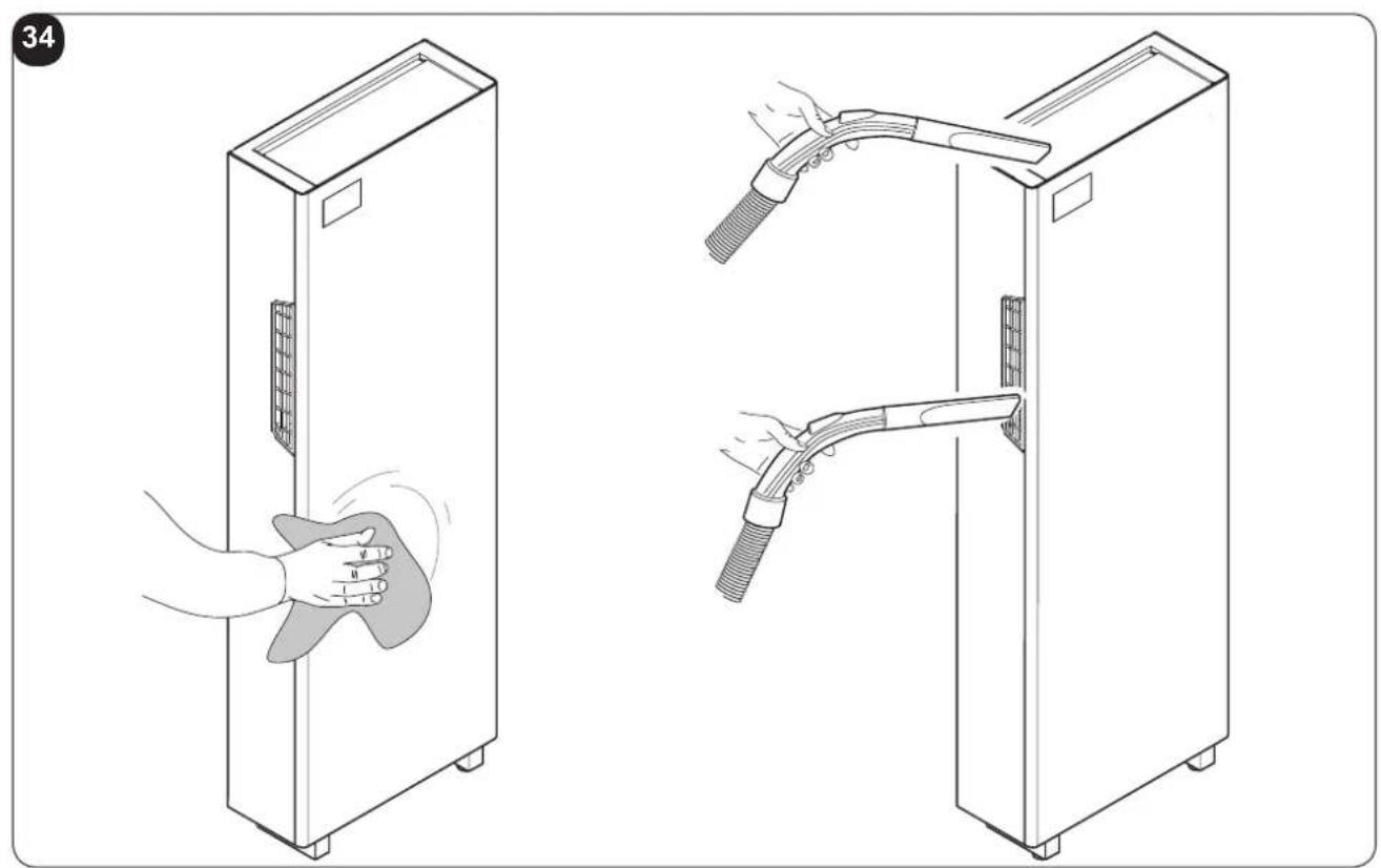
Use a dry cloth to clean the appliance and the remote control (fig. 34).
It is possible to use a cloth moistened with cold water to clean the appliance if it is very dirty.
Suck between the air inlet and outlet grilles (fig. 34).

Do not use a chemically treated or antistatic cloth to clean the appliance. Not use gasoline, solvent, polish or similar solvents.
These products could cause the breakage or deformation of the plastic surface.
4.1.2 - Cleaning the air filters
In order to guarantee effective indoor air filtration and good working order of your air conditioner, it is essential to clean the air filters periodically.
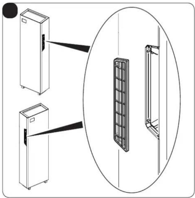
The air filters are in the left and right sides of the appliance. (Fig.31)
natural_image
Illustration of a hand inserting a plug into an electrical outlet (no text or symbols)Filters extraction (Fig 32):
a. Switch the unit off and wait for the delivery flaps to close.
b. Electrically disconnect the appliance.
c. Hold the top part of the grid (3) with two fingers.
d. Remove the grid (3). including the filter.
e. Perfectly wash and dry all the filters.
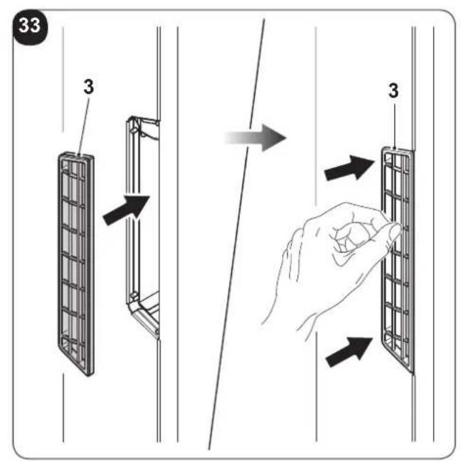
Re-mounting the filters:
f. Re-mount the grids (3) including filter. The grids (3) are fixed via magnets. (fig. 33).
To cancel the dirty filters signal, after having connected the air conditioner to the mains, simultaneously press the Stand-by and MODE keys, present on the control panel, for at least 5 seconds (see figure B).
This way the dirty filter signal is removed and the related count is set to zero.
EN - 27
4.2 - MAINTENANCE
If you plan to idle the unit for a long time, perform the following:
a. Stop the air conditioner and disconnect the power supply.
b. Remove the batteries from the remote control.

Do not perform them alone.
4.2.1 - Routine maintenance
The air conditioner that you have purchased has been designed to reduce routine maintenance operations to a minimum.
These operations involve solely the cleaning operations outlined below:
- Cleaning or washing of the ambient air filter every 2 weeks or every time the relative red LED lights up (this can be done by the user, see user manual).
• Cleaning of the condensing battery and cleaning of the condensate management system.
These operations must be carried out by skilled technicians on a regular basis that will depend on the place of installation and intensity of use.
Depending on the quantity of dirt, the unit can be cleaned dry (by using a battery compressor and bowl and cleaning the fins with a soft brush taking care not to deform them) or more thoroughly using dedicated detergents.
Before you leave the site of installation you should gather up all packing material and use a damp cloth to remove any traces of dust that may have deposited on the machine during assembly (fig. 34).
These operations, though certainly not essential, have a beneficial effect as they enhance the professional image of the installer in the eyes of the client.
To prevent unnecessary calls by the user, before you leave the site of installation
- it is also a good idea to:
- Explain the contents of the Instruction Manual to the user.
• Show the user how to clean the filter.
4.3.1 - Diagnosis of the inconveniences
It is important for the User to distinguish between functional problems and anomalies in relation to the behaviour of the appliance as foreseen for its normal operation. Furthermore, the most common problems may easily be solved through simple operations on behalf of the User (See paragraph: Anomalies and solutions).

For all the other reports (see paragraph: 4.3.3 - Console alarms), it is necessary to always contact the technical assistance service"

Any attempt to repair the appliance by unauthorised personnel will immediately invalidate any form of guarantee.
4.3.2 - Functional aspects not to be mistaken for anomalies
The following events may occur during normal operation:
a. The compressor does not start up again immediately after a stop (it takes about three minutes to start again).
- In the operating logic of the appliance a delay between a compressor stop and its successive restart has been included, so that the compressor itself is protected against activations that are too frequent.
b. During the heating operation of the heat pump appliances, the flow of hot air may occur some minutes after activation of the compressor.
- Should the fan start at the same time as the compressor, for the first few minutes it would emit cold air into the room (and this could bother the occupants) since the unit has not yet reached steady running conditions.
4.3.3 - Console alarms
If one of the following alarms on the display persists for more than three minutes, please contact an Olimpia's assistance centre.
| ALARM DESCRIPTION | DISPLAY ALARM CODE |
| External air temperature probe faulty 1 | |
| Condenser temperature probe faulty 2 | |
| Inlet temperature probe faulty 3 | |
| Compressor current protection 4 | |
| Communication error 5 | |
| Power line overcurrent 6 | |
| Compressor current protection not suitable 7 | |
| Power board DC voltage problem 8 | |
| Current anomaly 9 | |
| Condenser temperature too high 10 | |
| UIPM protection 11 | |
| EEPROM error 12 | |
| Inlet temperature too high 13 | |
| Room temperature probe faulty 14 | |
| Evaporator temperature probe faulty | 15 |
| Evaporator temperature too low | 16 |
| Evaporator temperature too high | 17 |
| Mains voltage problem | 18 |
| Evaporating fan motor failure | 19 |
| Water level alarm | 20 |
| EEPROM error 21 |
4.3.4 - Anomalies and remedies
| Malfunctioning Cause What must be done? | ||
| The unit will not start. Current failure | Wait for the current to be restored. | |
| The unit is disconnected from the current. | Check that the plug is inserted in the wall socket. | |
| Power switch is switched to “0” Press | the power switch when it is positioned on “1” (figure 37). | |
| The fuse is interrupted or the thermal-magnetic circuit breaker has tripped. | Replace the fuse or restore the thermal-magnetic circuit breaker. | |
| The remote control batteries may be discharged. | Replace the batteries. | |
| The time set with the timer may not be correct. | Wait or annul the timer setting. | |
| The appliance doesn’t cool/heat sufficiently anymore. | Incorrect temperature setting. Set the | temperature correctly. Consul the "Using the remote control" chapter for the procedure. |
| The air filter is dirty. Clean the air filter. | ||
| The doors or windows are open. Close the doors or windows. | ||
| The air inlet or outlet vents of the indoor or outdoor units are blocked. | First, remove the obstructions and then re-start the unit. | |
| The compressor 3 minute protection has activated. | Wait. | |
| The appliance works but the report console is always switched off. | The display has been set to OFF. Re | activate the display from the remote control. |
| The appliance works but the report console keys don’t work. | The keypad lock is active. Disable the keypad lock from the report console. | |
If the problem has not been solved, please contact the nearest technical assistance service. e give detailed information about the malfunction and on the equipment version. e give detailed information about the malfunction and on the equipment version. | ||
5 - TECHNICAL DATA

For the technical data listed below, consult the characteristic data plate affixed to the product.
• Power supply voltage
• Maximum power absorbed
• Maximum current absorbed
- Cooling capacity
- Refrigerant gas
• Protection rating of the casings
• Max. operating pressure
- Dimensions (Width x Height x Depth) ...... mm 903 x 520 x 215
• Weight (without packaging) ....kg☐56
| OPERATING LIMIT CONDITIONS | INDOOR TEMPERATURE | OUTDOOR TEMPERATURE |
| Maximum operating temperatures in cooling model | DB 35°C - WB 24°C DB 43°C - WB 32°C | |
| Minimum operating temperatures in cooling model | DB 18°C DB -10°C | |
| Maximum operating temperatures in heating model | DB 27°C DB 24°C - WB 18°C | |
| Minimum operating temperatures in heating model | --- DB -15°C |
EN - 32
TABLE DES MATIÈRES GÉNÉRALE
0 - MISES EN GARDE....3
0.1 - INFORMATIONS GÉNÉRALES....3
0.2 - SYMBOLOGIE 3
natural_image
Illustration of a hand using a power plug to install an electrical socket (no text or symbols present)
natural_image
Illustration of a hand using a power plug to insert an electrical socket (no text or symbols)
natural_image
Illustration of a hand inserting a plug into an electrical outlet (no text or symbols)- Poids (sans emballage)....kg ^56
natural_image
Illustration of a hand using a power plug to install an electrical socket (no text or symbols present)
natural_image
Hand inserting a plug into an electrical outlet (no text or symbols visible)
4.3 - DIAGNOSIS, ALARMAS E INCONVENIENTES....29
2 - INSTALACIÓN
natural_image
Illustration of a hand using a power plug to install an electrical socket (no text or symbols present)
natural_image
Hand inserting a plug into an electrical outlet (no text or symbols visible)