GDS 12V115 Professional - Screwdriver BOSCH - Free user manual and instructions
Find the device manual for free GDS 12V115 Professional BOSCH in PDF.
Download the instructions for your Screwdriver in PDF format for free! Find your manual GDS 12V115 Professional - BOSCH and take your electronic device back in hand. On this page are published all the documents necessary for the use of your device. GDS 12V115 Professional by BOSCH.
USER MANUAL GDS 12V115 Professional BOSCH
(15) Screwdriver bit
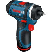
Accessories shown or described are not included with the product as standard. You can find the complete selection of accessories in our accessories range. Technical Data Cordless Impact Wrench GDR 12V-110 GDS 12V-115 Article number 3601JE00.. 3601JE01.. Rated voltage V= 12 12 No-load speed
0–2600 0–2600 Impact rate
Nm 110 115 Machine screw diameter mm M4–M12 M4–M12 Max. screw diameter mm 8 8 Tool holder ¼"internal hexagon ∎ 3/8" Weight according to EPTA-Procedure 01:2014
kg 0.92–1.2 0.91–1.2 Recommended ambient temperature during charging °C 0to+35 0to+35 1 609 92A 6PS | (14.09.2021) Bosch Power ToolsEnglish | 15 Cordless Impact Wrench GDR 12V-110 GDS 12V-115 Permitted ambient temperature during opera- tion
and during storage °C –20to+50 –20to+50 Recommended rechargeable batteries GBA 12V... GBA 12V... Recommended chargers GAL 12... GAX 18... GAL 12... GAX 18...
Measured at 20–25°C with rechargeable battery GBA 12V 2.0Ah. B) Depends on battery in use C) Limited performance at temperatures <0°C Noise/vibration information Noise emission values determined according to EN62841-2-2. Typically, the A-weighted noise level of the power tool is: Sound pressure level 87dB(A); sound power level 98dB(A). Uncertainty K=3dB. Wear hearing protection! Vibration total values a
(triax vector sum) and uncertainty K determined according toEN62841-2-2: Impact tightening of fasteners of the maximum capacity of the tool: a
The vibration level and noise emission value given in these instructions have been measured in accordance with a standardised measuring procedure and may be used to com- pare power tools. They may also be used for a preliminary estimation of vibration and noise emissions. The stated vibration level and noise emission value repres- ent the main applications of the power tool. However, if the power tool is used for other applications, with different ap- plication tools or is poorly maintained, the vibration level and noise emission value may differ. This may significantly increase the vibration and noise emissions over the total working period. To estimate vibration and noise emissions accurately, the times when the tool is switched off or when it is running but not actually being used should also be taken into account. This may significantly reduce vibration and noise emissions over the total working period. Implement additional safety measures to protect the oper- ator from the effects of vibration, such as servicing the power tool and application tools, keeping their hands warm, and organising workflows correctly. Assembly u Remove the battery from the power tool before carry- ing out work on the power tool (e.g. maintenance, changing tool, etc.). The battery should also be re- moved for transport and storage. There is risk of injury from unintentionally pressing the on/off switch. Battery Charging u Use only the chargers listed in the technical data. Only these chargers are matched to the lithium-ion battery of your power tool. Note: The battery is supplied partially charged. To ensure full battery capacity, fully charge the battery in the charger before using your power tool for the first time. The lithium-ion battery can be charged at any time without reducing its service life. Interrupting the charging process does not damage the battery. The lithium-ion battery is protected against deep discharge by the "Electronic Cell Protection (ECP)". When the battery is discharged, the power tool is switched off by means of a protective circuit: The application tool no longer rotates. u Do not continue to press the On/Off switch after the power tool has automatically switched off. The battery can be damaged. Removing the battery (see figure A) To remove the battery (8), press the release button (7) and pull the battery downwards out of the power tool. Do not use force to do this. Changing the Tool u Remove the battery from the power tool before carry- ing out work on the power tool (e.g. maintenance, changing tool, etc.). The battery should also be re- moved for transport and storage. There is risk of injury from unintentionally pressing the on/off switch. Inserting the application tool (see figureB) GDR 12V-110: Pull the locking sleeve (2) forward, guide the application tool (1) into the tool holder as far as it will go and release the locking sleeve (2) to lock the application tool. Screwdriver bits (15) can be inserted using a universal bit holder with ball catch (14). Inserting the application tool (see figureC) u When working with an application tool, pay attention that the application tool is connected securely to the tool holder. When the application tool is not securely connected with the tool holder, it can come off during ap- plication. GDS 12V-115: Slide the application tool (16) onto the square drive of the tool holder (1). Due to the way the system operates, the application tool (16) will move around slightly in the tool holder (1); this has no influence on the function/safety. Bosch Power Tools 1 609 92A 6PS | (14.09.2021)16 | English Removing Pull the locking sleeve (2) forward and remove the applica- tion tool. Operation Method of Operation The tool holder (1) (with the application tool) is driven by an electric motor via a gear and impact mechanism. The working procedure is divided into two phases: Screwing in and tightening (impact mechanism in action). The impact mechanism is activated as soon as the screwed connection runs tight and load is therefore put on the motor. The impact mechanism then converts the power of the mo- tor to steady rotary impacts. When loosening screws or nuts, the process is reversed. Starting Operation Inserting the Battery Set the rotational direction switch (9) to the middle position to avoid unintentionally switching it on. Insert the charged battery (8) into the handle until you feel it engage and it is flush with the handle. Set the rotational direction (see figureD) The rotational direction switch (9) is used to change the ro- tational direction of the power tool. However, this is not pos- sible while the on/off switch (10) is being pressed. Right rotation: To drive in screws and tighten nuts, press the rotational direction switch (9) through to the left stop. Left Rotation: To loosen and unscrew screws and nuts, press the rotational direction switch (9) through to the right stop. Switching on/off To start the power tool, press and hold the on/off switch (10). The lamp (3) lights up when the on/off switch (10) is lightly or fully pressed, meaning that the work area is illuminated in poor lighting conditions. To switch off the power tool, release the on/off switch (10). Adjusting the Speed You can adjust the speed of the power tool when it is on by pressing in the on/off switch (10) to varying extents. A light pressure on the on/off switch (10) results in a low ro- tational speed. Increased pressure on the switch causes an increase in speed. Preselecting the speed/impact rate You can use the button (6) to preselect the required speed/ impact rate in two stages. Press the button (6) repeatedly until the required setting appears in the speed indicator (5). The selected setting will be saved. The required speed/impact rate is dependent on the mater- ial and the work conditions and can be determined by prac- tical trials. Switching the "PowerLight" lamp on/off Press the button (4) to activate the lamp (3). To switch off the lamp (3), press the button (4) again. Battery charge indicator When the on/off switch (10) is pressed in halfway or com- pletely, the battery charge-control indicator (11) indicates the charge condition of the battery for several seconds. The indicator consists of three green LEDs. LED Capacity Continuous lighting 3 x green ≥2/3 Continuous lighting 2 x green ≥1/3 Continuous lighting 1 x green <1/3 Flashing light 1 x green Reserve Temperature-dependent overload protection In normal conditions of use, the power tool cannot be over- loaded. If the power tool is overloaded or the permitted bat- tery temperature is exceeded, the electronics of the power tool will switch off until the temperature returns to within the optimum operating temperature range. Practical advice The torque depends on the impact duration. The maximum achieved torque results from the sum of all individual torques achieved through impact. Maximum torque is achieved after an impact duration of 6–10seconds. After this duration, the tightening torque increases only minimally. The impact duration is to be determined for each required tightening torque. The tightening torque actually achieved should always be checked with a torque wrench. Screw applications with hard, spring-loaded or soft seats When the achieved torques in an impact series are measured during a test and transferred into a diagram, the result is the curve of a torque characteristic. The height of the curve cor- responds with the maximum reachable torque, and the steepness indicates the duration in which this is achieved. A torque gradient depends on the following factors: – Strength properties of the screws/nuts – Type of backing (washer, disc spring, seal) – Strength properties of the material being screwed/bolted together – Lubrication conditions at the screw/bolt connection The following application cases result accordingly: – A hard seat is a metal-to-metal screw application which uses washers. After a relatively short impact duration, the maximum torque is reached (steep characteristic curve). Unnecessary long impact duration only causes damage to the machine. – A spring-loaded seat is also a metal-to-metal screw ap- plication but uses spring washers, disc springs, studs or screws/nuts with conical seats. It is also called a spring- loaded seat when extensions are used. – A soft seat is a screw application of e.g. metal on wood or a screw application that uses lead washers or fibre wash- ers as backing. 1 609 92A 6PS | (14.09.2021) Bosch Power ToolsEnglish | 17 For a spring-loaded seat as well as for a soft seat, the max- imum tightening torque is lower than for a hard seat. Also, a clearly longer impact duration is required. Guide values for maximum screw tightening torques Figures given in Nm; calculated from the tensional cross-section; utilization of the yield point: 90% (with friction coefficient
total =0.12). As a control measure, always check the tightening torque with a torque wrench. Property Classes according to DIN267 Standard Screws/Bolts High-strength Bolts
www.bosch-pt.com/serviceaddresses
www.bosch-pt.com/serviceaddresses
EU Declaration of Conformity We declare under our sole responsibility that the stated products comply with all applicable provisions of the directives and regulations listed below and are in conformity with the following standards. Technical file at: * Cordless Impact Wrench Article number
- Robert Bosch Power Tools GmbH (PT/ECS) 70538 Stuttgart GERMANY Henk Becker Chairman of Executive Management Helmut Heinzelmann Head of Product Certification Robert Bosch Power Tools GmbH, 70538 Stuttgart, GERMANY Stuttgart, 13.08.2020 Bosch Power Tools 1 609 92A 6PS | (14.09.2021)IV 1 609 92A 6PS | (14.09.2021) Bosch Power Toolsi Declaration of Conformity Cordless Impact Wrench Article number GDR 12V-110 GDS 12V-115 3 601 JE0 001 3 601 JE0 101 We declare under our sole responsibility that the stated products comply with all applicable provisions of the regulations lis- ted below and are in conformity with the following standards. Technical file at: Robert Bosch Ltd. (PT/SOP-GB), Broadwater Park, North Orbital Road, Uxbridge UB9 5HJ, United Kingdom The Supply of Machinery (Safety) Regulations 2008 The Electromagnetic Compatibility Regulations 2016 The Restriction of the Use of Certain Hazardous Substances in Electrical and Electronic Equipment Regulations 2012 EN 62841-1:2015 EN 62841-2-2:2014 EN 55014-1:2017+A11:2020 EN 55014-2:2015 EN IEC 63000:2018 Robert Bosch Power Tools GmbH, 70538 Stuttgart, Germany represented (in terms of the above regulations) by Robert Bosch Limited, Broadwater Park, North Orbital Road, Uxbridge UB9 5HJ, United Kingdom Vonjy Rajakoba Managing Director - Bosch UK Martin Sibley Head of Sales Operations and Aftersales Robert Bosch Ltd. Broadwater Park, North Orbital Road, Uxbridge UB9 5HJ, United Kingdom, as authorised representative acting on behalf of Robert Bosch Power Tools GmbH, 70538 Stuttgart, Germany Place of issue: Uxbridge Date of issue: 07/06/2021 Bosch Power Tools 1 609 92A 6PS | (14.09.2021)