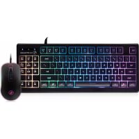
GKM600 - Keyboard IOGEAR - Free user manual and instructions
Find the device manual for free GKM600 IOGEAR in PDF.



| Brand | IOGEAR |
| Model | GKM600 |
| Product Type | Gaming keyboard with RGB mouse |
| Power | USB 2.0 (powered via port) |
| System Compatibility | Windows Vista, 7, 8, 8.1, 10 |
| Backlighting | RGB with multiple modes: rainbow wave, breathing, color rotation, custom |
| Shortcut Keys | 12 Fn+F1 to F12 keys: media, volume, mute, stop, navigation, email, internet, keyboard lock, calculator |
| Windows Key Lock | Yes, via Fn + Windows key |
| All Keys Lock | Yes, Fn + F11 |
| WASD Swap | Yes, Fn + W to swap with arrow keys |
| Anti-ghosting | 26 simultaneous keys (Tab, QWERT, ASDFG, ZXCVBM, Ctrl, Alt, Space, arrows) |
| Brightness and Speed Settings | Fn + up/down arrows for brightness, left/right for speed |
| Programming Software | Downloadable at iogear.com/support/dm/driver/GME631 |
| Compliance | FCC Class B |
| Warranty | 3-year limited |
| Package Contents | 1 RGB mouse, 1 RGB keyboard, quick start guide, warranty card |
| Cleaning and Maintenance | Unplug before cleaning, use a soft dry cloth |
Frequently Asked Questions - GKM600 IOGEAR
User questions about GKM600 IOGEAR
0 question about this device. Answer the ones you know or ask your own.
Ask a new question about this device
Download the instructions for your Keyboard in PDF format for free! Find your manual GKM600 - IOGEAR and take your electronic device back in hand. On this page are published all the documents necessary for the use of your device. GKM600 by IOGEAR.
USER MANUAL GKM600 IOGEAR
System Requirements 4
Mouse Overview 5
Keyboard Overview 6
Installation 7
Operation for Mouse 8
Operation for Keyboard 9
Compliance Information 11
Limited Warranty 12
Contact 12
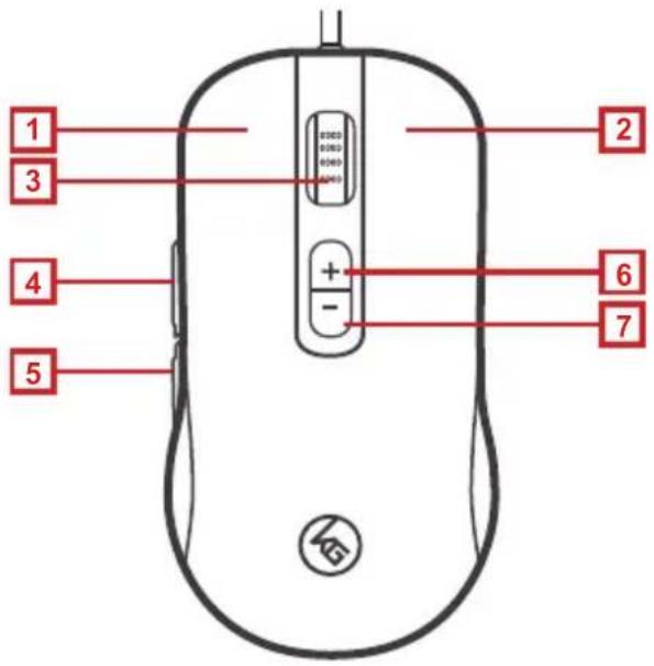
- Left button / Select
- Right button / Menu
- Scroll wheel / 3rd button
- 4th button / Forward
- 5th button / Backward
- DPI + / 6th button
- DPI - / 7th button
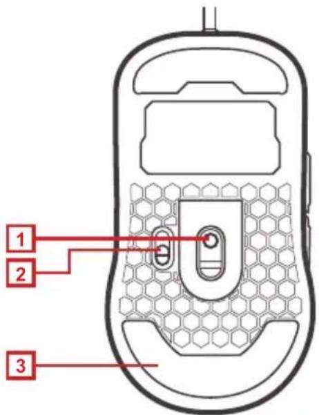
Mouse Back View
- Optical sensor
- Reporting rate switch 125/500/1000 rps
- Anti-friction base pad
Keyboard Overview
Keyboard Front view
- Windows Lock LED – turns on when Fn + ≡ is pressed
- Caps Lock LED – turns on when Caps Lock key is pressed
- Scroll Lock LED – turns on when Scroll Lock key is pressed
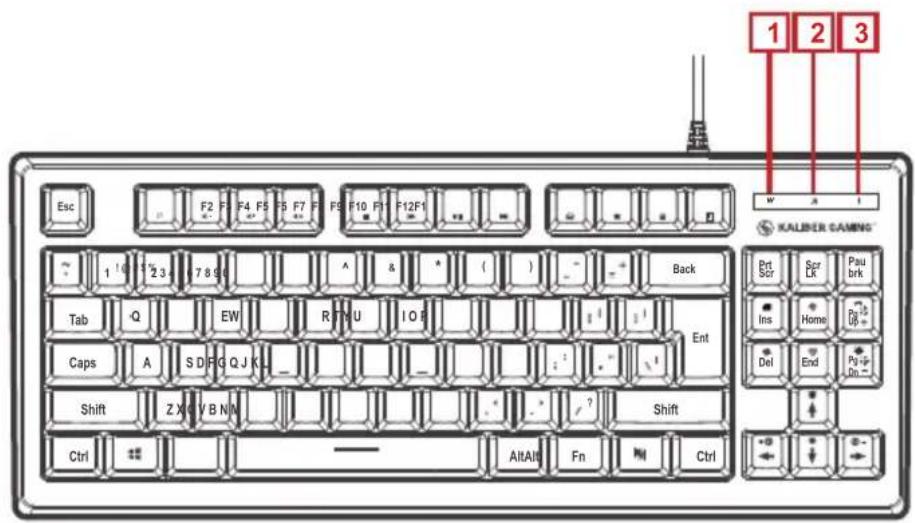
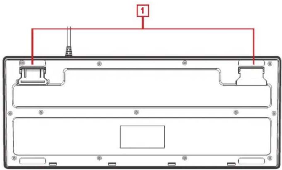
Keyboard Back view
- Foldable Legs – allow user to adjust the angle of keyboard
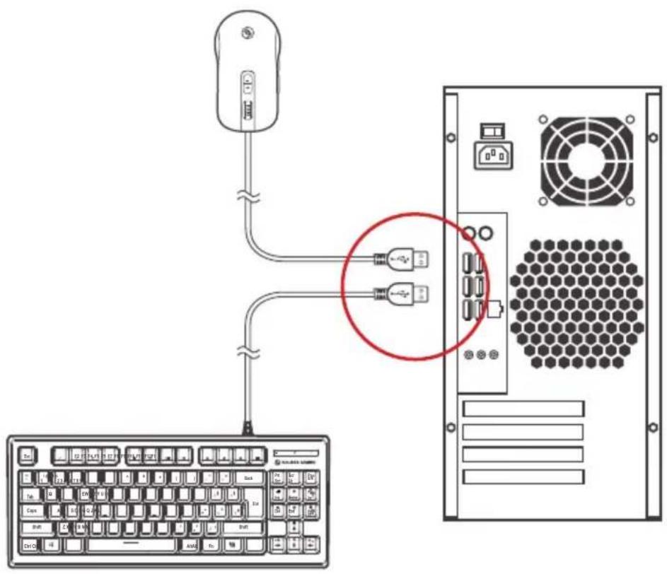
Installation
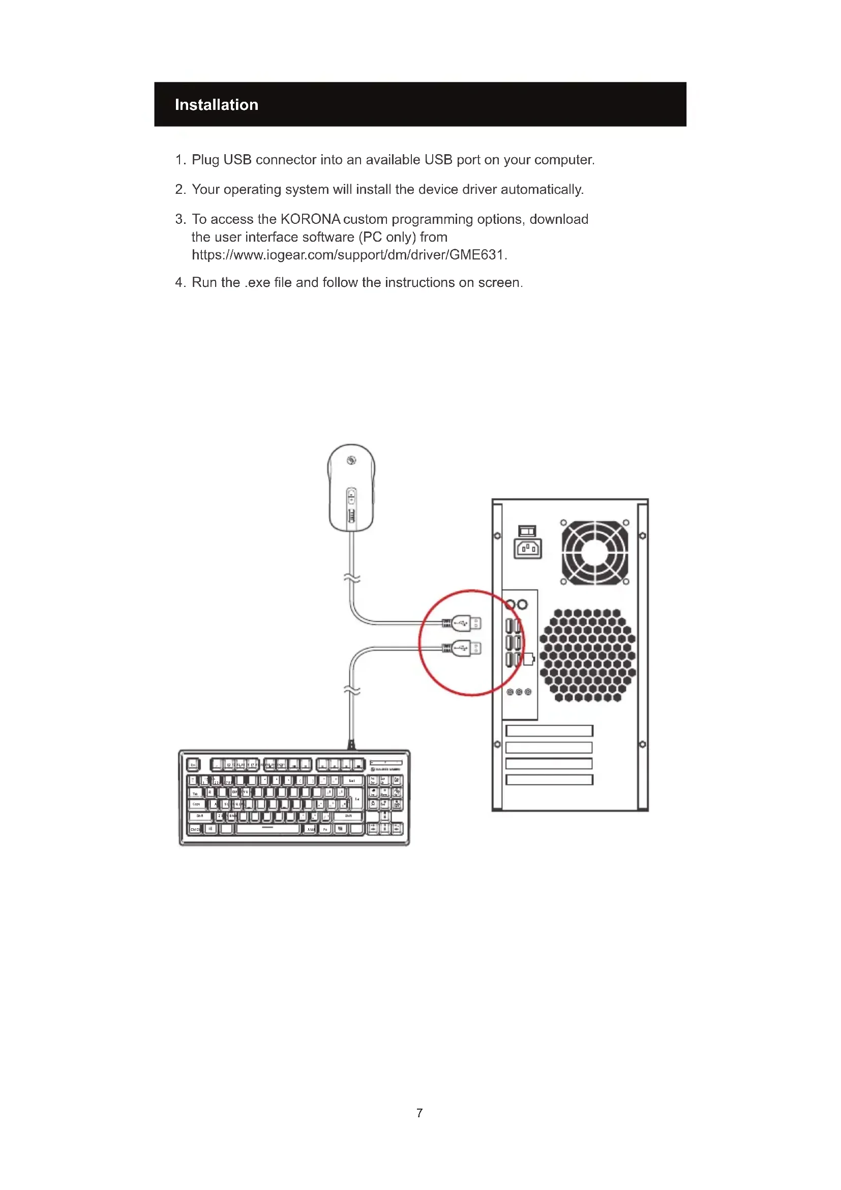
- Plug USB connector into an available USB port on your computer.
- Your operating system will install the device driver automatically.
- To access the KORONA custom programming options, download the user interface software (PC only) from https://www.iogear.com/support/dm/driver/GME631.
- Run the .exe file and follow the instructions on screen.
Operation for Mouse
DPI Setting:
The GME631's dpi buttons cycles through 5 preset resolution settings or through 5 custom settings that can be programmed with the user interface software. Press the + or - dpi button to increase or decrease to the next resolution setting. The illumination changes color to indicate the DPI has been changed.
Default DPI Resolution LED Color
| 400 Red |
| 800 Green |
| 1600 Blue |
| 3200 Yellow |
| 5000 Purple |
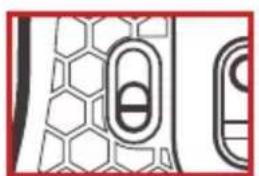
Report Rate Setting:
The GME631 features an adjustable reporting rate 125, 500 or 1000 reports per second (rps) to better tailor the mouse to your system. Theoretically speaking, the highest 1000 rps settings should be the best setting for gaming, however due to the difference between system polling rates and refresh rates, and availability of system resources, a lower setting of 500 or sometimes even 125 rps may provide improved motion smoothness with some games. Try the different settings by moving the Report Rate Switch on the bottom of the GME631, and see which works best for you.
natural_image
Pure electrical circuit lines without any symbols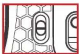
natural_image
Pure electrical circuit lines without any symbols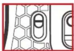
natural_image
Pure electrical circuit lines without any symbols1000 rps 500 rps 125 rps
Windows Key Lockout
The Windows key lockout prevents the Windows menu from popping up and interfering with your game if accidentally pressed while gaming. Press Fn + 📄 key to lockout the Windows menu function. The Windows Lock LED will light up to confirm the Windows key is locked out. Press Fn + 📄 again to unlock the Windows key.
All-Keys Lockout
If you take a break from gaming but wish to leave your system running, you can lock your keyboard to prevent unwanted keystrokes while away. Press Fn + 11 to lock the keys, and press Fn + 11 again to unlock.
WASD Key Swap
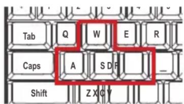
The W, A, S, and D key functions can be swapped with the arrow keys for better functionality with certain games, especially MMO (Massively Multiplayer Online) games. Press Fn + W to swap key functions, and press Fn + W again to swap back to normal operation.
Hotkeys
There are 12 hotkeys, each with two different functions depending on the keyboard mode. In Windows Mode (default) the F keys provide access to the standard window functions listed below:
| Windows Hotkeys | Function | |
| Fn + F1 | Media Player | |
| Fn + F2 | Volume Down | |
| Fn + F3 | Volume up | |
| Fn + F4 | Mute | |
| Fn + F5 | Stop | |
| Fn + F6 | Previous Track | |
| Fn + F7 | Play/Pause | |
| Fn + F8 | Next Track | |
| Fn + F9 | ||
| Fn + F10 | Web/Home | |
| Fn + F11 | All functions keys locked/unlocked | |
| Fn + F12 | Calculator | |
Anti-Ghosting Keys
Your HVER features 26 full anti-ghosting keys to ensure all your keystrokes are registered, especially during intense gaming sessions. These keys are:
Tab, Q, W, E, R, T, CapsLk, A, S, D, F, G, L Shift, Z, X, C, V, B, M, L Ctrl, L Alt, Space ,↑(UP),↓(Down),←(Left),→(Right).
RGB Backlight Functions
The RGB LED backlight has multiple lighting options. Press the Fn key plus any key noted below to customize your lighting experience.
Fn + Ins Color change
Fn + End Breathing (single color/rotate colors)
Fn + PgUp Custom lighting mode
Fn + PgDn Backlight On/Off
Custom Lighting Mode
To set the Custom Lighting Mode:
- Press Fn + PgUp to start custom programming. The 3 status LEDs will begin flashing.
- Press FN + number key 2-6 to set the color for the lighting zone you want to light. Each press will cycle the zone color as follows: Red, Blue, Green, Purple, Cyan, Yellow, White, Off.
- Press Fn + PgUp again to exit and save setting. The 3 status LEDS will stop flashing. NOTE: The Custom Lighting Mode setting is not permanently saved, so to reset the default setting, simply unplug the keyboard then reconnect.
Backlight Pattern Adjustments
Press Fn + ▲ to increase brightness
Press Fn + ▼ to decrease brightness
Press Fn + ◀ to increase light speed
Press Fn + ▶ to decrease light speed
Federal Communication Commission Interference Statement
This equipment has been tested and found to comply with the limits for a Class B digital service, pursuant to Part 15 of the FCC rules. These limits are designed to provide reasonable protection against harmful interference in a residential installation. Any changes or modifications made to this equipment may void the user's authority to operate this equipment. This equipment generates, uses, and can radiate radio frequency energy. If not installed and used in accordance with the instructions, may cause harmful interference to radio communications. However, there is no guarantee that interference will not occur in a particular installation. If this equipment does cause harmful interference to radio or television reception, which can be determined by turning the equipment off and on, the user is encouraged to try to correct the interference by one or more of the following measures:
• Reorient or relocate the receiving antenna
- Increase the separation between the equipment and receiver
- Connect the equipment into an outlet on a circuit different from that to which the receiver is connected
- Consult the dealer or an experienced radio/TV technician for help
FCC Caution: Any changes or modifications not expressly approved by the party responsible for compliance could void the user's authority to operate this equipment.
Limited Warranty
This product carries a 3 Year Limited Warranty. For the terms and conditions of this warranty, please go to https://www.iogear.com/support/warranty
Register online at https://www.iogear.com/register
Important Product Information
Product Model ____
Serial Number ____
Contact
WE'RE HERE TO HELP YOU!
NEED ASSISTANCE SETTING UP THIS PRODUCT?
Make sure you:
- Visit www.iogear.com for more product information
- Visit www.iogear.com/support for live help and product support
IOGEAR
https://iogear.custhelp.com
support@iogear.com
www.iogear.com
www.kalibergaming.com
Installation
natural_image
Abstract geometric pattern with hexagonal and oval shapes (no text or symbols)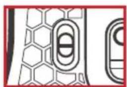
natural_image
Pure geometric pattern with hexagonal and oval shapes, no text or symbols present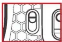
natural_image
Pure electrical circuit lines without any symbols1000 rps 500 rps 125 rps
https://iogear.custhelp.com
support@iogear.com
www.iogear.com
Instalación
natural_image
Pure electrical circuit lines without any symbols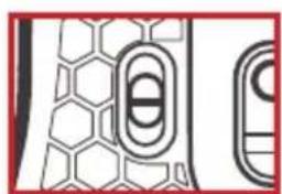
natural_image
Pure geometric pattern with hexagonal and oval shapes, no text or symbols present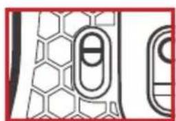
natural_image
Pure electrical circuit lines without any symbols1000 rps 500 rps 125 rps
https://iogear.custhelp.com
support@iogear.com
www.iogear.com
www.kalibergaming.com


- Mouse Back View
- Keyboard Overview
- Keyboard Front view
- Keyboard Back view
- Installation
- Operation for Mouse
- DPI Setting:
- Report Rate Setting:
- Windows Key Lockout
- All-Keys Lockout
- WASD Key Swap
- Hotkeys
- Anti-Ghosting Keys
- RGB Backlight Functions
- Custom Lighting Mode
- To set the Custom Lighting Mode:
- Backlight Pattern Adjustments
- Federal Communication Commission Interference Statement
- Limited Warranty
- Contact
- WE'RE HERE TO HELP YOU!
- NEED ASSISTANCE SETTING UP THIS PRODUCT?
- Make sure you:
- IOGEAR
- Instalación
Brand : IOGEAR
Model : GKM600
Category : Keyboard