
WVCM2000 - Surveillance Camera PANASONIC - Free user manual and instructions
Find the device manual for free WVCM2000 PANASONIC in PDF.

| Product Type | Surveillance Color Monitor |
| Brand | Panasonic |
| Model | WV-CM2000 |
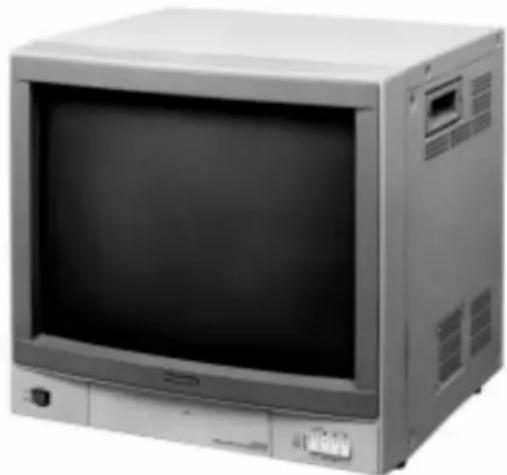
| Screen Diagonal | 54.8 cm (21 inches) |
| Actual Viewable Area | 51 cm (20-1/16 inches) diagonal |
| Resolution | 500 lines or less (measured at center) |
| Power Supply | Mains 220-240 V, 50 Hz |
| Power Consumption | Approx. 99 watts |
| Weight | 30 kg |
| Dimensions (W x H x D) | 500 x 474 x 500 mm |
| Ambient Operating Temperature | -10°C to +50°C |
| Ambient Operating Humidity | Less than 90% |
| Composite Video Input | 1.0 Vcc/75 ohms, Hi-Z loop |
| S-Video Input | Y: 1.0 Vcc/75 ohms, C: 0.3 Vcc (NTSC) or 0.286 Vcc (PAL) |
| Audio Input | -8 dB/Hi-Z |
| Speaker Output | 1.3 W |
| Compatible Video Standards | PAL, NTSC, M-NTSC |
| Main Functions | Hue, color, brightness, contrast, sharpness adjustments; image selector (NARROW/WIDE); 3.58 MHz filter; manual/remote standby |
| Maintenance and Cleaning | Clean with a soft, dry cloth. Do not use abrasive products or solvents. |
| Safety | Do not expose to rain or moisture. Do not open the housing. Unplug before cleaning. |
| Spare Parts and Repairability | Entrust all repairs to a qualified technician. Use genuine Panasonic parts. |
Frequently Asked Questions - WVCM2000 PANASONIC
User questions about WVCM2000 PANASONIC
0 question about this device. Answer the ones you know or ask your own.
Ask a new question about this device
Download the instructions for your Surveillance Camera in PDF format for free! Find your manual WVCM2000 - PANASONIC and take your electronic device back in hand. On this page are published all the documents necessary for the use of your device. WVCM2000 by PANASONIC.
USER MANUAL WVCM2000 PANASONIC
Operating Instructions
Colour Monitor
WV-CM2000
ENGLISH VERSION
We declare under our sole responsibility that the product to which this declaration relates is in conformity with the standards or other normative documents following the provisions of Directive EEC/89/336.
To ensure safe operation the three-pin plug supplied must be inserted only into a standard three-pin power point which is effectively earthed through the normal household wiring. Extension cords used with the equipment must be three-core and be correctly wired to provide connection to earth. Wrongly wired extension cords are a major cause of fatalities.
The fact that the equipment operates satisfactorily does not imply that the power point is earthed and that the installation is completely safe. For your safety, if in any doubt about the effective earthing of the power point, consult a qualified electrician.
CAUTION
RISK OF ELECTRIC SHOCK
DO NOT OPEN

CAUTION:
TO REDUCE THE RISK OF ELECTRIC SHOCK, DO NOT REMOVE COVER (OR BACK), NO USER SERVICEABLE PARTS INSIDE.
REFER SERVICING TO QUALIFIED SERVICE PERSONNEL.

The lightning flash with arrowhead symbol, within an equilateral triangle, is interned to alert the user to the presence of uninsulated "dangerous voltage" within the product's enclosure that may be of sufficient magnitude to constitute a risk of electric shock to persons.

The exclamation point within an equilateral triangle is intended to alert the user to the presence of important operating and maintenance (servicing) instructions in the literature accompanying the appliance.
The serial number of this product may be found on the bottom of the unit.
You should note the serial number of this unit in the space provided and retain this book as a permanent record of your purchase to aid identification in the event of theft.
Model No.
Serial No.
This appliance is supplied with a moulded three pin mains plug for your safety and convenience.
A 13 amp fuse is fitted in this plug.
Should the fuse need to be replaced please ensure that the replacement fuse has a rating of 13 amp and that it is approved by ASTA or BSI to BS1362
Check for the ASTA mark or the BSI mark on the body of the fuse.
If the plug contains a removable fuse cover you must ensure that it is refitted when the fuse is replaced.
If you lose the fuse cover the plug must not be used until a replacement cover is obtained.
A replacement fuse cover can be purchased from your local Panasonic Dealer.
IF THE FITTED MOULDED PLUG IS UNSUITABLE FOR THE SOCKET OUTLET IN YOUR HOME THEN THE FUSE SHOULD BE REMOVED AND THE PLUG CUT OFF AND DISPOSED OF SAFELY. THERE IS A DANGER OF SEVERE ELECTRICAL SHOCK IF THE CUT OFF PLUG IS INSERTED INTO ANY 13 AMP SOCKET.
If a new plug is to be fitted please observe the wiring code as shown below.
If in any doubt please consult a qualified electrician.
WARNING: This apparatus must be earthed.
IMPORTANT
The wires in this mains lead are coloured in accordance with the following code.
Green-and-yellow: Earth
Blue: Neutral
Brown: Live
As the colours of the wire in the mains lead of this appliance may not correspond with the coloured markings identifying the terminals in your plug, proceed as follows.
The wire which is coloured green-and-yellow must be connected to the terminal in the plug which is marked with the letter E or by the earth symbol ±± or coloured green or green-and-yellow.
The wire which is coloured blue must be connected to the terminal in the plug which is marked with the letter N or coloured black.
The wire which is coloured brown must be connected to the terminal in the plug which is marked with the letter L or coloured red.
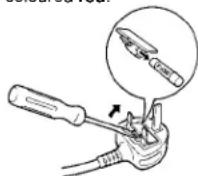
How to replace the fuse
Open the fuse compartment with
a screwdriver and replace the fuse and fuse cover.
CONTENTS
PREFACE 1
FEATURES 1
PRECAUTIONS 1
MAJOR OPERATING CONTROLS AND
THEIR FUNCTIONS 2
CABLEINFORMATIONS 5
SYSTEM CONNECTIONS 6
APPEARANCE 7
SPECIFICATIONS 8
PREFACE
The Panasonic's Colour Monitor WV-CM2000 has a high resolution S-VIDEO INPUT to ensure high definition picture quality for a PAL/NTSC/M-NTSC (Modeified NTSC) signal. All controls except for power and Input Signal Selection Switch are covered by a push door to give a sleek appearance on the front. The master controls for Tint, Colour, Brightness and Contrast are provided with sub controls to permit adjustment of preset levels.
Standard BNC and S-Video input and output connectors enabled WV-CM2000 to be used with other CCTV monitors or Panasonic video tape recorder.
FEATURES
Approx. 54.8 cm (21" diagonal)
- Switchable of AFC time constant
- Looping through BNC connectors for video input and output
- Looping through S-video connectors for S-video input and output.
- Looping through RCA pin jack for audio input and output
PRECAUTIONS
- Do not block the ventilation slots.
- Do place the video monitor at least 5cm (2") apart from the wall.
- Do not expose the monitor to water or moisture.
- Do not operate the monitor if it becomes wet.
- Do take immediate action if ever the monitor does become wet. Turn power off and refer service personnel. Moisture can damage the monitor and also create the danger of electric shock.
- Do not drop metallic parts through slots. This action could permanently damage the monitor. Do turn power off immediately and refer servicing to qualified service personnel.
- Do not attempt to disassemble the monitor. To prevent electric shock, do not remove screws or cover. There are no user serviceable parts inside. Refer servicing to qualified service personnel.
PAL/NTSC/M-NTSC selectable
3.58 MHz Trap On/Off Switch for NTSC
- Stand-by On/Off Switch is provided for energy saving
- Picture Selection Switch is provided.
Max. 1.3W for speaker output
- Selectable of 1-4 channel for input and output signal.
- Do not use the monitor beyond its temperature, humidity or power source ratings.
(a) Ambient temperature must not range beyond -10^ + 50^ .
(b) Avoid using the monitor when humidity is above 90% .
(c) The input power must be 220-240 VAC at 50Hz .
MAJOR OPERATING CONTROLS AND THEIR FUNCTIONS
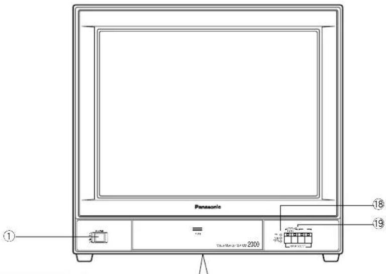
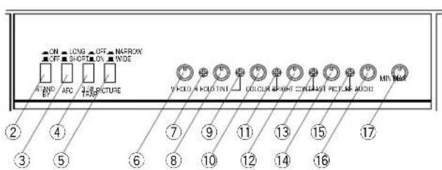
1. Power Switch (POWER ON/OFF)
This is a push-push type switch which turns the power of the monitor on and off.
Press once and the switch remains down ( ) for turning on the power of monitor.
Press again, the switch comes up (■) for turning off the power of the monitor.
2. Stand-by On/Off Switch (STAND BY ON/OFF)
This is a push-push type switch which turns on/off this switch.
Press once and the switch remains down ( ) for turning on this switch.
Press again, the switch comes up (■) for turning off this switch.
When selecting the Standby On/Off mode by using the external signal, set this switch to the ON position.
3. AFC time Selection Switch (AFC, LONG/SHORT)
This is a push-push type switch which selects the AFC time. Press once, then the switch remains down ( - ) for selecting the LONG position.
Press again, then the switch comes up (■) for selecting the SHORT position.
Normally (standard video signal), set this switch to the SHORT position.
When the video signal is jittery, set this switch to the LONG position.
4.3.58 MHz Trap Filter On/Off Switch (3.58 TRAP, ON/OFF)
This is a push-push type switch which turns on/off the 3.58 MHz Trap Filter.
Press once, then the switch remains down ( ) for tuning off the 3.58 MHz Trap Filter.
Press again, then the switch remains down (■) for turning on the 3.58 MHz Trap Filter function.
Note: When decreasing the colour dots noise on the monitor screen, turn on this switch.
5. Picture Selection Switch (PICTURE NARROW/WIDE)
NARROW: Select this position when the video source is come from the high resolution camera or the like.
WIDE: Select this position when the video source is come from the low resolution VTR.
6. Vertical Hold Control (V-HOLD)
This control is used to adjust the picture in vertically.
7. Horizontal Hold Control (H-HOLD)
This control is used to lock the picture in horizontally.
8. Tint Control (TINT)
Turn this control clockwise for purplish colour of the picture and turn this counterclockwise for greenish colour of the picture.
9. Tint Subcontrol
10. Colour Control (COLOUR)
Turn this control clockwise to increase the picture colour and turn this control counterclockwise to decrease the picture colour.
11. Colour Subcontrol
12. Bright Control (BRIGHT)
Turn this control clockwise to increase the picture brightness and turn this control counterclockwise to decrease the picture brightness.
13. Bright Subcontrol
14. Contrast Control (CONTRAST)
Turn this control clockwise to increase the picture contrast and turn this control counterclockwise to decrease the picture contrast.
15. Contrast Subcontrol
16. Picture Adjustment (PICTURE)
Turn this control clockwise for sharp picture and turn this control counterclockwise for soft picture.
17. Audio Volume (AUDIO, MIN/MAX)
Turn this volume clockwise to increase the audio level and turn this volume counterclockwise to decrease the audio level.
18. Power Indicator/Broadcast System Indicator (PAL, NTSC, M-NTSC)
When turning on the power of this monitor without any input signals, PAL LED indicator lights in red.
The NTSC LED indicator lights in green with the NTSC input signal.
The M-NTSC LED indicator light in orange with the M-NTSC input signal.
These indicators are switched by the difference in the broadcasting system connected to this monitor.
In the Stand-by mode, PAL and NTSC LEDs light together.
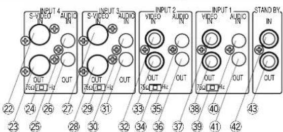
19. Input Signal Selection Switches (INPUT 1/2/3/4)
By pressing the desired switch, both Video (S-Video) and Audio input signals are selected.
Note : The video and audio input signal selected once will be kept even if the power of this monitor is turned off.
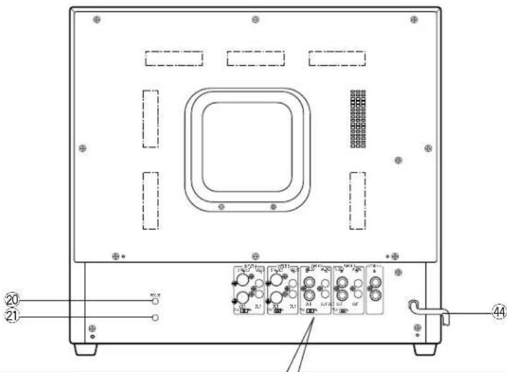
20. Focus Control (FOCUS)
21. Screen Control
This control is preset at the factory.
Do not adjust this control.
When the adjustment of this control is required, refer to the qualified service personnel.
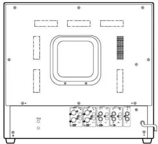
22. S-Video Input Connector (INPUT 4, S-VIDEO IN)
This connector accepts a S-Video (PAL/NTSC) signal.
23. S-Video Output Connector (INPUT 4, S-VIDEO OUT)
The S-Video input signal connected to the S-Video Input Connector (22) is looped through to this connector.
24. S-Video Termination Switch (INPUT 4, 75 /H_i - z
When bridging or looping through the S-Video signal, set this switch to Hi-z position, and other cases this switch should be set to 75 position.
25. Audio Input Connector (INPUT 4, AUDIO IN)
-8 dB/Hi-z audio signal can be supplied to this input connector.
26. Audio Output Connector (INPUT 4, AUDIO OUT)
The audio input signal connected to the Audio Input Connector (25) is looped through to this connector.
27. S-Video Input Connector (INPUT 3, S-VIDEO IN)
This connector accepts a S-Video (PAL/NTSC) signal.
28. S-Video Output Connector (INPUT 3, S-VIDEO OUT)
The S-Video input signal connected to the S-Video Input Connector (27) is looped through to this connector.
29. S-Video Termination Switch (INPUT 3, 75 / Hi-z )
When bridging or looping through the video signal, set this switch to Hi-z position, and other cases this switch should be set to 75 position.
30. Audio Input Connector (INPUT 3, AUDIO IN)
-8 dB/Hi-z audio signal can be supplied to this input connector.
31. Audio Output Connector (INPUT 3, AUDIO OUT)
The audio input signal connected to the Audio Input Connector (30) is looped through to this connector.
32. Video Input Connector (INPUT 2,VIDEO IN)
This connector accepts a composite PAL/NTSC/M-NTSC video signal.
33. Video Output Connector (INPUT 2,VIDEO OUT)
The video input signal connected to the Video Input Connector (32) is looped through to this connector.
34. Video Termination Switch (INPUT 2, 75 / Hi-z )
When bridging or looping through the video signal, set this switch to Hi-z position, and other cases this switch should be set to 75 position.
35. Audio Input Connector (INPUT 2, AUDIO IN)
-8 dB/Hi-z audio signal can be supplied to this input connector.
36. Audio Output Connector (INPUT 2, AUDIO OUT)
The audio input signal connected to the Audio Input Connector (35) is looped through to this connector.
37. Video Input Connector (INPUT 1,VIDEO IN)
This connector accepts a composite PAL/NTSC/M-NTSC video signal.
38. Video Output Connector (INPUT 1,VIDEO OUT)
The video input signal connected to the Video Input Connector (37) is looped through to this connector.
39. Video Termination Switch (INPUT 1, 75 / Hi-z )
When bridging or looping through the video signal, set this switch to Hi-z position, and other cases this switch should be set to 75 position.
40. Audio Input Connector (INPUT 1, AUDIO IN)
-8 dB/Hi-z audio signal can be supplied to this input connector.
41. Audio Output Connector (INPUT 1, AUDIO OUT)
The audio input signal connected to the Audio Input Connector (40) is looped through to this connector.
42. Standby Input Connector (STAND BY IN)
Supply the control signal to select the Standby On/Off mode to this connector.
Only when setting the Stand-by On/Off Switch to the ON position, this control signal can be functioned.
When the coaxial cable from this connector is grounded, the picture is appeared on the screen.
43. Standby Output Connector (STAND BY OUT)
This connector is looped through to the Standby Input Connector(42).
44. Power Cord
CAUTION: The supplied power cord is designed for use on the supplied 220-240V AC supply only.
CABLE INFORMATIONS
Power Cord
- Keep the Power Switch (1) in the OFF position during installation.
- Connect the Power Cord to a grounded electrical outlet.
Video Cable
- Use 75-ohm coaxial cable [RG-59/U (3C-2V), RG-6/U (5C-2V), RG-14/U (7C-2V), RG-15/U (10C-2V)]
-
Up to 10 monitors can be hooked up in this configuration before signal loss occurs. Total cable length should not exceed 150m .
-
Wiring Precautions :
-
Do not bend coaxial cable into a curve whose radius is smaller than 10 times of its diameter.
- Never crush or pinch the cable.
All these will change the impedance of the cable and cause poor picture quality.
| Type of RG-59/U RG-6U coaxial cable (3C-2V) (5C-2V) RG-11/U RG-15/U (7C-2V) (10C-2V) | |||||
| Recommended (ft) maximum cable length (m) 2 | 825 | 1,650 | 1,980 | 2,640 | |
| 50 | 500 | 600 | 800 | ||
SYSTEM CONNECTIONS
1. Single Monitor Connection
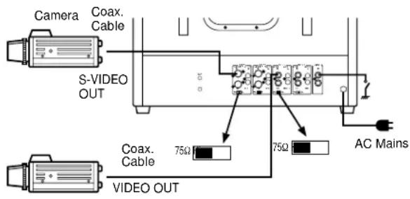
- Connect the coaxial cable between the S-Video Output connector of the camera or VTR and the S-Video Input Connector (22) or (27) of this monitor.
- Connect the coaxial cable between the Video Output Connector of the camera or VTR and the Video Input Connector (32) or (37) of this monitor.
- Set the S-Video Termination Switch (24) or (29) to 75Ω position.
- Set the Video Termination Switch (34) or (39) to 75 position.
- Connect the coaxial cable to the Standby Input Connector (42) when the Standby On/Off mode is selected by the external signal.
2. Multiple Monitor Connection

- Connect the coaxial cable between the S-Video or Video Output terminal of the camera or VTR and the S-Video or Video Input Connector (22), (27), (32) or (37) of this monitor.
-
Connect the coaxial cable between the S-Video/Video Output Connector (23), (28), (33) or (38) on the first monitor and the S-Video/Video Input Connector (22), (27), (32) or (37) on the second monitor, and continue until all monitors are connected.
-
Set the S-Video/Video Termination Switch (24), (29), (34) or (39) of the first and intermediate monitors to Hi-Z position. Then set the S-Video/Video Termination Switch (24), (29), (34) or (39) of the last monitor to 75 position.
- Connect the coaxial cable to the Standby Input Connector (42) when the Standby On/Off mode is selected by the external signal.
- Connect the coaxial cable between the Standby Output Connector (43) on the first monitor and the Standby Input Connector (42) on the second monitor, and continue until all monitors are connected.
3. Audio Circuit Signal
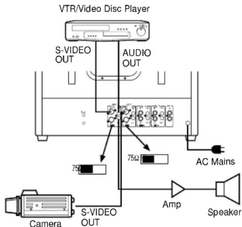
- Connect the coaxial cable between the Video or S-Video Output connector of VTR or camera and the S-Video/Video Input Connector (22), (27), (32) or (37) on this monitor.
- Connect the audio cable between the Audio Output Connector of VTR and the Audio Input Connector (25), (30), (35) or (40) of this monitor, and connect the audio cable between the Audio Input Terminal of audio amplifier to the Audio Output Connector (26), (31), (36) or (41) of this monitor.
- Set the S-Video/Video Termination Switch (24), (29), (34), or (39) to 75 position.
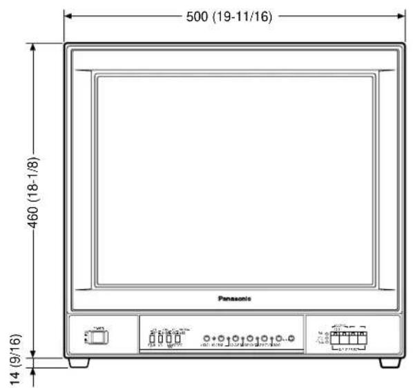
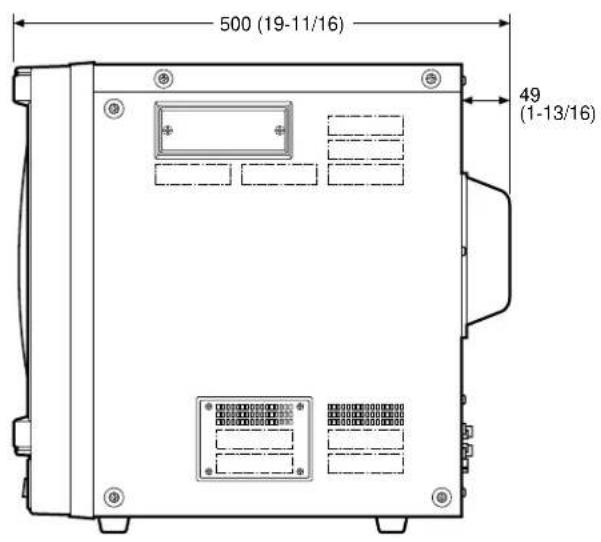
APPEARANCE
Unit: mm (inches)
SPECIFICATIONS
Power Source: WV-CM2000/A, WV-CM2000/B, WV-CM2000/G: 220 - 240V AC 50Hz
Power Consumption: Approx. 99 watts
Video Input/Output : 1.0 Vp-p composite/75 ohms or Hi-z looping through
S-Video Input/Output : Y : 1.0 Vp-p/75 ohms or Hi-z looping through (PAL/NTSC)
C:0.3 Vp-p 75 ohms or Hi-z looping through (PAL)
C:0.286 Vp-p 75-ohms Hi-z looping through (NTSC)
Scanning Size: Approx. 8%
CRT Size: 54.8 cm (21" diagonal)
Actual Visual Size: 51 cm (20-1/16" diagonal)
Audio Input/Output: -8dB/Hi-z
Speaker Output : 1.3 watts
Resolution : 500 lines or more (at centre)
Sweep Linearity : Horizontal : 5% or less
Vertical: 5% or less
Sweep Giometory : 2% or less
Stand-by: Manual/External control
AFC Speed : Short/Long switchable
3.58 MHz Trap: On/Off switchable
Picture Selection : Narrow/Wide switchable
Ambient Operating Temperature :
-10^ + 50^(14^ - 122^)
Ambient Operating Humidity :
Less than 90%
Dimensions :
Weight and dimensions shown are approximate.
Specifications are subject to change without notice.
DEUTSCHE AUSGABE
(GERMAN VERSION)
INHALT
VORWORT 10
MERKMALE 10
(PICTURE NARROW/WIDE)
Matsushita Electric Industrial Co., Ltd.
Central P.O.Box 288, Osaka 530-91, Japan
N0594-3125 YWV8QA3284DN Printed in Japan
- Operating Instructions
- ENGLISH VERSION
- CAUTION
- CAUTION:
- IF THE FITTED MOULDED PLUG IS UNSUITABLE FOR THE SOCKET OUTLET IN YOUR HOME THEN THE FUSE SHOULD BE REMOVED AND THE PLUG CUT OFF AND DISPOSED OF SAFELY. THERE IS A DANGER OF SEVERE ELECTRICAL SHOCK IF THE CUT OFF PLUG IS INSERTED INTO ANY 13 AMP SOCKET.
- IMPORTANT
- How to replace the fuse
- CONTENTS
- PREFACE
- FEATURES
- PRECAUTIONS
- MAJOR OPERATING CONTROLS AND THEIR FUNCTIONS
- Power Switch (POWER ON/OFF)
- Stand-by On/Off Switch (STAND BY ON/OFF)
- AFC time Selection Switch (AFC, LONG/SHORT)
- MHz Trap Filter On/Off Switch (3.58 TRAP, ON/OFF)
- Picture Selection Switch (PICTURE NARROW/WIDE)
- Vertical Hold Control (V-HOLD)
- Horizontal Hold Control (H-HOLD)
- Tint Control (TINT)
- Tint Subcontrol
- Colour Control (COLOUR)
- Colour Subcontrol
- Bright Control (BRIGHT)
- Bright Subcontrol
- Contrast Control (CONTRAST)
- Contrast Subcontrol
- Picture Adjustment (PICTURE)
- Audio Volume (AUDIO, MIN/MAX)
- Power Indicator/Broadcast System Indicator (PAL, NTSC, M-NTSC)
- Input Signal Selection Switches (INPUT 1/2/3/4)
- Focus Control (FOCUS)
- Screen Control
- S-Video Input Connector (INPUT 4, S-VIDEO IN)
- S-Video Output Connector (INPUT 4, S-VIDEO OUT)
- S-Video Termination Switch (INPUT 4, 75 /H_i - z
- Audio Input Connector (INPUT 4, AUDIO IN)
- Audio Output Connector (INPUT 4, AUDIO OUT)
- S-Video Input Connector (INPUT 3, S-VIDEO IN)
- S-Video Output Connector (INPUT 3, S-VIDEO OUT)
- S-Video Termination Switch (INPUT 3, 75 / Hi-z )
- Audio Input Connector (INPUT 3, AUDIO IN)
- Audio Output Connector (INPUT 3, AUDIO OUT)
- Video Input Connector (INPUT 2,VIDEO IN)
- Video Output Connector (INPUT 2,VIDEO OUT)
- Video Termination Switch (INPUT 2, 75 / Hi-z )
- Audio Input Connector (INPUT 2, AUDIO IN)
- Audio Output Connector (INPUT 2, AUDIO OUT)
- Video Input Connector (INPUT 1,VIDEO IN)
- Video Output Connector (INPUT 1,VIDEO OUT)
- Video Termination Switch (INPUT 1, 75 / Hi-z )
- Audio Input Connector (INPUT 1, AUDIO IN)
- Audio Output Connector (INPUT 1, AUDIO OUT)
- Standby Input Connector (STAND BY IN)
- Standby Output Connector (STAND BY OUT)
- Power Cord
- CABLE INFORMATIONS
- Power Cord
- Video Cable
- SYSTEM CONNECTIONS
- Single Monitor Connection
- Multiple Monitor Connection
- Audio Circuit Signal
- APPEARANCE
- SPECIFICATIONS
- DEUTSCHE AUSGABE
- (GERMAN VERSION)
- INHALT
- (PICTURE NARROW/WIDE)
Brand : PANASONIC
Model : WVCM2000
Category : Surveillance Camera