
CQR221U - Car stereo PANASONIC - Free user manual and instructions
Find the device manual for free CQR221U PANASONIC in PDF.
User questions about CQR221U PANASONIC
0 question about this device. Answer the ones you know or ask your own.
Ask a new question about this device
Download the instructions for your Car stereo in PDF format for free! Find your manual CQR221U - PANASONIC and take your electronic device back in hand. On this page are published all the documents necessary for the use of your device. CQR221U by PANASONIC.
USER MANUAL CQR221U PANASONIC
Radio Frequency Interference Statement (Part 15 of the FCC-Rules):
Applies only in U.S.A.
This equipment has been tested and found to comply with the limits for a Class B digital, pursuant to Part 15 of the FCC Rules.
- These limits are designed to provide reasonable protection against harmful interference in an automobile installation. This equipment generates, uses, and can radiate radio frequency energy and, if not installed and used in accordance with the instructions may cause harmful interference to radio communications. However, there is no guarantee that interference will not occur in a particular installation. If this equipment does cause harmful interference to radio or television reception, which can be determined by tuning the equipment off and on, the user is encouraged to consult the dealer or an experience radio technician for help.
FCC Warning:
Any unauthorized changes or modifications to this equipment would void the user's authority to operate this device.
This device complies with Part 15 of the FCC Rules.
Operation is subject to the following two conditions.
(1) This device may not cause harmful interference, and
(2) This device must accept any interference received including interference that may cause undesired operation.
For Canada:
This Class B digital apparatus complies with Canadian ICES-003.
WARNING:
TO REDUCE THE RISK OF FIRE OR ELECTRIC SHOCK, DO NOT EXPOSE THIS PRODUCT TO RAIN OR MOISTURE.
TO REDUCE THE RISK OF FIRE OR ELECTRIC SHOCK, AND ANNOYING INTERFERENCE, USE ONLY THE INCLUDED COMPONENTS.
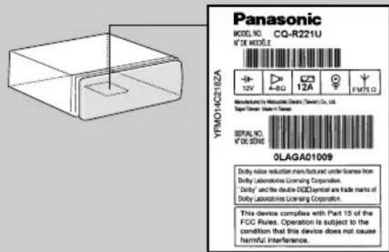
Identification Label
Find the model number and serial number on either the back or bottom of the unit. Please record them in the space below and retain this booklet as a permanent record of your purchase to help with identificaton in case of theft.
MODEL NUMBER CQ-R221U
SERIAL NUMBER
DATE PURCHASED
FROM
Panasonic welcomes you to our ever growing family of electronic product owners. We know that this product will bring you many hours of enjoyment. Our reputation is built on precise electronic and mechanical engineering, manufactured with carefully selected components and assembled by people who take pride in their work. Once you discover the quality, reliability, and value we have built into this product, you too will be proud to be a member of our family.
Use This Product Safely
When Driving
Keep the volume level low enough to be aware of road and traffic conditions.
When Car Washing
Do not expose the product, including the speakers and tapes, to water or excessive moisture. This could cause electrical shorts, fire, or other damage.
When Parked
Parking in direct sunlight can produce very high temperatures inside your vehicle. Give the interior a chance to cool down before switching the unit on.
Use the Proper Power Supply
This product is designed to operate of a 12 VDC, negative ground battery system (the normal system in a North American car.)
Protect the Tape Mechanism
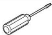
Keep magnets, screwdrivers, or other metallic objects away from the tape mechanism and tape head to prevent poor performance or malfunctions.
Use Authorized Servicenters
Do not attempt to disassemble or adjust this precision product. Please refer to the Servicenter list included with this product for service assistance.
Contents
Radio Frequency Interference Statement (Part 15 of the FCC Rules). 2
Use This product Safely. 4
□Power and Sound Controls 10 How to adjust the volume, Mute, balance, and tone for best listening
□Radio Basics. 12
Manual and automatic tuning, band selection, preset stations
□Cassette Tape Player Basics. 14 How to load, wind, play, and eject a cassette tape
□CD Changer Basics. 17
Play, repeat, random and scan, error messages
Note:
CD changer controls are applicable to units with optional CD changer
unit (sold separately).
□Clock Basics. 19 Setting the time, selecting the clock display
Remote Control Unit Preparation 20 Battery Installation
□ Installation Guide. 21 Step-by-step procedures, anti-theft system, electrical connections
Troubleshooting 29 Troubleshooting tips, where to get service help
Specifications 30


8:00


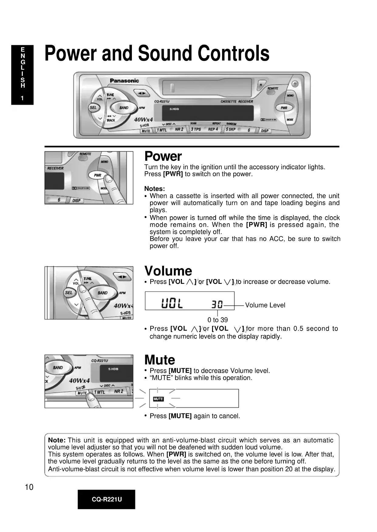
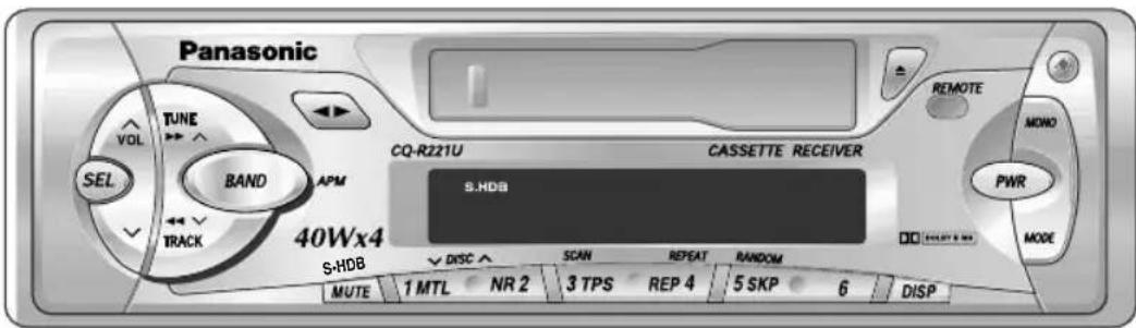
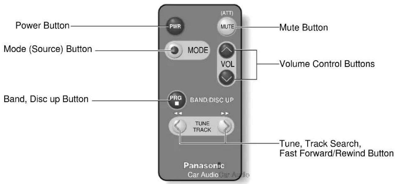
Power and Sound Controls

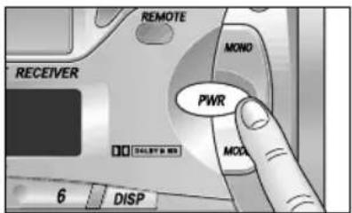
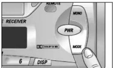
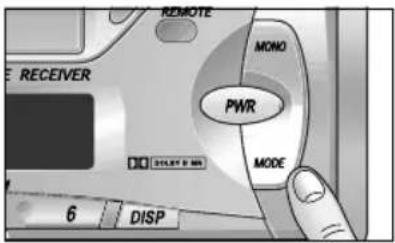
Power
Turn the key in the ignition until the accessory indicator lights. Press [PWR] to switch on the power.
Notes:
- When a cassette is inserted with all power connected, the unit power will automatically turn on and tape loading begins and plays.
- When power is turned off while the time is displayed, the clock mode remains on. When the [PWR] is pressed again, the system is completely off.
- Before you leave your car that has no ACC, be sure to switch power off.
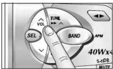
Volume
- Press [VOL ∧] or [VOL ∨] to increase or decrease volume.

- Press [VOL ∧] or [VOL ∨] for more than 0.5 second to change numeric levels on the display rapidly.
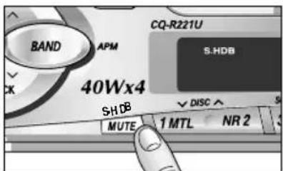
Mute
- Press [MUTE] to decrease Volume level.
- "MUTE" blinks while this operation.
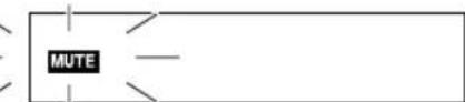
- Press [MUTE] again to cancel.
Note: This unit is equipped with an anti-volume-blast circuit which serves as an automatic volume level adjuster so that you will not be deafened with sudden loud volume.
This system operates as follows. When [PWR] is switched on, the volume level is low. After that, the volume level gradually returns to the level as the same as the one before turning off.
Anti-volume-blast circuit is not effective when volume level is lower than position 20 at the display.
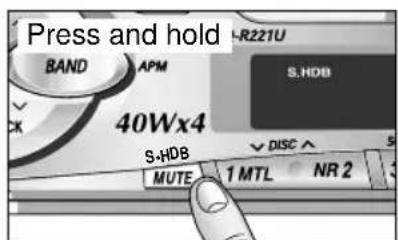
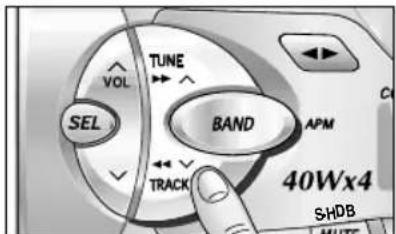
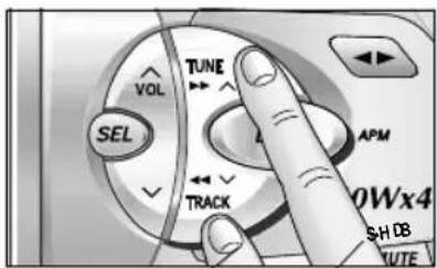
S·HDB (Super High Definition Bass)
Especially for rock music, the bass-sound will be more powerful
- Press and hold [MUTE] (S·HDB) for more than 2 seconds to be able to listen to super high-definition bass.
S·HDB
- Press and hold [MUTE] (S·HDB) for more than 2 seconds again to return to the normal tone.
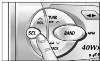
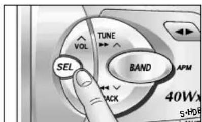
Changing Audio Modes
Press [SEL] to switch the audio mode as follows.
VOL BAS TRE
(Volume) (Bass) (Treble)
↑ BAL
FAd Fader (Balance)
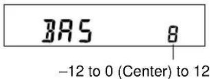
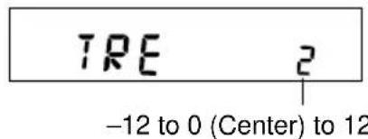
Bass and Treble
Press [SEL] to select the BASS (TREBLE) mode. Press [VOL ] or [VOL ] to increase or decrease the bass/treble response.
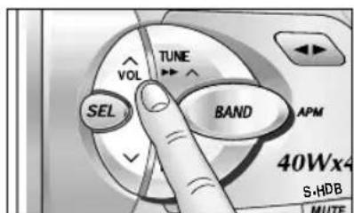
Balance
Press [SEL] to select the BALANCE mode. Press [VOL ] or [VOL ] to shift the sound volume to the right or left speakers.
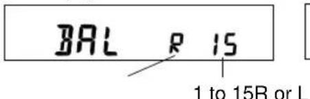
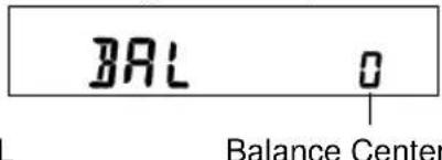
(R:Right,L:Left)
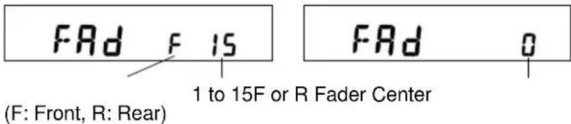
Fader
Press [SEL] to select the FADER mode. Press [VOL ∧] or [VOL ∨] to shift the sound volume to the front or rear speakers.
Note: When a control mode (BAS/TRE/BAL/FAd) is selected but no operation is made within 5 seconds (2 seconds at volume mode), the display will return to the normal operation (Radio, Cassette, etc) mode. In such a case, press [SEL] again to select the next control mode.
Radio Basics
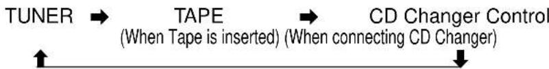
Change to the tuner mode
Press [MODE] to switch the operation mode as follows.
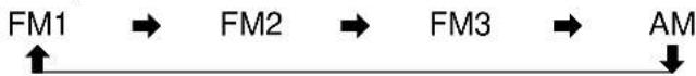
Selecting a Band
Press [BAND] to select the bands as follows.
"ST" indicator lights if the station is broadcasting in stereo.

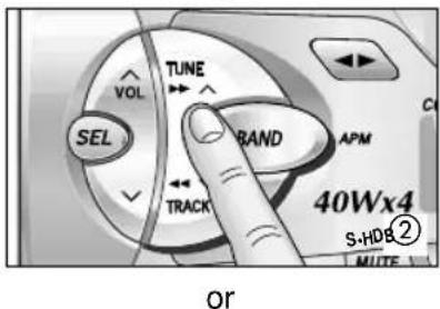
Manual Tuning
Press [TUNE ] or [TUNE ] to move to a higher or lower frequency.
Seek Tuning
Press and hold [TUNE ] or [TUNE ] for more than 0.5 seconds, then release. The radio automatically stops on the next station.
Preset Station Setting
Up to 24 stations can be preset in the station memory as follows;
| FM1 FM2 FM3 AM | ||
| 6 stations 6 stations 6 stations 6 stations | ||
Caution: For safety reasons, do not attempt to program while driving.
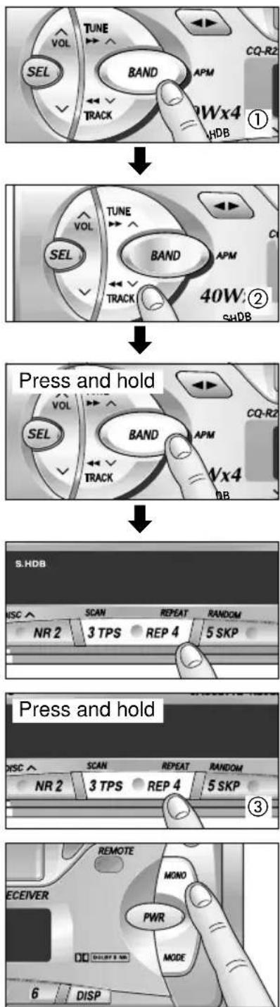
Manual Station Preset
① Press [BAND] to select a desired band.
② Use manual or seek tuning to find a station that you want to program into memory.
③ Press and hold one of the station selector buttons 1 through 6 until the display blinks. The memory is now set for that button on the band you have selected. Repeat the process to set other stations for the FM1 to AM bands.

Note: You can change the memory setting by repeating the above procedure.
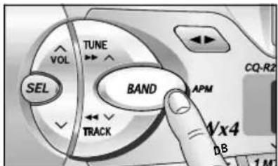
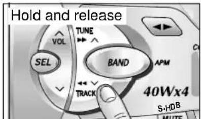
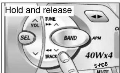
Auto Preset Memory
Select a band, and press and hold [BAND] (APM) for more than 2 seconds.
- The 6 strongest available stations will be automatically set in memory on preset buttons 1 through 6.
- Once set, the preset stations are sequentially scanned for 5 seconds.
- Press the appropriate preset button for the station you want to hear.
Note: The stations manually preset on the selected band will be deleted.
Tuning in a Preset Station
Press any of the buttons [1] through [6] to tune in the station preset by the above steps ① to ③.
To reduce interference during FM broadcasts (MONO)
Press [MONO] for monaural reception in case a lot of interference is present in an FM stereo signal or to improve the listening quality of weak FM broadcasts. To turn it off, press [MONO] again.
MONO 102.7 FM24
Cassette Tape Player Basics
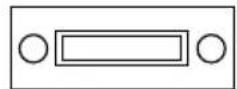
Exposed Tape Side
Loading a Cassette
Insert the cassette with the exposed tape side facing to the right. Gently push the cassette in until the loading begins. The cassette will be loaded in place and playback starts.
TAPPEU.U
Program Indicator
(This indication "rotates.)
Fast Forward
Rewind
Rewind and Fast Forward
Press either [←] to rewind or [▶] to fast forward the tape.
TRAPE
To stop rewind or fast forward, press [▶].
If you rewind the tape fully, it will play on the same program side again.
If you fast forward to the end, play will resume from the beginning of the other side of the tape.

Changing Sides
Press [▶] to switch to the program on the other side of the tape. The display changes to indicate which program is playing.
TAPETU.U
TAPE
Top Side Playing Bottom Side Playing
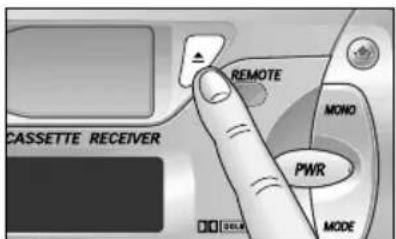
Ejecting the Tape
Press [▲] and the cassette will eject for removal, and the previous mode of operation will be resumed.
Notes:
- If power is switched off before [] is pressed, the cassette will not eject. Switch on the power again and press [] to eject the cassette.
- The cassette tape should always be removed from the cassette slot when not in use.
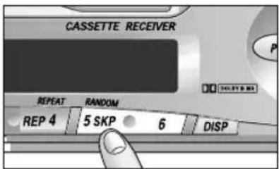
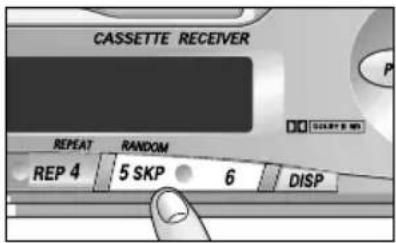
Blank Skip
Press [5] (SKP) to skip long unrecorded portions on the tape.

This is most convenient if you quickly want to skip the remaining unrecorded portions at the end of the tape and fast forward to the beginning of the first music on the reverse side of the tape.
To turn it off, press [5] (SKP) again.
Notes:
- "B-SKIP" indicator lights. However, the blank skip operation will not work if REPEAT is on. The repeat function has priority over that of the blank skip function.
- Also the blank skip operation will not work when the unrecorded portion of the tape is less than 15 seconds.
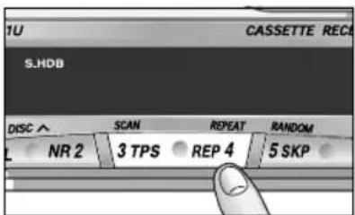
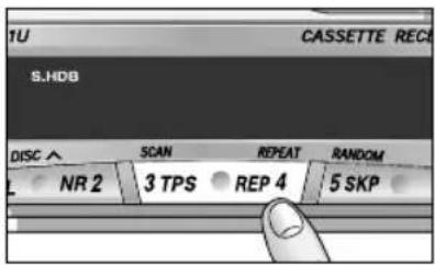
Repeat Play
Press [4] (REP) to repeat the same music you are now listening to.

After finishing the music just listened to, the rewind starts automatically until the beginning of music, and the same music starts playing again.
To turn it off, press [4] (REP) again.
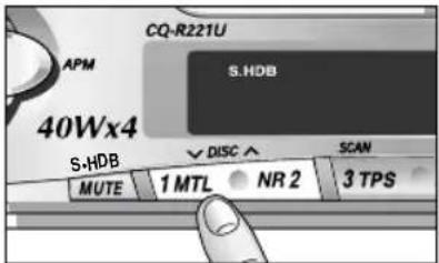
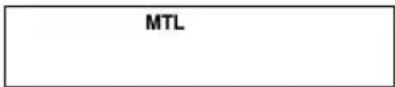
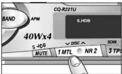
Metal Tape Mode
Press [1] (MTL) when playing metal or chromium dioxide (CrO_2) tapes.
To turn it off, press [1] (MTL) again.
Note: Playing non-metal tapes in metal tape mode mode causes high frequency imbalance, which affects tone quality.
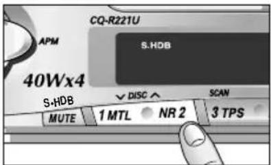
Dolby Noise Reduction
Press [2] (NR) to set the Dolby B NR mode.

To cancel the Dolby NR mode, press [2] (NR) again.
Note:
Set the Dolby B NR mode when playing back a tape recorded with Dolby B Noise Reduction.
Cassette Tape Player Basics continued


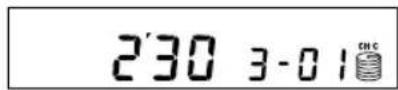
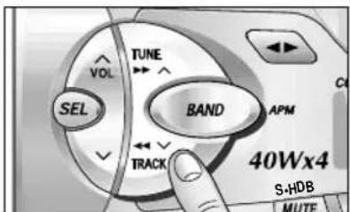
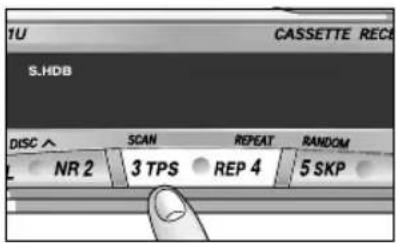
TPS Operation (Tape Program Search)
① Press [3] (TPS) to activate the tape program search mode.

② From the current selection, decide which program you want to select. Now, press [▶] several times forward (up to 9 programs) or press [←] several times backward (up to 8) to select the corresponding program number.

EX1. To select the current program again press [3] (TPS), and press [4] once.
EX2. To select the 1st program backward of the current selection, press [3] (TPS) once, and press [▲] two times.
EX3. To select the next program, press [3] (TPS) and press [▶] once.
EX4. To select the 3rd program forward of the current selection, press [3] (TPS) once, and press [ ] three times.
③ To turn it off, press [3] (TPS) again.
TAPPE
Tapeu.u1
Tapeu.u1
Tape
Note:
The TPS mode may not work correctly in the following cases. This, however, does not mean that the unit is defective.
There is an interval less than 4 seconds or having a high level of noise or hum between programs.
There is particularly low-level passage during the program.
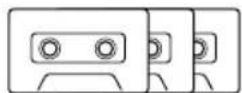
Notes on Cassette Tapes
Tape Slack: Use a pencil or similar object to take up the slack as shown. If a loose tape is used, this may result in the tape becoming tangled in the rotating parts of the unit.
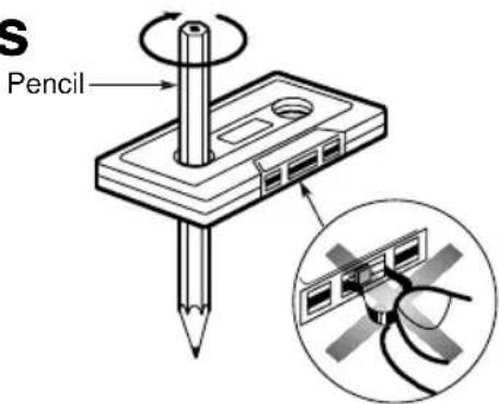
Do not touch or pull out the tape.
Notes:
- To maintain your cassette player in top condition, avoid using tapes that are longer than 90 minutes (C-90).
- If you insert into the unit a cassette with a loose tape caused by forcing it into cassette with a finger or the like, the cassette may not be properly reproduced. In such a case, eject the cassette, make the tape tight, then insert it back into the deck.
CD Changer Basics
Note: CD changer functions are applicable to units with optional CD changer unit. (sold separately)
To Changer mode
While a disc magazine inserted in the CD changer, press [MODE] to switch to changer mode. Play starts from the first track.

Selecting a Disc
Press [V DISC] or [DISC ∧] to select discs in descending or ascending order.
Selecting a Track
Press [TRACK ] once to go to the next track. Press repeatedly to step forward through all the tracks. Press [TRACK ] once to play from the beginning of the current track. Press twice to play the previous track. Press repeatedly to step backward through all the tracks.
Searching a Track
Press and hold [TRACK ] or [TRACK ] for more than 0.5 second to activate fast forward or reverse through a track. Release [TRACK ] or [TRACK ] to resume the normal CD play from that position.
CD Changer Basics continued
Repeating a Track
Press [4] (REPEAT) to repeat the current selection. "REPEAT" indicator lights.
REPEAT
The current selection continues to repeat until you press [4] (REPEAT) again.
Random Selection
- Press [5] (RANDOM) to random selection of music is played from all available CDs. "RANDOM" indicator lights.
RANDOM
To turn it off, press [5] (RANDOM) again.
Scanning Tracks
- Press [3] (SCAN). The track number blinks and the first 10 seconds of each track on the discs play in sequence.
- To stop scanning and continue with the current track, press [3] (SCAN) again.
012

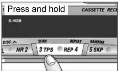
Scanning Discs
Press and hold [3] (SCAN) for more than 2 seconds. The 1st track of all the discs in the magazine is played for 10 seconds each. Also, Disc Number blinks at the same time. To stop the current play of the disc scanning, press and hold [3] (SCAN) for more than 2 seconds again.
012

□ Error Display Messages
| E1 | Displays when the compact disc is dirty or upside down. Selects the next available compact disc. | E3 | Displays when the compact disc stops operating for some reason. Please contact your nearest authorized Panasonic Serviceter. |
| E2 | Displays when compact disc is scratched. Selects next available compact disc. | 0000 | Displays when there is no disc in the magazine. |
Clock Basics
(The clock system is 12-hours.)
Initial Time Setting
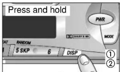
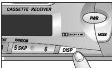
① Press and hold [DISP] for more than 2 seconds. "AdJ" is displayed.
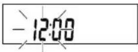
② Press and hold [DISP] again for more than 2 seconds. "12" blinks indicating the time setting mode is activated.
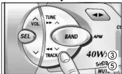
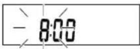
③ To set hours, press [A] or [V].
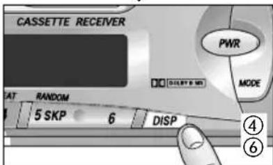
④ Press again [DISP] for minute setting.
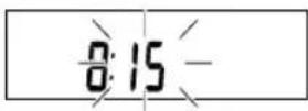
⑤ To set minutes, press [A] or [V]. Hold [A] or [V] to change numbers rapidly.
⑥ When you have set the time, press [DISP].


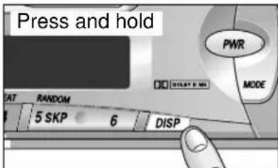
Resetting the Time
When you want to reset the time, press and hold [DISP] for more than 2 seconds to activate the time setting mode. Then, repeat step ③ to ⑥ above.
Selecting the Clock Display
Press [DISP] for clock display. Press [DISP] once again, the current audio display mode resumes.
When power is turned off while the time is displayed, the clock mode remains on. When [PWR] is pressed again, the system is completely off.
Remote Control Unit Preparation
Battery Installation
1 Remove the battery holder.
Take hold of the holder at position B and pull it out by pushing position A in the direction shown by the arrow.
Install the battery on the battery holder.
Set a new battery properly with its (+) side facing up as shown in the figure.
Insert the battery holder.
Push in the battery holder back into its original position.
Battery Notes
Remove and dispose of an old battery immediately.
Battery information:
- Battery Type: Panasonic lithium battery (CR2025) (Included)
- Battery Life: Approximately 6 months under normal use (at room temperature)
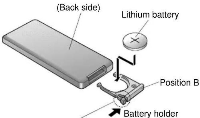
Position A
Caution:
Improper use of batteries may cause overheating, an explosion or ignition, resulting in injury or a fire. Battery leakage may damage the unit.
- Do not disassemble or short the battery. Do not throw a battery into a fire.
- Keep batteries away from children to avoid the risk of accidents.
- Be careful to the disposal rules when you dispose of batteries.
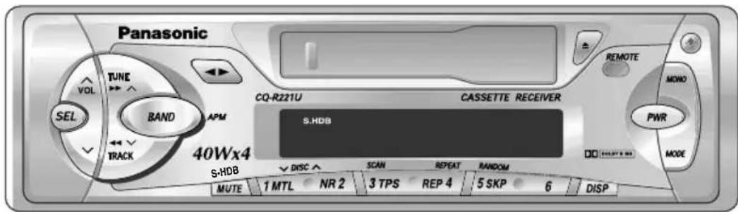
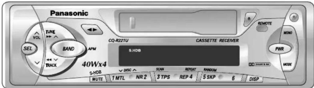
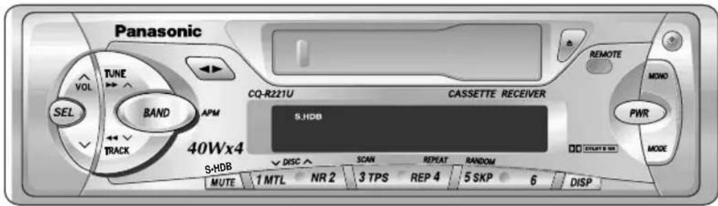
Main Controls

WARNING
This installation information is designed for experienced installers and is not intended for non-technical individuals. It does not contain warnings or cautions of potential dangers in attempting to install this product.
Any attempt to install this product in a motor car by anyone other than qualified installer could cause damage to the electrical system and could result in serious personal injury or death.
□Overview
This equipment should be installed by a professional. However, if you plan to install this unit yourself, your first step is to decide where to install it. The instructions in these pages will guide you through the remaining steps: (Please refer to "WARNING" statement above).
- Identify and label the vehicle wires.
- Connect the vehicle wires to the wires of the power connector.
Install the unit in the dash board. - Check the operation of the unit.
If you do encounter problems, please consult your nearest professional installer.
Caution: This unit will operate with a 12 volt DC negative ground auto battery system only. Do not attempt to use it in any other systems. Doing so could cause serious damage.
Before you begin installation, look for the following items included in the packing with your unit.
Installation Hardware
| No. | Item | Diagram Qty | |
| ① | Mounting Collar | 1 | |
| ② | Hex. Nut (5 mmφ) | 1 | |
| ③ | Rear Support Strap | 1 | |
| ④ | Tapping Screw (5 mmφ x 16 mm) | 1 | |
| ⑤ | Mounting Bolt (5 mmφ) | 1 | |
| ⑥ | Power Connector | 1 | |
| ⑦ | Dismounting Plate | 1 | |
| ⑧ | Removable Face Plate Case | 1 | |
Warranty Card . . . . . . . . Fill this out promptly
- Panasonic Servicenter for service
Directory . . .Keep this for future reference in case the unit needs servicing
- Installation Hardware . . . . . .Needed for in-dash installation
Installation Guide continued
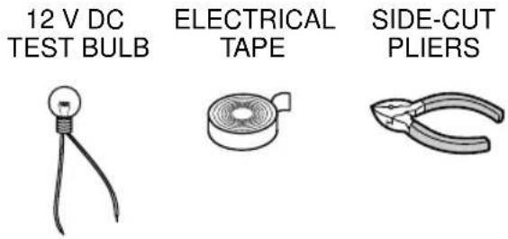
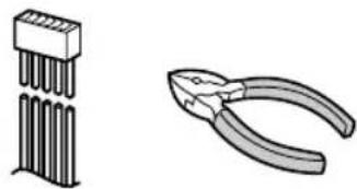
Required Tools
You'll need a screwdriver, a 1.5 volt AA battery, and the following:
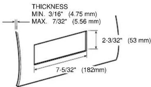
□ Dashboard Specifications
Identify All Leads
The first step in installation is to identify all the car wires you'll use when hooking up your sound system.
As you identify each wire, we suggest that you label it using masking tape and a permanent marker. This will help avoid confusion when making connections later.
Note: Do not connect the power connector to the stereo unit until you have made all connections. If there are no plastic caps on the stereo hooking wires, insulate all exposed leads with electrical tape until you are ready to use them. Identify the leads as follows.
Power Lead
If your car has a radio or is pre-wired for one: Cut the connector wires one at a time from the
plug (leaving the leads as long as possible) so that you can work with individual leads.
Turn the ignition on to the accessory position, and ground one lead of the test bulb to the chassis.
Touch the other lead of the test bulb to each of the exposed wires from the cut radio connector plug. Touch one wire at a time until you find the outlet that causes the test bulb to light.
Now turn the ignition off and then on. If the bulb also turns off and on, that outlet is the car power lead.
If your car is not wired for an audio unit :
Go to the fuse block and find the fuse port for radio (RADIO), accessory (ACC), or ignition (IGN).
Battery Lead
If your stereo unit has a yellow lead, you will need to locate the car's battery lead. Otherwise you may ignore this procedure. (The yellow battery lead provides continuous power to maintain a clock, memory storage, or other function.)
If your car has a radio or is pre-wired for one: With the ignition and headlights off, identify the car battery lead by grounding one lead of the test bulb to the chassis and checking the remaining exposed wires from the cut radio connector plug.
If your car is not wired for an audio unit :
Go to the fuse block and find the fuse port for the battery, usually marked BAT.
Speakers
Identify the car speaker leads. There will be two leads for each speaker, usually color coded.
A handy way to identify the speaker leads and the speaker they connect with is to test the leads using a 1.5 volt AA battery as follows.
Hold one lead against one pole of the battery and stroke the other lead across the other pole. You will hear a scraping sound in a speaker if you are holding a speaker lead.
If not, keep testing different lead combinations until you have located all the speaker leads. When you label them, include the speaker location for each.
Antenna Motor
If your car is equipped with an automatic power antenna, identify the car motor antenna lead by connecting one bulb tester lead to the car battery lead and touching the remaining exposed wires from the cut radio connector plug one at a time. You will hear the antenna motor activate when you touch the correct wire.
Antenna
The antenna lead is a thick, black wire with a metal plug at the end.
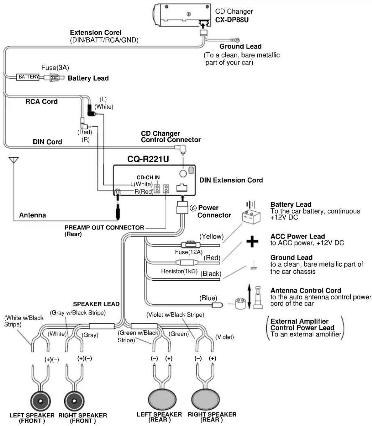
Connect All Leads
Now that you have identified all the wires in the car, you're ready to begin connecting them to the stereo unit wires. The connection diagram on Page 30 show the proper connections and color coding of the leads.
We strongly recommend that you test the unit before making a final installation.
You can set the unit on the floor and make temporary connections to test the unit. Use electrical tape to cover all exposed wires.
IMPORTANT: Connect the red power lead last, after you have made and insulated all other connections.
Ground
Connect the black ground lead of the power connector to the metal car chassis.
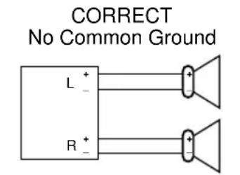
Speakers
Connect the speaker wires. See the wiring diagram below for the proper hookups. Follow the diagram carefully to avoid damaging the speakers and the stereo unit.
The speaker used must be able to handle more than 40 watts of audio power. If using an optional audio power, the speakers should be able to handle the maximum amplifier output power. Speakers with low input ratings can be damaged.
Speaker impedance should measure 4 - 8 Ω, which is typically marked on most speakers. Lower or higher impedance speakers will affect output and can cause both speaker and stereo unit damage.
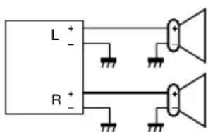
Caution: Never ground the speaker cords. For example, do not use a chassis ground system or a three-wire speaker common system. Each speaker must be connected separately using parallel insulated wires. If in doubt about how your car's speakers are wired, please consult with your nearest professional installer.
INCORRECT Common Chassis Ground
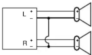
INCORRECT Speaker Common (common earth lead)
Installation Guide continued
Motor Antenna
Connect the car motor antenna lead to the blue motor antenna relay control lead.
Battery
Connect the yellow battery lead to the correct radio wire or to the battery fuse port on the fuse block.
Antenna
Connect the antenna by plugging the antenna lead into the antenna receptacle.
Product
Connect any optional product such as amplifier, according to the instructions furnished with the product. Keep about 12 inches (30 cm) of distance between the speaker cords/amplifier unit and the antenna/antenna extension cord. Read the operating and installation instructions for any product you will connect to this unit.
Power
Connect the red power lead to the correct car radio wire or to the appropriate fuse port on the fuse block.
If the stereo unit functions properly with all these connections made, disconnect the wires and proceed to the final installation.
Final Installation
Lead Connections
Connect all wires, making sure that each connection is insulated and secure. Bundle all loose wires and fasten them with tape so they won't fall down later. Now insert the stereo unit into the mounting collar.
Congratulations! After making a few final checks, you're ready to enjoy your new auto stereo system.
Final Checks
- Make sure that all wires are properly connected and insulated.
- Make sure that the stereo unit is securely held in the mounting collar.
- Turn on the ignition to check the unit for proper operation.
If you have difficulties, consult your nearest authorized professional installer for assistance.
Precautions
- When bending the mounting tab of the mounting collar with a screwdriver, be careful not to injure your hands and fingers.
- We strongly recommend you to wear gloves for installation work to protect yourself from injuries.
Installation Procedures
Note: Disconnect the cable from the negative (-) battery terminal.
1. Secure the Mounting Collar ①.
Insert Mounting Collar ① into the car's dashboard, and bend mounting tabs out with a screwdriver. Mounting Tab
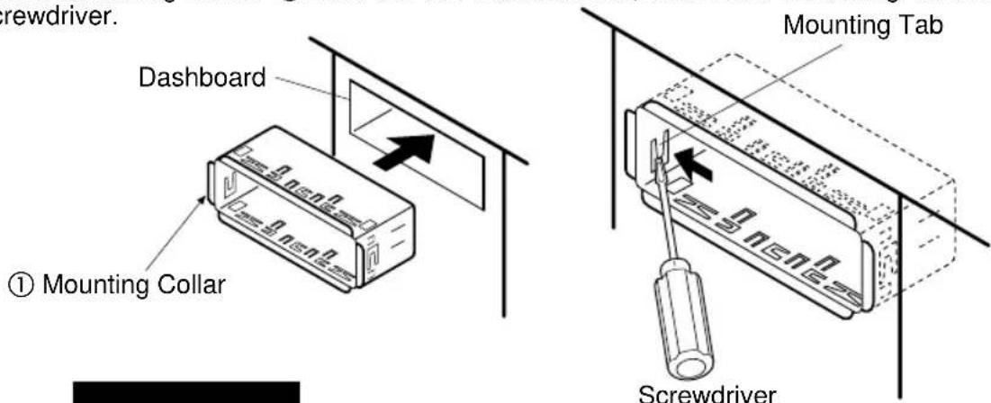
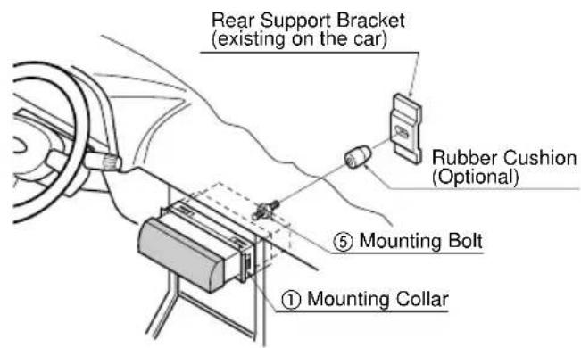
2. Secure the rear of the unit.
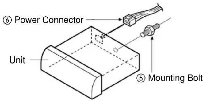
a) Check the electrical connection by referring to this operating instructions.
b) Connect the Mounting Bolt ⑤ using a suitable wrench.
c) Insert the Power Connector ⑥ to the unit.
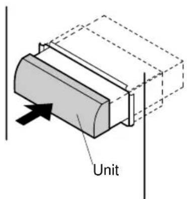
d) Insert the unit into Mounting Collar ① and push it in until "click" is heard.
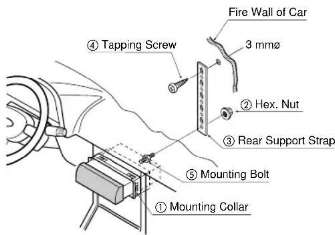
e) Secure the rear of the unit to the car by either of the two recommended methods as follows.
Using the Rear Support Strap ③
Affix one end of the Rear Support Strap ③ to the rear of the unit, and the other end to the Fire
Wall of Car, or some other metallic area.
Using the Rubber Cushion (Option)
(If there is an existing Rear Support Bracket on the Fire Wall of Car.)
Cover Mounting Bolt on the rear of the unit with Rubber Cushion (Option), and mount it into
the existing Rear Support Bracket.
3. After installation, reconnect the negative (-) battery terminal.
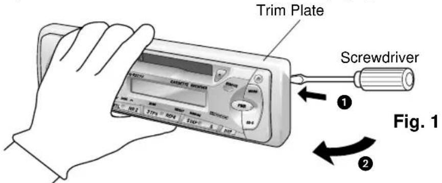
Installation Guide continued To Remove the Unit
a) Remove the trim plate with a screwdriver as shown in the figure (Fig. 1).
b) Pull out the unit while pushing the two lock levers using Dismounting Plate ⑦ as follows. (Fig. 2, 3)
c) Remove the unit pulling with both hands. (Fig. 4).
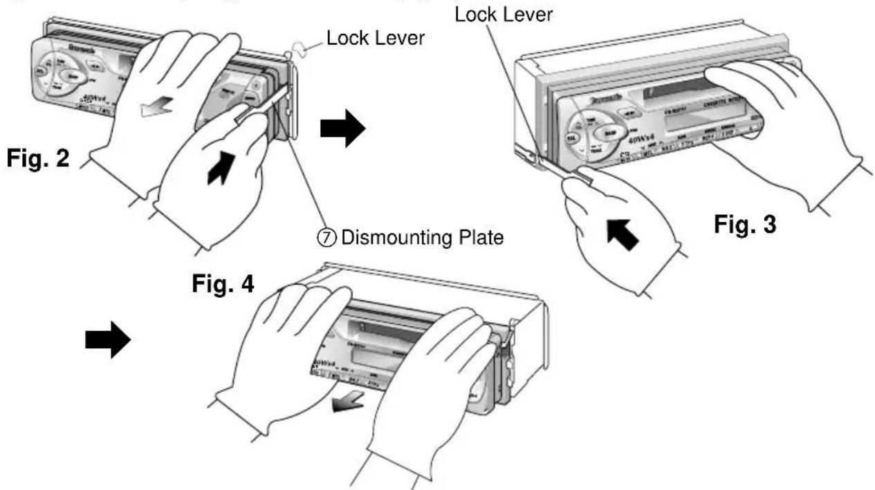
Note: Do not lose the Dismounting Plate. It will be needed to remove the unit from the car's dashboard.
Anti-Theft System
This unit is equipped with a removable face plate. By removing this face plate, the radio becomes totally inoperable. The security indicator will blink.
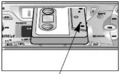
To Remove the Removable Face Plate
① Switch off the power.
② Press the release button (Fig. 5). The removable face plate will be released.
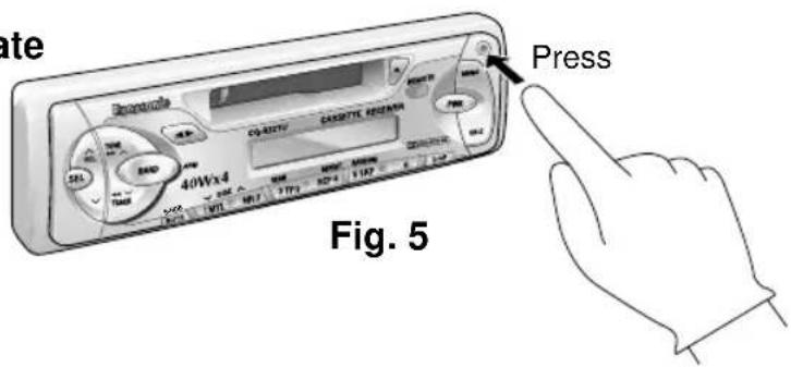
③ Remove the removable face plate by pulling on the right side of the unit. Place the removable face plate in a supplied case.
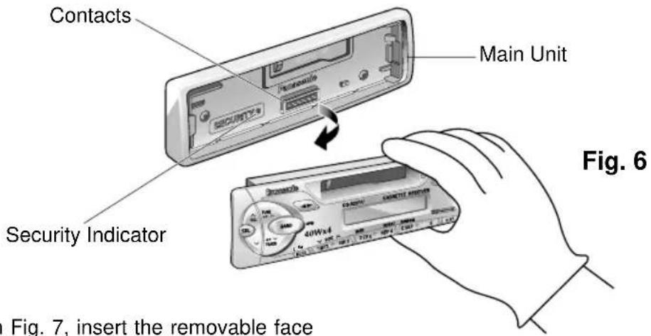
As shown in Fig. 7, insert the removable face plate with the arrow pointing toward the removable face plate case until you hear a "click". Keep the removable face plate in the case. Then, you can bring the plate safely.
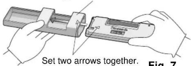
⑧RemovaleFacePlateCase
Fig. 7
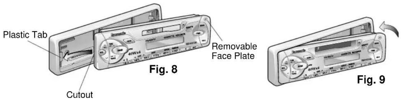
To install the Removable Face Plate
① Slide the left side of the removable face plate in place.
② Press the right end of removable face plate until "click" is heard.
Cautions:
- Before removing the removable face plate, make sure the power is off.
- This removable face plate is not water-proof. Do not expose it to water or excessive moisture.
- Do not remove the removable face plate while driving your car.
- Do not place the removable face plate on the dashboard or nearby areas where the temperature rises to high levels.
- Do not touch the contacts on the removable face plate or on the main unit, since this may result in poor electrical contacts.
- If dirt or other foreign substances get on the contacts, wipe them with a clean, dry cloth.
Electrical Connection
- This unit can be connected to an optional CD changer (CX-DP88U). For details consult your nearest Panasonic Servicenter.
- For connection to a CD changer, refer to the operating instructions of the CD Changer (CX-DP88U).
Cautions:
- To prevent damage to the unit, be sure to follow the connection diagram below.
- Remove the covering of the leads about 5mm long from their end before connecting.
- Do not insert the power connector into the unit until the wiring is completed.
- Be sure to insulate any exposed wires from a possible short-circuit from the car chassis. Bundle all cables and keep cable terminals free from touching any metal parts.
Troubleshooting
□ Maintenance
Your product is designed and manufactured to ensure a minimum of maintenance. Use a soft cloth for routine exterior cleaning. Never use benzine, thinner, or other solvents.
□When Something Doesn't Work
Check the charts below for possible causes and solutions to any problem you might be experiencing. Some simple checks or minor adjustments may eliminate the problem.
Product Servicing
If the suggestions in the charts don't solve the problem, we recommend that you take it to your nearest authorized Panasonic Servicenter. The unit should be serviced only by a qualified technician.
□ Replacing the Fuse
Use fuses of the same specified rating (12 amps). Using different substitutes or fuses with higher ratings, or connecting the unit directly without a fuse, could cause fire or damage to the stereo unit.
If the replacement fuse fails, contact your nearest authorized Panasonic Servicenter for service.
Troubleshooting Tips
| PROBLEM POSSIBLE CAUSE PROBABLE SOLUTION | ||
| Unit will not turn on. Dead car | batteryIgnition not on.Bad power line connection.Fuse burned out. | Charge car battery.Turn ignition to On or Accessory.Check connections.Replace fuse. |
| Radio has static. Antenna not hooked up.Close to high power lines. | Hooked up.High power lines. | Hook up antenna.Move away from high power lines. |
| Radio memory buttons do not work.Not holding buttons down long enough. | Not holding buttons down long enough. | Press and hold buttons for more than 2 seconds. |
| Tape sound quality is poor. Heads are dirty.Poor quality tape. | Clean heads.(Ask a service representative for advice.)Use better quality tape. | |
| Tape will not change programs.Not pressing [▶] and [←] buttons at the same time. | Press [▶] and [←] buttons at the same time. | |
| CD Changer will not operate.Unit not properly connected.Unit not switched into CD Change mode.No CDs in the magazine. | Check connections.Press [MODE].Check disc magazine. | |
| CD Changer will not play a specific disc.Disc loaded upside down.Disc damaged.Disc not loaded in magazine. | Reload disc properly.Check disc for scratches, chips.Check disc magazine. | |
Specifications
GENERAL
Power Supply: 12 V DC (11 V - 16 V) Test Voltage 14.4 V, Negative ground
Maximum Power Output : 40 W x 4 channels at 400 Hz, Volume Control maximum
Tone Action : Bass ; ± 12 dB at 100 Hz
Treble; ± 12 dB at 10kHz
Current Consumption : Less than 2 A (tape mode, 0.5 W 4-speaker)
Pre-Amp Output Voltage: 2.0 V (CD Play mode; 1kHz 0 dB)
Speaker Impedance : 4 Ω (4 - 8 Ω acceptable)
Dimensions (W× H× D):7''× 1 - 15 / 16''× 5 - 7 / 8'' ( 178× 50× 150mm)
Weight : 3 lbs. 8 oz. (1.6 k
AM RADIO
Frequency Range: 530 - 1,710 kHz
Useable Sensitivity: 28dB / V (25 V/ S/N 20 dB)
FM STEREO RADIO
Frequency Range: 87.9 - 107.9 MHz
Useable Sensitivity: 13.2dBf (1.25 V / 75)
50 dB Quieting Sensitivity: 15.2 dBf. (1.6 V/75Ω)
Frequency Response : 30 - 15,000 Hz ±3 dB
Capture Ratio : 1.5 dB
Alternate Channel Selectivity : 75 dB
Stereo Separation : 35 dB at 1,000Hz
Image Response Ratio : 65 dB
IF Response Ratio : 100 dB
Signal/Noise Ratio : 70 dB
TAPE PLAYER
Reproduction System : 4-track, 2-program stereo
Tape Speed : 1-7/8"/sec (4.76 cm/sec)
FF/REW Time :Less than 110 sec (C-60)
Frequency Response : 35 - 14,000 Hz ±3 dB (normal)
: 35 - 17,000 Hz ±3 dB (metal)
Wow and Flutter : 0.12 % (WRMS)
Signal/Noise Ratio : 52 dB, 62 dB (Dolby B NR on)
*Above specifications comply with EIA standards.
Note:
Specifications and design are subject to modification without notice due to improvements in technology.
| FM1 FM2 FM3 AM | ||
| 6 stations 6 stations 6 stations 6 stations | ||
S·HDB (Super High Definition Bass)
Congratulations! Besides, consider placing a few more things on your home page.
Para guitar el aparato
Panasonic Consumer Electronics Company, Division of Matsushita Electric Corporation of America
One Panasonic Way, Secaucus, New Jersey 07094
http://www.panasonic.com
Panasonic Sales Company.
Division of Matsushita Electric of Puerto Rico, Inc. ("PSC")
Ave. 65 de Infanteria, Km. 9.5
San Gabriel Industrial Park, Carolina,
Puerto Rico 00985
www.panasonic.com
Panasonic Canada Inc.
5770 Ambler Drive, Mississauga, Ontario L4W 2T3
www.panasonic.ca
