
DHU935HME - Range hood BOSCH - Free user manual and instructions
Find the device manual for free DHU935HME BOSCH in PDF.
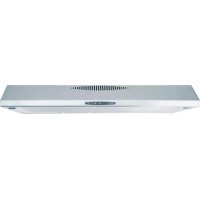


| Product type | Range hood |
| Brand | Bosch |
| Model | DHU935HME |
| Width | 90 cm |
| Weight (air extraction) | 9,7 kg |
| Weight (air recirculation) | 10,2 kg |
| Power supply | 220-240 V, 50 Hz |
| Power cable length | 1,30 m |
| Exhaust duct diameter | 100 mm |
| Lighting | 2 x 40 W max, socket E14, 110 lux |
| Operating modes | Air extraction and air recirculation (with active carbon filter) |
| Controls | Speed button and light ON/OFF button |
| Grease filter | Fleece (disposable) or metal (washable) |
| Active carbon filter | Optional for recirculation mode, replace about once a year |
| Minimum distance above the hob | 50 cm (electric), 65 cm (gas or mixed) |
| Metal filter maintenance | Clean in dishwasher or by hand every 8 to 10 weeks |
| Fleece grease filter replacement | Every 8 to 10 weeks |
| Cleaning the hood | Hot water with dish soap or non-aggressive glass cleaner |
| Safety | Disconnect before maintenance; do not use without grille; do not flambé under the hood |
| Repairs | Reserved for a specialist; after-sales service by call |
| General information | Compliant with safety standards and WEEE directives |
Frequently Asked Questions - DHU935HME BOSCH
User questions about DHU935HME BOSCH
0 question about this device. Answer the ones you know or ask your own.
Ask a new question about this device
Download the instructions for your Range hood in PDF format for free! Find your manual DHU935HME - BOSCH and take your electronic device back in hand. On this page are published all the documents necessary for the use of your device. DHU935HME by BOSCH.
USER MANUAL DHU935HME BOSCH
Household Appliances
Operating Instructions
User Manual
Operating Instructions
Operating and Maintenance Instructions
Operating Instructions
Arabic
Operating Instructions 8
Installation Instructions
13
Installation Instructions 31
Operating Instructions 35
Operating Instructions 40
Operating Instructions 44
Installation Instructions 49
53
60
fig.1/1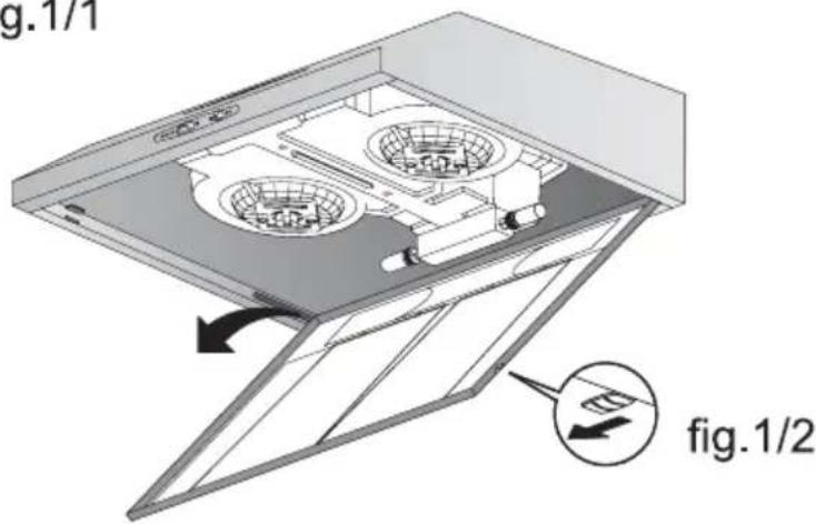
fig.2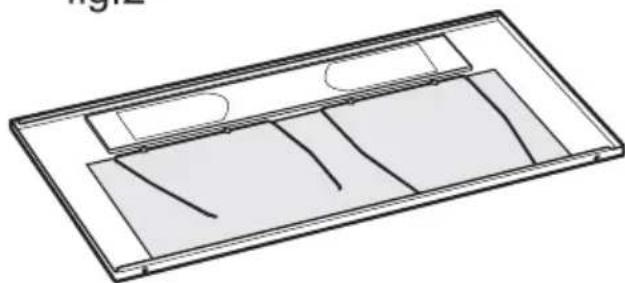
fig.3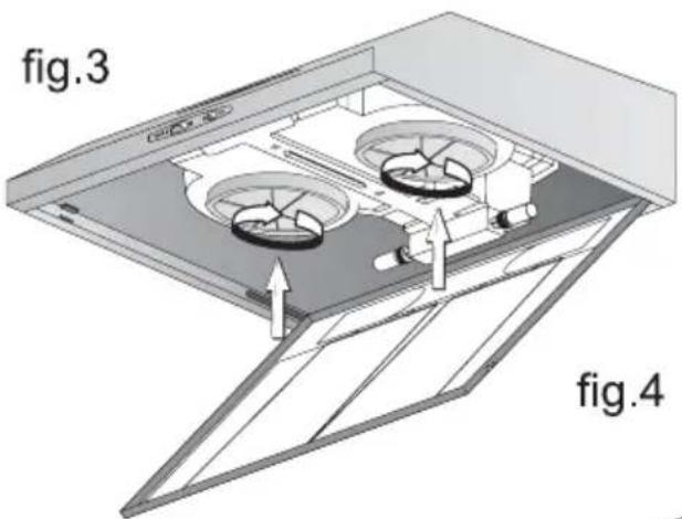
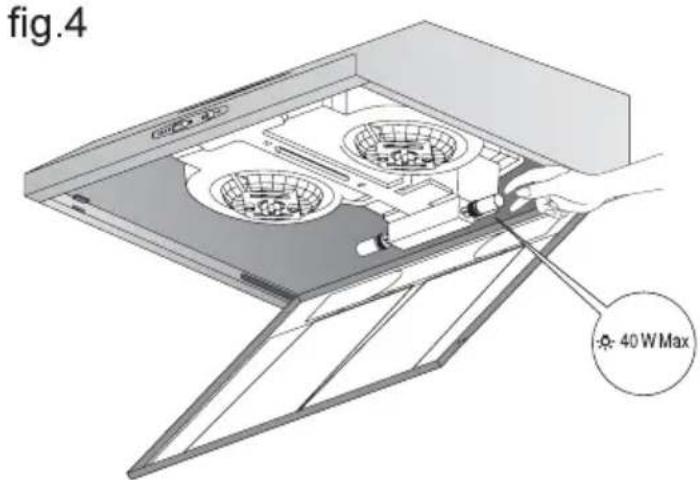
fig.5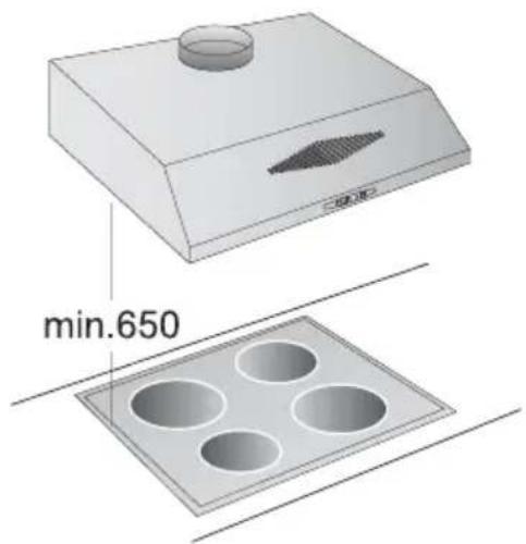
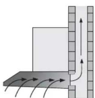
Fig.6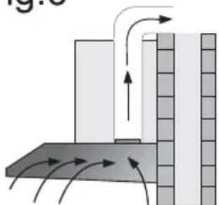
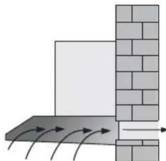
Fig.7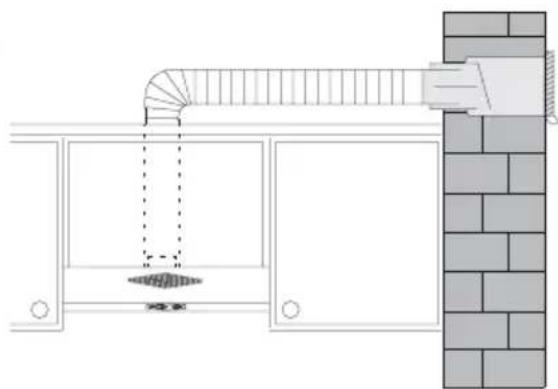
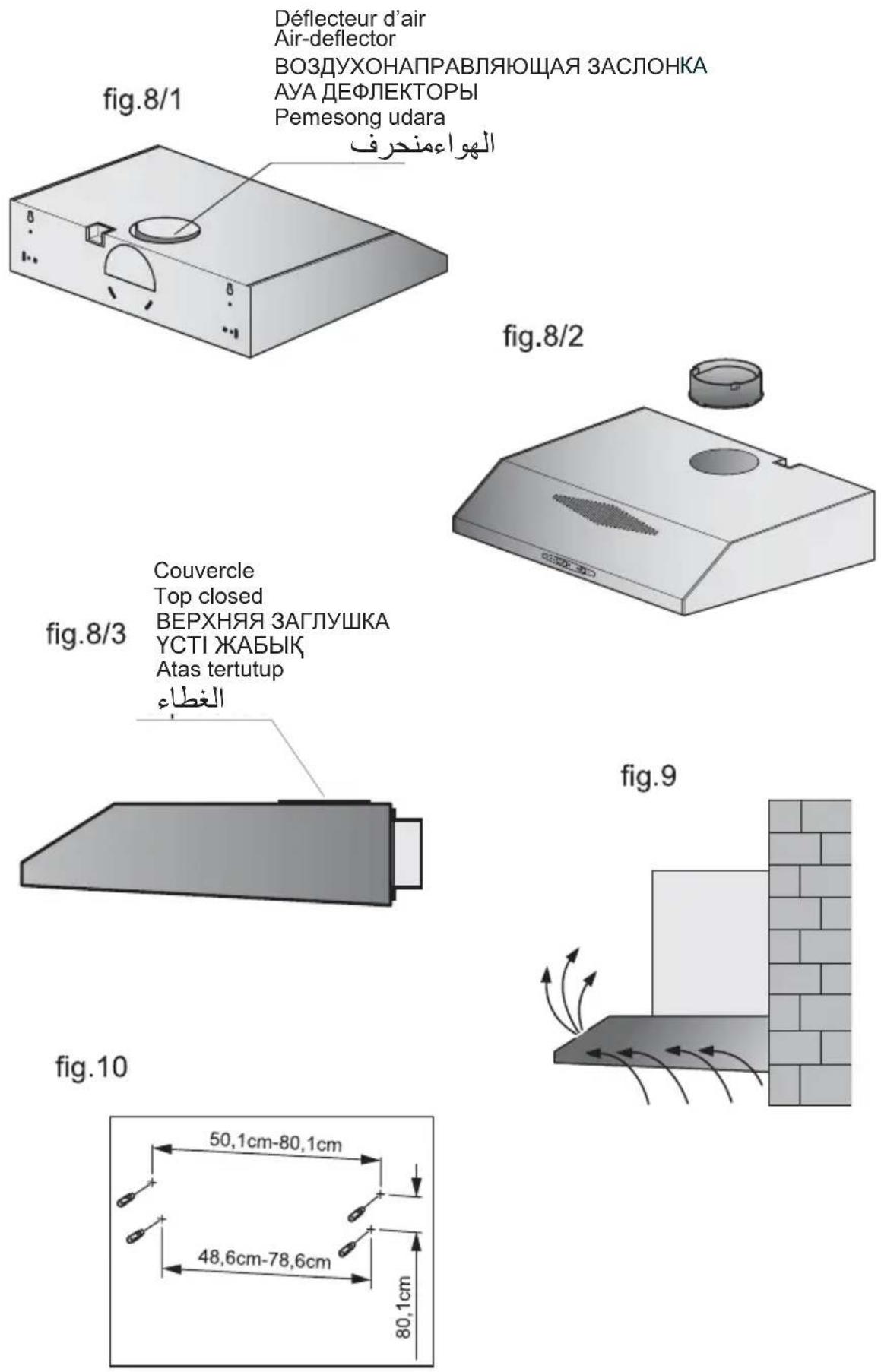
fig.11/1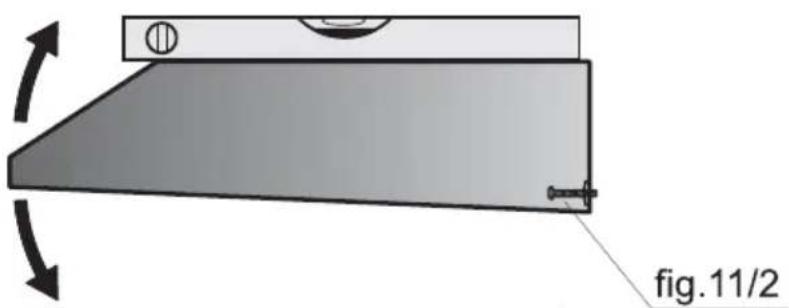
fig.12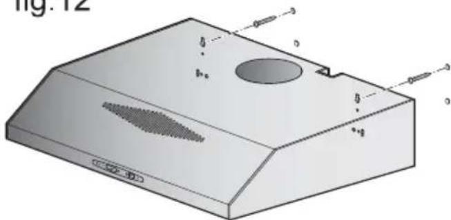
Description of appliance
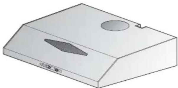
Operating modes
Exhaust-air mode:
The extractor-hood fan extracts the kitchen vapours and conveys them through the grease filter into the atmosphere. The grease filter absorbs the solid particles in the kitchen vapours. The kitchen is kept almost free of grease and odours.
Circulating-air mode:
An activated carbon filter must be fitted for this operating mode (see Filters and maintenance). The activated carbon filter can be purchased as an optional accessory from your dealer. The extractor-hood fan extracts the kitchen vapours which are purified in the grease filter and activated carbon filter and then conveyed back into the kitchen. The grease filter absorbs the grease particles in the kitchen vapours. The activated carbon filter binds the odorous substances. If the extractor hood is switched from exhaust-air mode to circulating-air mode, the exhaust-air opening must be sealed to prevent a hazardous situation (see optional accessories in the Instructions for use).
Before using for the first time
Important notes:
The Instructions for Use apply to several versions of this appliance. Accordingly, you may find descriptions of individual features that do not apply to your specific appliance. This extractor hood complies with all relevant safety regulations.
Repairs should be carried out by qualified technicians only.
Improper repairs may put the user at considerable risk.
Before using your appliance for the first time, please read these Instructions for Use carefully. They contain important information concerning your personal safety as well as on use and care of the appliance. Please retain the operating and installation instructions for a subsequent owner.
Dispose of packaging materials properly (see Installation instructions). This extractor hood is designed for domestic use only. Before any cleaning or maintenance operation, disconnect the hood from the mains by removing the plug or disconnecting the home mains switch. The appliance is not intended for use by children or persons with impaired physical, sensorial or mental faculties, or if lacking in experience or know-how, unless they are under supervision or have been trained in the use of the appliance by a person responsible for their safety. Children should be monitored to ensure that they do not play with the appliance. Never use the hood without effectively mounted grating. The hood must NEVER be used as a support surface unless specifically indicated. The premises must be sufficiently ventilated when the kitchen hood is used together with other gas combustion devices or other fuels.
Before using for the first time
The suctioned air must not be conveyed into a conduit used for the disposal of the fumes generated by appliances that combust gases or other fuels.
The flaming of foods beneath the hood itself is severely prohibited.
The use of exposed flames is detrimental to the filters and may cause a fire risk, and must therefore be avoided in all circumstances.
Any frying must be done with care in order to make sure that the oil does not overheat and burst into flames.
As regards the technical and safety measures to be adopted for fume discharging it is important to closely follow the relations provided by the competent authorities.
The hood must be regularly cleaned on both the inside and outside (AT LEAST ONCE A MONTH, it is in any event necessary to proceed in accordance with the maintenance instructions provided in this manual).
Failure to follow the instructions as concerns hood and filter cleaning will lead to the risk of fires.
Operating Instructions
Gas stoves and electric stoves
Do not use a gas hob with all the stoves on and top-powered for more than 15 minutes, otherwise the surface of the cooker hood might risk overheating, thus causing burns in case of contact with the hood.
Furthermore the cooker hood might get damaged.
In case more than 3 gas stoves are used, the cooker hood must be used at top power.
Important: a big stove having power higher than 5 KW (type WOK) corresponds to 2 standard stoves. Never use the gas stoves without any pots. Adjust the flame so that it does not exceed the perimeter of the pot.
! Do not use or leave the hood without the lamp correctly mounted because of the possible risk of electric shocks.
We decline any responsibility for any problems, damage or fires caused to the appliance as the result of the non-observation of the instructions included in this manual.
Operating the extractor hood Filters and maintenance
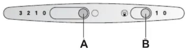
A Fan setting B Light ON/OFF
ATTENTION! Before performing any maintenance operation, isolate the hood from the electrical supply by switching off at the connector and removing the connector fuse.
Or if the appliance has been connected through a plug and socket, then the plug must be removed from the socket.
Grease Filter
Different grease filters can be used to absorb the grease particles in the kitchen vapours.
Fleece grease filter:
The filter mat consists of highly flammable material.
Warning:
A build up of greasy residue increases flammability, and the function of the extractor hood may be impaired.
Important:
Replace the fleece grease filter in good time, otherwise there is a risk of fire from the heat which accumulates during deep-fat frying or roasting.
Replacing the fleece grease filter:
During normal operation (daily 1 to 2 hours) the fleece grease filter must be replaced every 8 to 10 weeks. Replace printed fleece grease filters at the latest when the coloured print dissolves. Use only original filters. These comply with the safety regulations and ensure optimum function.
Disposal of the old fleece grease filter:
Fleece grease filters do not contain any harmful substances. They can be disposed of as bio-degradable waste.
Removing and installing the fleece grease filter:
- Press in the interlocks on the left and right sides of the filter grille. Fig. 1/1.
- Remove the filter grille. Fig. 1/2.
Filters and maintenance
- Remove the wire grille and the saturated filter mat. Fig. 2.
- Clean the filter grille and insert a new filter mat. Fig. 2.
- Clamp the filter mat with the wire grille. Fig. 2.
- Re-insert the filter grille. Fig. 1/2.
The interlocks must lock into position on the left and right sides. Fig. 1/1.
Metal grease filter:
The filter mats consist of non-flammable material.
Warning:
A build up of greasy residue increases flammability, and the function of the extractor hood may be impaired.
Important:
Replace the metal grease filter in good time, otherwise there is a risk of fire from the heat which accumulates during deep-fat frying or roasting.
Cleaning the metal grease filter:
During normal operation (daily 1 to 2 hours) the metal grease filter must be replaced every 8 to 10 weeks. The metal grease filter can be cleaned in the dishwasher.
Slight discoloration may occur.
Important:
Do not clean heavily saturated metal-grease filters with other dishes. If cleaning by hand, soak the grease filters in a hot soapy solution.
Then brush off any residual grease, rinse thoroughly and leave to dry.
Use only original filters.
These ensure optimum function.
Removing and installing the metal filter:
- Press in the interlocks on the left and right sides of the filter grille. Fig. 1/1.
- Remove the filter grille. Fig. 1/2.
- Remove the wire grille and the saturated
metal filter. Fig. 2.
- Clean the filter grille and the metal filter.
- Re-insert the cleaned metal filter and clamp them with the wire grille. Fig. 2.
- Re-insert the filter grille. Fig. 1/2.
The interlocks must lock into position on the left and right sides. Fig. 2/1.
Activated carbon filter:
For binding the odorous substances in circulating-air mode.
Installing:
- Press in the interlocks on the left and right sides of the filter grille. Fig. 1/1.
- Remove the filter grille. Fig. 1/2.
- Insert the activated carbon filter from below into the extractor-hood housing and lock into position by turning clockwise. (Fig. 3)
- Re-insert the filter grille. Fig. 1/2.
The interlocks must lock into position on the left and right sides. Fig. 1/1.
Removing:
The activated carbon filter is removed in reverse sequence.
Replacing the activated carbon filter:
During normal operation (daily 1 to 2 hours), the activated carbon filter must be replaced approximately once a year. The activated carbon filter can be purchased from your dealer. Use only original filters.
These ensure optimum function.
Disposal of the old activated carbon filter:
- Activated carbon filters do not contain any harmful substances. They can be disposed of as residual waste.
Cleaning and care
Isolate the extractor hood by pulling out the mains plug or switching off the fuse.
- When cleaning the grease filters, remove grease deposits from the accessible side of the housing. This will prevent a fire hazard and will ensure optimum function. Clean the extractor hood with a hot soapy solution or with a mild window cleaning agent.
- Do not scratch off dried-on dirt, but wipe it off with a moist cloth.
- Do not use any abrasive cleaning agents or scouring sponges. Note: Do not apply alcohol (spirit) to plastic surfaces, as they may tarnish.
Caution! Provide adequate ventilation in the kitchen. No naked flames.
Clean the switch only with a soft, moist cloth (mild soapy solution). Do not clean the switch with a stainless-steel cleaning agent.
Stainless-steel surfaces:
Use a mild, non-abrasive stainless-steel cleaning agent. Clean only in the direction of the ground surface. Do not clean stainless-steel surfaces with scouring sponges or with cleaning agents containing sand, soda, acid, or chlorides!
Replacing the lamps
Warning! Prior to touching the light bulbs, ensure they have cooled down.
- Switch off the extractor hood and isolate it by pulling out the mains plug or switching off the fuse.
- Remove the grease filter (see Filters and maintenance).
- Replace the lamp (commercially available candle lamps, max. 40 watts, E14 lampholder). Fig. 4.
- Reconnect the power by inserting the mains plug or by switching on the fuse.
Malfunctions
Please contact customer service regarding any queries or malfunctions.
When calling, please quote:
E-No.
FD
Enter the numbers in the above box. These numbers can be found on the rating plate - remove the grease filter inside the extractor hood to reveal the rating plate.
Important information
Old appliances are not worthless rubbish. Valuable raw materials can be reclaimed by recycling old appliances.
Before disposing of your old appliance, render it unusable.
This appliance is marked according to the European directive 2002/96/EC on Waste Electrical and Electronic Equipment (WEEE). By ensuring this product is disposed of correctly, you will help prevent potential negative consequences for the environment and human health, which could otherwise be caused by inappropriate waste handling of this product.
The symbol \(\mathbb{X}\) on the product, or on the documents accompanying the product, indicates that this appliance may not be treated as household waste. Instead it should be taken to the appropriate collection point for the recycling of electrical and electronic equipment. Disposal must be carried out in accordance with local environmental regulations for waste disposal.
For more detailed information about treatment, recovery and recycling of this product, please contact your local council, your household waste disposal service or the shop where you purchased the product.
You received your new appliance in a protective shipping carton.
All packaging materials are environmentally friendly and recyclable.
Please contribute to a better environment by disposing of packaging materials in an environmentally-friendly manner.
Please ask your dealer or inquire at your local authority about current means of disposal.
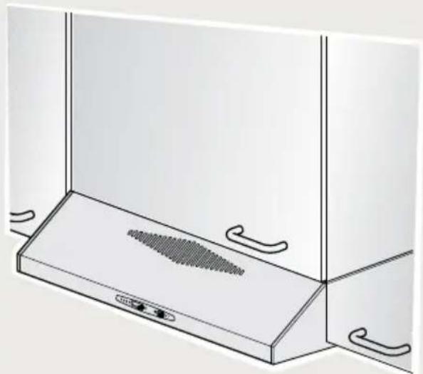
The extractor hood can be used in exhaust air or circulating air mode. Always mount the extractor hood over the centre of the hob. The minimum distance between the supporting surface for the cooking vessels on the hob and the lowest part of the range hood must be not less than \(50\mathrm{cm}\) from electric cookers and \(65\mathrm{cm}\) from gas or mixed cookers. Fig. 1
If the instructions for installation for the gas hob specify a greater distance, this must be adhered to.
Additional information for gas cooking appliances:
Comply with the currently valid installation regulations and the installation instructions supplied by the gas appliance manufacturers. The extractor hood may be installed with only one side next to a high-sided unit or at a high wall. Min. gap 50 mm The extractor hood must be installed at a minimum distance of 650 mm above gas hotplates - Fig. 5 - provided the following nominal heat loads (Hs) are not exceeded:
Gas cookers
Load of one hotplate max. 03.0 kW
Load of all hotplates max. 08.3 kW
Load of oven max. 03.9 kW
Gas hobs
Load of one hotplate max. 03.9 kW
Load of all hotplates max. 11.3 kW
Gas ceramic hob
The specifications for nominal heat load do not apply to closed gas ceramic hobs. Always comply with the specifications of the hotplate manufacturer.
The smaller the distance between the extractor hood and hotplates, the greater the likelihood that rising water vapour will condense under the extractor hood. The extractor hood may only be installed over a fireplace which burns solid fuel (fire hazard due to flying sparks) if the fireplace has a closed, non-detachable cover and national regulations have been observed. This restriction does not apply to gas cookers and gas hobs.
Before installation
Exhaust-air mode - Fig. 6
The exhaust air is discharged upwards through a ventilation shaft or directly through the outside wall into the open.
For operating in exhaust-air mode, a one-way flap should be mounted inside the wall ventilation box.
If no one-way flap was enclosed with the hood, it can be obtained from a specialist retailer.
If the exhaust air is going to be discharged into the open, a telescopic wall box should be fitted into the outside wall (Fig. 7).
For optimum extractor hood efficiency: use a short, smooth air exhaust pipe, as few bends as possible, and a pipe diameter as large as possible with no tight bends.
If long, rough exhaust-air pipes, many pipe bends, or smaller pipe diameters are used, the air extraction rate will no longer be at an optimum level and there will be an increase in noise.
Round pipes:
We recommend an internal diameter of:
100 mm
Flat ducts must have an internal cross-section that equates to that of round pipes.
There should be no sharp bends.
0 100 mm approx. 178 cm².
If pipes have different diameters: insert a sealing strip. For exhaust-air mode, ensure that there is an adequate supply of fresh air.
Exhaust air upwards:
Pipe diameter: 100 mm
Take care that the air-deflector is fitted (Fig. 8/1). Insert the exhaust-air connection (Fig. 8/2).
Exhaust air towards the rear:
Pipe diameter: 100 mm
Take out the air-deflector (Fig. 8/1). Insert the exhaust-air connection (Fig. 8/3). Close top exit with supplied jerk (Fig. 8/3).
Circulating-air mode (Fig. 9)
(If there is no exhaust-air mode option)
The air purified by an additional activated carbon filter is conveyed back into the room. For insertion of the activated carbon filter see Instructions for use. If the extractor hood is switched from exhaust-air mode to circulating-air mode, the exhaust-air opening must be sealed to prevent a hazardous situation.
Electrical connection
The appliance features an EU safety plug. To ensure protective earthing in a Danish socket, the appliance must be connected to a suitable plug adapter. This adapter (permitted up to max. 13 amps) is available from customer service (spare part no. 616581).
The mains power supply must correspond to the rating indicated on the plate situated inside the hood. If provided with a plug, connect the hood to a socket in compliance with current regulations and positioned in an accessible area. If it is not fitted with a plug (direct mains connection) or if the plug is not located in an accessible area, apply a bi-polar switch in accordance with standards which assures the complete disconnection of the mains under conditions relating to over-current category III, in accordance with installation instructions.
Warning! Before re-connecting the hood circuit to the mains supply and checking the efficient function, always check that the mains cable is correctly assembled.
Warning! Power cable replacement must be undertaken by the authorized service assistance centre or similar qualified person.
Connect the hood to a norm complying plug only. The plug should be located in an accessible zone.
The plug must be equipped with a protection circuit. If after installation the plug cannot be reached, a disconnecting device must be envisaged.
Fixed installation:
The fixed installation can be carried out by a qualified and authorized person only. Envisage an omnipolar switch having a contact opening of at least 3 mm, including an automatic circuit breaker.
The cable must be replaced by the manufacturer, the assistance centre or a qualified and authorized person only, in order to avoid any dangers.
Electrical data:
The technical data of the device are on the distinctive label inside the device behind the grease filters.
In case of repair, disconnect the electric supply from the cooker hood.
Length of the feeding cable: 1.30 m.
The hood complies with the EMC directives.
Fitting the extractor hood Final assembly
To the wall
60 cm wide extractor hood: With 4 screws. Fig. 10.
90 cm wide extractor hood:
With 4 screws. Fig. 10.
- Mark mounting boreholes. Dimensions can be found in Fig. 10 or use template.
- Drill 6 mm dia. holes and insert wallplugs flush with the wall.
- Screw in the upper screws (on left and right) until there is a gap of approx. 7 mm between the screw head and the wall.
- Remove the filter grille (see Instructions for use)
- Attach the extractor hood.
- If the cooker hood is not in perfect horizontal level (fig. 11/1), adjust it by using the adjusting screws (fig. 11/2).
- Tighten the lower screw (with washer) inside the extractor hood. Fig. 12.
To a wall-hanging cupboard
60 cm wide extractor hood:
With 4 screws. Fig. 13.
90 cm wide extractor hood:
With 4 screws. Fig.13.
- Dimensions for the mounting boreholes can be found in Fig. 13, or place a template on the base of the wall-hanging cupboard.
- Mark the mounting holes and make pilot holes with a bradawl. Fig. 13.
In exhaust-air mode (upwards) mark the exhaust-air opening and saw out. Fig. 13.
Consider the location of the connection cable; if required, saw out the cupboard. 3. Remove the filter grille (see Instructions for use). 4. Screw the extractor hood to the base of the cupboard. Fig. 14.
Extractor hood
Selecting the operating mode Fig. 15:
Exhaust-air mode: Position 1 Circulating-air mode: Position 2 Connect to the power supply. Insert the filter grille (see Instructions for use).
Specifications
Weight in kg:
in accordance with DIN 44971
| Width | Exhaust air | Circulating air |
| 60 cm | 8,2 | 8,7 |
| 90 cm | 9,7 | 10,2 |
Illuminance in lux:
110 Lux (2 x 40 Watt)
Design changes with respect to technical development shall remain withheld.
Protruding parts of the extractor hood can become very hot when using additional appliances for cooking.
Strictly observe all safety rules for extractor hoods and air ducts established in your country of residence.
Periodically carry out preventive cleaning of the interior and exterior of the extractor hood (at least once a month, strictly following the rules specified in this manual).
The manufacturer disclaims all liability for injuries or damage resulting from failure to observe the rules specified in this instruction manual.
Instruction manual
Gas and electric hobs, hot surfaces
Do not leave the hot surface with all burners on simultaneously for more than 15 minutes, as the surface of the extractor hood will become very hot, and contact with it can cause severe burns.
Moreover, this can damage the extractor hood itself.
If using 3 or more burners simultaneously, the hood must be used at maximum ventilation speed.
Attention: a 5 kW high-output burner corresponds to two standard burners. Do not leave a burner without a pot placed on it.
Operate the hood only with the lamps installed to prevent electric shock. The manufacturer disclaims all liability for injuries or damage resulting from failure to follow the instructions in this manual.
Hood control
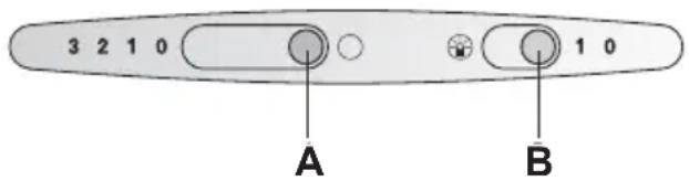
A Ventilation speed adjustment B Lighting on/off
Metal grease filters:
To capture the grease produced during cooking, metal grease filters are used.
The filter pads are made of non-flammable metal.
Attention:
Saturation of the filters with grease not only increases the risk of fire, but can also have a negative effect on the operation of the hood.
Important note:
Timely cleaning of the grease filters reduces the risk of fire.
Cleaning the metal grease filters:
To ensure good performance (1-2 hours per day), clean the filter every 8-10 weeks. The filter can be washed in a dishwasher. However, this may lead to slight discoloration. Install the filter freely in the dishwasher.
Important note:
Do not wash the contaminated metal grease filters in the dishwasher together with the dishes.
For hand washing, first soak them in hot soapy water. Then clean the filters with a brush, rinse them thoroughly in clean water and dry. Use only original filters to ensure optimal performance and durability of the hood.
Removal and installation of metal grease filters:
- Press the tabs on the grease filter. Fig. 1.1
- Remove the grid with the filter. Fig. 1.2
- Pull the contaminated filter out of the grid. Fig. 2
- Clean the grid and insert a new filter. Fig. 2
- Secure the filter to the metal grid. Fig. 2
- Install the grid back into the hood. Fig. 1.2 The tabs on the left and right will close automatically. Fig. 1.1
Charcoal filter:
Helps block cooking odors and fumes.
Installation:
- Press the tabs on the grid that holds the charcoal filter. Fig. 1/1
- Remove the grid and the filter. Fig. 1/2
- Insert the charcoal filter from bottom to top and secure it in the correct position, then lock it. Fig. 3
- Install the filter in place. Fig. 1/2 The latch on the left and right automatically locks the installed filter.
Fig. 1/1
Removal:
To remove, perform the above operations in reverse order.
Replacing the carbon filters:
For good operation of the hood (1-2 hours per day), replace the carbon filters approximately once a year. The carbon filter can be purchased at a specialized store (see paragraph "Special accessories"). Use only original carbon filters to ensure optimal performance and completeness of the set.
Disposal of the used carbon filter:
The carbon filters do not contain harmful substances. Dispose of them with normal household waste.
Cleaning and maintenance
Disconnect the hood from the electrical supply,
by pulling the plug out of the socket or switching off the circuit breaker.
Simultaneously with cleaning the grease filters (see paragraph "Filters and their maintenance"), clean all accessible parts of the housing from grease deposits. This significantly reduces the risk of fire and ensures optimal operation of the hood. For cleaning the hood, use a soft cloth dampened with a mild detergent solution for glass surfaces. Do not scrape off dried dirt, but soften it with a damp cloth. Never use abrasive cleaning agents or sponges that could scratch the surface. Note: Never clean plastic surfaces with alcohol, as matte stains may appear. Warning! Ventilate the kitchen frequently. Never leave an open flame! Clean the controls and knobs only with a mild soap solution and a damp cloth. Do not use stainless steel cleaners for the controls and knobs.
If the knobs are not included with the hood, they can be purchased at a specialized store.
Install the knobs inside the duct.
Check that nothing obstructs the free opening of the knob.
Install the telescopic air duct through the outer wall, as shown in Fig. 7.
Optimal exhaust efficiency is ensured when the following conditions are met:
Use short, flat exhaust pipes without sharp bends. Use a minimum number of elbows. Use pipes with as large an internal diameter as possible, and also use elbows with a large radius. In the case of using long, unevenly bent pipes of small diameter, the air exhaust speed will not reach the maximum effective level, and a noticeable increase in noise level is also possible.
Round pipes: internal diameter not less than 100 mm. Rectangular pipes must have a cross-sectional area equal to the cross-sectional area of the corresponding round pipes.
They must not have sharp bends.
In the case of pipes with an internal diameter of 100 mm, the cross-sectional area is approximately 178 cm².
If the pipes have different diameters: use a sealing tape. In the case of exhaust operation, ensure sufficient fresh air supply.
Air exhaust upward
Pipe diameter: 100 mm
Make sure the deflector is installed. (Fig. 8/1) □ Connect the air duct. (Fig. 8/2)
Air exhaust to the rear
Pipe diameter: 100 mm
Remove the deflector. (Fig. 8/1) □ Connect the air duct. (Fig. 8/3) Close the upper opening with the special cap included in the kit. (Fig. 8/3)
Air circulation mode Fig. 9
(Used when it is not possible to use the air exhaust mode)
The air exhaust duct enters the room from the rear. The filter used must comply with the requirements of the paragraph. When changing the operating mode, the exhaust air outlet must be properly closed to avoid dangerous situations.
Before installation
The exhaust hood should only be connected to a grounded socket installed in accordance with current regulations. If possible, the socket with grounding contact should be located directly behind the exhaust pipe. The socket with grounding contact should be connected via a separate electrical circuit. If after installation of the hood the socket with grounding contact is not accessible, a disconnecting device must be installed, as for fixed connection of the hood to the mains.
The electrical characteristics can be found inside the hood on a special label, which is located inside the hood body.
Attention! Before connecting the kitchen hood to the mains, make sure that all wires are connected correctly.
Attention! The hood must be connected to the mains only by a qualified electrician.
The hood should only be connected to a socket with grounding contact, installed in accordance with current regulations.
If possible, the socket with grounding contact should be located next to the hood. The socket with grounding contact must be connected via its own electrical circuit.
In case of need for fixed connection of the hood to the mains:
The hood must be connected to the mains only by a qualified electrician.
On the mains side, a disconnecting device must be installed. As disconnecting devices, devices that disconnect all contacts with a contact opening distance of at least 3 mm in the off state should be used. Automatic circuit breakers or contactors can be used as such disconnecting devices.
Electrical characteristics:
They can be found inside the hood on the label with technical characteristics, which is located behind the filter frame.
In case of repair, always disconnect the hood from the electrical network.
Length of connecting cable: 1.30 m.
This equipment complies with the requirements of the European Community regulations on radio interference.
Installation of the extractor hood
Wall-mounted model
Extractor width 60 cm:
4 screws Fig. 10.
Extractor width 90 cm:
4 screws. Fig. 10.
- Mark the drilling points; dimensions are shown in Fig. 10. Use the template. 2. Drill holes of 6 mm diameter and insert wall plugs flush with the wall.
- Secure with the upper screws (left and right), leaving the screw head about 7 mm from the wall.
- Remove the grease filter (see operating instructions).
- Install the extractor hood.
- If the extractor hood is not perfectly horizontal (Fig. 11/1), adjust its position using the adjustment screws (Fig. 11/2).
- Tighten the lower screws inside the extractor hood (using a ring spanner) Fig. 12.
Built-in model
Extractor width 60 cm:
4 screws. Fig. 13.
Exhaust air duct 90 cm:
4 screws. Fig. 13.
- Dimensions are shown in Fig. 13 or use the template.
- Mark the places for drilling, make the main holes with a drill. Fig. 13. Air duct outlet (top) Mark the hole for the air duct and drill it. Fig. 13. Determine the cable length, if necessary make a hole in the wall cabinet for the cable.
- Pull out the grille with filter (see operating instructions).
- Attach the extractor to the wall cabinet. Fig. 14.
Final assembly
Kitchen extractor
Select the operating mode. Fig. 15:
Air extraction mode: Position 1 Recirculation mode: Position 2 Connect the extractor to the power supply. Insert the grille with filter (see operating instructions).
Specifications
Weight in kg:
In accordance with DIN 44971
| ШирINA | Рек imm OTвоба ВОЗдуха | Рек imm циркулци ВОЗдуха |
| 60 cm | 8,2 | 8,7 |
| 90 cm | 9,7 | 10,2 |
Lighting: W
110 Lux (2 x 40 Watt)
The manufacturer reserves the right to make design changes for the purpose of technical improvement of the equipment.
KypaI cnnaattamacbi

Kymblc peximdepi
PaiandaHaBilFaH aya peXnMI:
By copfblw keiTeKlwi acy 6ynapbH sbIfapaDbI XeHe Onapbl MaN cy3rici apkblbl aTMocpepaFa xibepeDi. MaCy3rici acyn 6yIapbHdafb KaTTbl 6eKeTepdi ciipin aJadbl. AcyMaiMeHnicTepeHToIbIKdepNIK Ta3a6oJaBl.
AinhaMaJIbIayapeXnMI:
Before starting the device, read the operating instructions (for the user and for technical service). The device must be used only for its intended purpose. These operating instructions must be kept and must accompany the device if it is transferred to another user. The device must be cleaned before use. The device must be connected to the mains only after checking that the voltage corresponds to the value indicated on the nameplate. If the device is used in a way not specified in these instructions, the protection provided by the device may be impaired. See the section "Intended Use" in the operating instructions.
Before first use
Qualified personnel:
The operating instructions are part of the device. They must be kept in a safe place and must accompany the device if it is transferred to another user. These instructions contain important information for the safe operation of the device. Only trained technical personnel may open the housing. Other maintenance work must be carried out with caution. Before first use, read these instructions carefully. This is important for safety, but also for the correct operation and long service life of the device. Keep the operating and installation instructions for future use. Do not store the packaging materials carelessly (see installation instructions). ! These instructions are intended exclusively for trained personnel. Do not use the device for purposes other than those described in the operating instructions. ! This device may be used by children aged 8 and above and by persons with reduced physical, sensory or mental capabilities or lack of experience and knowledge if they have been given supervision or instruction concerning use of the device in a safe way and understand the hazards involved. Children must not play with the device. Cleaning and user maintenance must not be performed by children without supervision. ! Do not immerse the device in water or other liquids. ! Do not use the device near bathtubs, showers, or swimming pools. ! If the device is used in a bathroom, unplug it after use.
Before first use
Before using the device, check that the voltage corresponds to the value indicated on the nameplate.
During operation, keep the device away from flammable materials.
The bulbs may be used for both gas and electric, and it is possible to replace them with any type of bulb.
When the lamp is turned on, it may become hot, so it is necessary to install it securely to prevent any danger.
For this purpose, the technical characteristics of the device must be checked, and the electrical components must be installed without any risk.
The lamp and its outer surface must be cleaned regularly (if the user does not do this, it may affect the performance of the device).
The lamp and its components must be cleaned with a dry cloth.
Control devices
Gas and electric supplies
Do not leave the tank full of gas for more than 15 minutes, otherwise the lamp may overheat and cause a fire.
In addition, the lamp cover may also be closed.
When the gas supply is more than 3, the lamp cover must be closed to prevent overheating.
Note: The tank with a capacity of 5 kg can be connected to a standard gas supply. Do not use the gas supply without a regulator. The regulator must be installed on the perimeter of the tank.
Do not place the lamp near flammable materials, electrical wires, or water sources.
Do not use the device without proper installation, as it may cause electric shock or fire.
This is the control panel
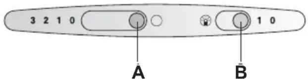
Electrical parameters in the control panel
Cy3rinep XəHe TexHnKaJIbIK Kbl3MeT KepceTy
HA3AP AYДAPbIHbI3! KaHdai da 6ip TexHNkaJIbIK KbI3MeT KepCeTy apeKeTIH opbIHdaMaCTah 6ypbIH, KockbIWTbI eWipy XHe KockbIUtBtIH CaKtaHDbIpRbIWBiH any apKbIbI KaKnaKTbI 3JeKTp KyaTbIHaH aXbIpaTbIHbI3.
Hemece KypaI aIbIp MeH po3eTKa apKbIbI KaIraHaH 6oJca, aIbIpDbI po3eTKaDaH any KaKeT.
Maç cy3rici
Acy6ynapbIHdaIbI MaB 6eKeTepiH ciHpy ywiH eptypni MaCy3ripePi naDanahyra 6oJaIbI.
Tykti MaCy3rici:
Cy3ri Tecehiwi eTe XaHfbiMiTepeHaJaH XacaIaNbl.
Eckey:
Kip KaIbIKTapdbIH XINHaIybi XaHfblWtBkTbI apTbIpaDbI XeHe 6y copfbIkwKaNarfbHbIH KymblcIH HaawapnATyb MYMkiH.
MaHbI3AbI:
Φnnc MaCy3riciHaKbITbIHda aybICTbIPbHbI3, 6oJmaca TepeH MaJa Kybpy Hemece nicipy 6apbcBHa XINHaTaBH XblNydaH eP T blyf KayPi TybIHdaNbl.
Tykti MaCy3ricin aybictbipy:
KanbITbI JyMbICbI 6apbcBHa (KyHHe 1 -2 carat) TYKTi MaN cy3rici ep 8-10 anTa caBH aybICTbIPbIybl Tnic. Opheri 6ap TYKTi MaN cy3rici H KEM DereHde TYCTi ePHEk epireH Ke3de aybICTbIPbIHbI3. TeK TynHcyKaIbI cy3rinepDi naDanaHbIHbI3. Onap kayinci3ik epexeepine caJ keJeI jxHe OHtaJIbI JxMbICTbI KaMTaMaCbI3 eTeI.
Ecki TykTi MaN cy3riciKOKbicka Tactay:
Tytimam cy3rinepiHH KypambHda eKanadn 3nHdbI 3aTTap KO. Onapbl 6noibiparfbI W KObc peIHDe Tactayra 6oanaB1.
Type of lubricant and its operating procedure:
- Lubricant brand name and its catalog number. Figure 1/1.
- Lubricant type. Figure 1/2.
Lubricants and technical service
- Drain the lubricant and clean the filter. Figure 2.
- Remove the lubricant tank cover and clean the lubricant filter. Figure 2.
- Clean the lubricant filter with the drain. Figure 2.
- Install the lubricant cover. Figure 1/2.
! Use only the specified lubricant and its operating positions. Figure 1/1.
Metallic lubricant:
The lubricant filter is made of metal material.
Caution:
Cleaning the filter increases its service life and prevents damage to the pump.
Note:
If the metallic lubricant is not used, deep wear or damage may occur during operation, which can lead to failure.
Metal oil change:
Change the metal oil (1-2 carats) every 8-10 months. The machine may be damaged. Follow the instructions.
Warning:
Do not mix metal oil with other liquids.
If you are not careful, the oil may spill. Wipe it up immediately. Then rinse with water and dry. Do not use harsh chemicals. They may damage the surface.
Removing and installing the metal oil filter:
1. Remove the filter cap without tools. Figure 1/1. 2. Remove the filter. Figure 1/2.
- Remove the filter and the metal oil filter. Figure 2.
- Remove the filter and the metal oil filter.
- Install the removed metal filter and secure it with the filter cap. Figure 2.
- Replace the filter cap. Figure 1/2.
The caps are for left and right positions. Figure 2/1.
Replacing the filter with a new one:
Designed to combine the parts of the air filter.
Installation:
- The device is designed for use with saline solution only. Figure 1/1.
- The device is ready for use. Figure 1/2.
- Remove the cap from the syringe and insert it into the device body, then turn it clockwise until it locks. (Figure 3)
- The device is ready for use. Figure 1/2.
Use only with saline solution. Figure 1/1.
Preparation:
Remove the syringe from its packaging.
To fill the syringe:
With the plunger fully depressed (1-2 hours), draw the saline solution into the syringe by pulling back once. The syringe can be filled to the desired level. The remaining solution can be discarded. They are not reusable. To dispose of the used syringe: The syringe components are not recyclable. Dispose of them in the regular trash.
Cleaning and Care
Do not pull or twist the device forcibly, as this may damage it.
If the device is not cleaned after use, the internal components may become contaminated. This can lead to infection. Clean the device with a soft cloth and mild soap. Do not use abrasive cleaners or sharp objects. Note: Do not use alcohol on plastic parts, as it may damage them.
Be careful! Do not use the device if it is damaged. If any part is missing, do not use it.
Clean the device only with a soft, damp cloth (do not immerse in water). Do not clean with any cleaning agents.
The device is not suitable for:
KymcaK, abpa3nBti eMec TOT 6acnaTbH 60aattbI Ta3aJafblw 3aTTbl KOJaHaHbIHbI3. Tek KaHa Teric 6eTTiH 6aftbImeH Ta3aJHaHbI3. !Tot 6acnaiTbIH 60nat 6eTTepi KblpfluI r6kaIapMeH HeMece KypamblHa Kym, cOda, KbllKbl Hemece Xnopntep 6ap Ta3aJafbl 3aTTapMeH Ta3aIamaHbI3!
Tazay XəHe Kyt
Eckenpy! Kapbik waMdpabHa TImecTeH 6ypbIH OJapdbIH cybIfaHDbIfbIHa Ke3 XeTKi3iHi3.
- By copfbiW kaKaNaFbH eWiipih3 XHe Kyat aibipbH TapTbIn WbIfapy Hemece caKaTaHdbipfBbITbI eWipy apKbInbI 6y copfbiW kaKaNaFbH axbipaTbIHbI3.
- Mai cy3ricin anbHbI3 (Cy3riep xhe TexHNkaJIbIK KbI3MeT Kepcety 6eJIIMiH kapaHbI3).
- 甲MdbI aybICTbIPbIHbI3 (caTbIN anyfa 60nATbIN 6aIaybI3 WAM TypiHderI naMna, 40 BATT, E14 nAmna natpoHbI). Cypet 4.
- KyaT aHbipbIH KaJfay Hemece caKaTaHDbIpfbIITbI KOCy apKbIbI KyaATbI KaTaNocBih3.
AkaaynbikTap
KaHdai da 6ip cypaynap HeMece akayIbIKTap 60nblHwa TytbIHyUbIapDbI KOJday KbI3MeTHe xa6apnaCbIHbI3.
KoHbIpay waIraH Ke3eKeNeciHaTbHbI3:
E-No. FD
Kofapbdafl epicke Hemipnepdi eHri3iHi3. Hemipnepdi TexnkaIbIK depekTepe TaTacbHaH Tabyfa 6oJaBt -TexnkaIbIK depekTepe TaTacbIH Kepy ywiH by copfbl KaKaNafbIHbIH iWihDeri Ma cy3rinepi h aNbIHbI3.
Ophaty aIdbiHda
MaHbI3dbI aKnapaT
Ecki Kypblfnbnap - naJacbi3 KObkic eMeC.
If the device is damaged, contact the service center for repair.
If the device is damaged, do not use it and contact the service center.
This device complies with the European Directive 2002/96/EC on Waste Electrical and Electronic Equipment (WEEE). This means that this product must not be disposed of as unsorted municipal waste, but must be collected separately for recycling.
The symbol (T) on the product or its packaging indicates that this product must not be treated as household waste. Instead, it should be handed over to an appropriate collection point for the recycling of electrical and electronic equipment. By ensuring this product is disposed of correctly, you will help prevent potential negative consequences for the environment and human health.
For more detailed information about recycling of this product, please contact your local city office, your household waste disposal service, or the shop where you purchased the product.
! Please keep the original cardboard packaging.
All packaging materials are recyclable and can be recycled.
Please do not dispose of packaging materials as household waste; instead, take them to a recycling collection point.
For more information about current disposal options, please contact your local waste management authority.
! This appliance can be used by children aged from 8 years and above and persons with reduced physical, sensory or mental capabilities or lack of experience and knowledge if they have been given supervision or instruction concerning use of the appliance in a safe way and understand the hazards involved. Children shall not play with the appliance. Cleaning and user maintenance shall not be made by children without supervision. ! Do not place the appliance on a hot surface or near an open flame. ! The minimum distance between the appliance and flammable materials should be at least 50 cm, and at least 65 cm from gas or other flammable sources. See Figure 1. ! If the power cord is damaged, it must be replaced by the manufacturer, its service agent or similarly qualified persons in order to avoid a hazard.
The following accessories are included with the appliance:
! Follow the installation instructions and the appliance's installation dimensions. The appliance's feet must be installed in accordance with the instructions. Minimum distance from the wall: 50 mm. ! The appliance must be installed at least 650 mm above the gas burners - see Figure 5. The appliance must be installed without the use of screws:
□ Gas burners
One burner
Max. 3.0 kW
Max. 8.3 kW
Electric system
Max. 3.9 kW
Gas burners
One burner power
Max. 3.9 kW
All burners power
Max. 11.3 kW
Ceramic gas burner
Nominal heat output ratings for standard ceramic gas burners are given. Please refer to the power supply specifications. ! If the distance between the burner and the cookware is too small, it may cause incomplete combustion. ! The burner should be cleaned regularly, and if there are any blockages or worn parts, they should be replaced. This applies to gas burners and gas cooktops.
During installation
Gas connection from the rear
Figure 6
The gas connection from the rear can be made through the rear panel or through the side panel.
For the prepared air mode, the air must be supplied to the ship's air system through a filter.
If this filter is not installed, they can be damaged by contaminants in the air.
If the prepared air is supplied externally, the air filter must be installed on the ship's air supply. See Figure 7.
For installation of the filter: short, tight air supply. The filter must be installed in a low position. The filter diameter must be larger than the pipe diameter, so that the pipe can be inserted. Long, tight air pipes, bent pipes or smaller pipe diameters can cause the air to be contaminated and increase noise. Recommended pipes:
Nominal diameter:
100 mm
The filter pipes should be at least 100 mm apart from each other. There should be no sharp bends. 100 mm gives 178 cm2. If the pipe diameters are different: use the larger cap. Check that the prepared air mode has clean air filters.
Air supply for heating:
Pipe diameter: 100 mm
Install the air deflector without a cap (Figure 8/1). Connect the prepared air supply (Figure 8/2).
Air supply for cooling:
Pipe diameter: 100 mm
Install the air deflector. Figure 8/1. Connect the prepared air supply (Figure 8/3) with the given saturator (Figure 8/3).
Air mode for heating
Figure 9
(If the device is not working)
The device is connected to the mains via a power cord. To connect the power cord, follow the instructions. If the device is connected to a power source other than the specified one, the device may be damaged.
Check the safety features of the device. To ensure safe operation, the plug must be inserted into the socket correctly. Do not use the device if the plug or socket is damaged (max. 13 A).
The device must be placed on a flat surface as shown in the figure. If the socket is not properly connected, the device may be damaged. If the socket is not working or is not properly grounded, contact a qualified electrician. Do not use the device in hazardous areas.
Warning! The device must be disconnected from the power supply before cleaning or maintenance.
Warning! The power cord must be replaced by a qualified person or a service center.
The device must be placed on a flat surface. Do not place it on an uneven surface.
The device must be placed on a stable surface. If the device falls, it may be damaged.
Installation:
The device must be installed by a qualified person. If the device is not working properly, contact a qualified person or service center. Do not attempt to repair the device yourself.
Electrical connections:
The technical specifications of the device are given in the table below.
In case of malfunction, disconnect the device from the power supply.
Power cord length: 1.30 m
The device complies with the EMC directives.
For 60 cm hood, 4 burners. Figure 10. For 90 cm hood, 4 burners. Figure 10. 1. Install the gas supply pipe. We have not connected the appliance to the gas supply. 2. Check the diameters of the pipes, connect them to the gas supply with a single connector. 3. Leave a gap of approximately 7 mm between the burner and the gas supply. Do not connect the upper burners (left and right). 4. Remove the plug (see installation instructions). 5. Secure the gas supply. 6. If the burner flame does not reach the thermocouple (Figure 11/1), adjust it with the adjustment screws (Figure 11/2). 7. Secure the lower burner (with the washer) inside the gas supply. Figure 12.
Installation
For 60 cm hood, 4 burners. Figure 13. For 90 cm hood, 4 burners. Figure 13. 1. Install the gas supply pipes, connect them according to the diagram in Figure 13 or to the base of the appliance. 2. Mark the installation dimensions and drill the mounting holes. Figure 13. Determine the gas supply direction (upward) and mark it. Figure 13. Note the cable routing; if necessary, make a hole. 3. Remove the plug (see installation instructions). 4. Secure the gas supply to the base of the hood. Figure 14.
Final installation
The gas supply
Gas type selection - Figure 15:
Gas type: 1st setting. Power level: 2nd setting. Remove the plug (see installation instructions).
Specifications
Gas consumption:
Complies with DIN 44971 standard
| Енi | Пайдалалынган aya | Ан haлимны aya |
| 60 cm | 8,2 | 8,7 |
| 90 cm | 9,7 | 10,2 |
Electrical connection:
110 W (2 x 40 W)
Technical data subject to change.
Tool description
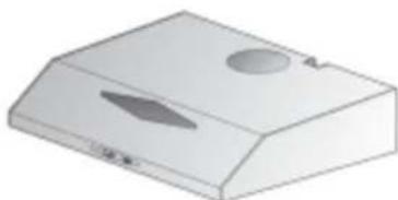
Control mode
Air exhaust mode:
1
(1)
2.11 k : k1 ≤ k < k
2.2 K. 1
2.2J5.
.2/1 Jsi. 6
1/11
a
Jia xu 2y jia yao jao ic gian
4
∴ E ( θ , - θ )
4
LbcIg
J 1
:
E-No FD
Therefore, the area of triangle ACD equals the area of triangle COD plus the area of triangle DCE.
abaae aee
Aa aee
alolo Cologlao
1 1
aaii jiai i jiaai 1jiaai 1jiaai jiaai jiaai jiaai jiaai jiaai jiaai jiaai
Jauuuiu aullue jie kglal iia aolll aaiill s jg 100a dill
(RAEE) 11111111111111111111111
aegn aagannnnn nss
aall aill glaalall alll gilll

- liang: 2020 National Volume 3 Question
- σ = | x - 3|
J 50:60
j 8
max. 03.0 kW: jzai
max. 08.3 kW: aiaaii iaii
max. 03.9 kW.
jul 1
max. 03.9 kW:
max. 11.3 kW: aiiuuii iuii iuii
jdyd jydi y
Clll aieaal as yll lalal gay lae
15 15
- DESCRIPTION OF APPLIANCE
- OPERATING MODES
- EXHAUST-AIR MODE
- CIRCULATING-AIR MODE
- BEFORE USING FOR THE FIRST TIME
- IMPORTANT NOTES
- OPERATING INSTRUCTIONS
- GAS STOVES AND ELECTRIC STOVES
- OPERATING THE EXTRACTOR HOOD FILTERS AND MAINTENANCE
- GREASE FILTER
- FLEECE GREASE FILTER
- WARNING
- IMPORTANT
- REPLACING THE FLEECE GREASE FILTER
- DISPOSAL OF THE OLD FLEECE GREASE FILTER
- REMOVING AND INSTALLING THE FLEECE GREASE FILTER
- FILTERS AND MAINTENANCE
- METAL GREASE FILTER
- CLEANING THE METAL GREASE FILTER
- USE ONLY ORIGINAL FILTERS
- REMOVING AND INSTALLING THE METAL FILTER
- ACTIVATED CARBON FILTER
- FOR BINDING THE ODOROUS SUBSTANCES IN CIRCULATING-AIR MODE
- INSTALLING
- REMOVING
- REPLACING THE ACTIVATED CARBON FILTER
- DISPOSAL OF THE OLD ACTIVATED CARBON FILTER
- CLEANING AND CARE
- ISOLATE THE EXTRACTOR HOOD BY PULLING OUT THE MAINS PLUG OR SWITCHING OFF THE FUSE
- STAINLESS-STEEL SURFACES
- REPLACING THE LAMPS
- WARNING! PRIOR TO TOUCHING THE LIGHT BULBS, ENSURE THEY HAVE COOLED DOWN
- MALFUNCTIONS
- IMPORTANT INFORMATION
- ADDITIONAL INFORMATION FOR GAS COOKING APPLIANCES
- GAS COOKERS
- GAS HOBS
- GAS CERAMIC HOB
- BEFORE INSTALLATION
- EXHAUST-AIR MODE - FIG
- MM
- EXHAUST AIR UPWARDS
- EXHAUST AIR TOWARDS THE REAR
- CIRCULATING-AIR MODE (FIG. 9)
- ELECTRICAL CONNECTION
- FIXED INSTALLATION
- ELECTRICAL DATA
- FITTING THE EXTRACTOR HOOD FINAL ASSEMBLY
- TO THE WALL
- TO A WALL-HANGING CUPBOARD
- EXTRACTOR HOOD
- SELECTING THE OPERATING MODE FIG
- SPECIFICATIONS
- WEIGHT IN KG
- ILLUMINANCE IN LUX
- INSTRUCTION MANUAL
- GAS AND ELECTRIC HOBS, HOT SURFACES
- HOOD CONTROL
- METAL GREASE FILTERS
- ATTENTION
- IMPORTANT NOTE
- CLEANING THE METAL GREASE FILTERS
- REMOVAL AND INSTALLATION OF METAL GREASE FILTERS
- CHARCOAL FILTER
- HELPS BLOCK COOKING ODORS AND FUMES
- INSTALLATION
- REMOVAL
- REPLACING THE CARBON FILTERS
- DISPOSAL OF THE USED CARBON FILTER
- CLEANING AND MAINTENANCE
- DISCONNECT THE HOOD FROM THE ELECTRICAL SUPPLY
- AIR EXHAUST UPWARD
- AIR EXHAUST TO THE REAR
- AIR CIRCULATION MODE FIG
- IN CASE OF NEED FOR FIXED CONNECTION OF THE HOOD TO THE MAINS
- ELECTRICAL CHARACTERISTICS
- INSTALLATION OF THE EXTRACTOR HOOD
- WALL-MOUNTED MODEL
- BUILT-IN MODEL
- FINAL ASSEMBLY
- KITCHEN EXTRACTOR
- LIGHTING: W
- KYPAI CNNAATTAMACBI
- KYMBLC PEXIMDEPI
- PAIANDAHABILFAH AYA PEXNMI
- AINHAMAJIBIAYAPEXNMI
- BEFORE FIRST USE
- QUALIFIED PERSONNEL
- CONTROL DEVICES
- GAS AND ELECTRIC SUPPLIES
- THIS IS THE CONTROL PANEL
- CY3RINEP XƏHE TEXHNKAJIBIK KBL3MET KEPCETY
- MAÇ CY3RICI
- TYKTI MACY3RICI
- ECKEY
- MAHBI3ABI
- TYKTI MACY3RICIN AYBICTBIPY
- ECKI TYKTI MAN CY3RICIKOKBICKA TACTAY
- TYPE OF LUBRICANT AND ITS OPERATING PROCEDURE
- LUBRICANTS AND TECHNICAL SERVICE
- METALLIC LUBRICANT
- CAUTION
- NOTE
- METAL OIL CHANGE
- REMOVING AND INSTALLING THE METAL OIL FILTER
- REPLACING THE FILTER WITH A NEW ONE
- DESIGNED TO COMBINE THE PARTS OF THE AIR FILTER
- PREPARATION
- TO FILL THE SYRINGE
- DO NOT PULL OR TWIST THE DEVICE FORCIBLY, AS THIS MAY DAMAGE IT
- THE DEVICE IS NOT SUITABLE FOR
- TAZAY XƏHE KYT
- ECKENPY! KAPBIK WAMDPABHA TIMECTEH 6YPBIH OJAPDBIH CYBIFAHDBIFBIHA KE3 XETKI3IHI
- AKAAYNBIKTAP
- E-NO. FD
- OPHATY AIDBIHDA
- MAHBI3DBI AKNAPAT
- THE FOLLOWING ACCESSORIES ARE INCLUDED WITH THE APPLIANCE
- GAS BURNERS
- CERAMIC GAS BURNER
- DURING INSTALLATION
- GAS CONNECTION FROM THE REAR
- AIR SUPPLY FOR HEATING
- AIR SUPPLY FOR COOLING
- AIR MODE FOR HEATING
- ELECTRICAL CONNECTIONS
- FINAL INSTALLATION
- THE GAS SUPPLY
- GAS TYPE SELECTION - FIGURE
- GAS CONSUMPTION
- TOOL DESCRIPTION
- CONTROL MODE
- AIR EXHAUST MODE
Brand : BOSCH
Model : DHU935HME
Category : Range hood