KIT.VPA.2FR02.BLB - Intercom Bellcome - Free user manual and instructions
Find the device manual for free KIT.VPA.2FR02.BLB Bellcome in PDF.

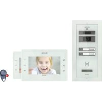
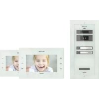
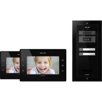
| Product type | Video intercom with 7" screen |
| Brand | Bellcome |
| Model | KIT.VPA.2FR02.BLB |
| Power supply | 230 V / 50 Hz via 6 A automatic fuses |
| Power consumption | Approx. 15 W (max) |
| Display | 7 inches, color |
| Main functions | Video call, hands-free conversation, door opening, video and audio surveillance, intercom, RFID badge, photo capture |
| Photo storage capacity | 100 photos |
| Conversation duration | 2 minutes max |
| Surveillance duration | 10 seconds |
| Number of ring melodies | 5 melodies |
| Image settings | Brightness, chrominance, contrast |
| Time settings | Time and date |
| Maintenance | Clean with a soft cloth; protect from corrosive substances, lime, dust |
| Safety | Do not open the central unit; disconnect fuses before intervention; protection against electric shocks |
| Warranty | 3 years |
| Dimensions (approximate) | Street panel: 130 x 90 x 30 mm; Indoor station: 200 x 150 x 30 mm; Central unit: 4 DIN modules (72 x 90 x 58 mm) |
| Weight (approximate) | Approx. 1.5 kg (complete kit) |
| Wiring type | RJ45 connectors or screw terminals |
| Operating temperature | 0 °C to 40 °C |
| Standards | CE |
Frequently Asked Questions - KIT.VPA.2FR02.BLB Bellcome
User questions about KIT.VPA.2FR02.BLB Bellcome
0 question about this device. Answer the ones you know or ask your own.
Ask a new question about this device
Download the instructions for your Intercom in PDF format for free! Find your manual KIT.VPA.2FR02.BLB - Bellcome and take your electronic device back in hand. On this page are published all the documents necessary for the use of your device. KIT.VPA.2FR02.BLB by Bellcome.
USER MANUAL KIT.VPA.2FR02.BLB Bellcome
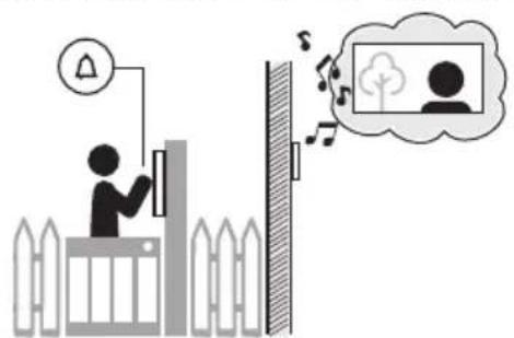
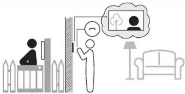
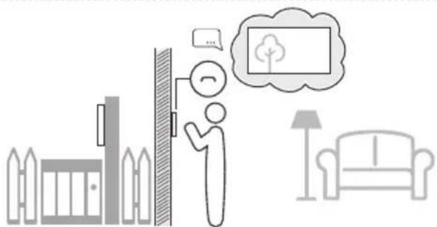
Video & Audio monitoring
Monitoring video & audio


6.Bilder Speicher
Pictures memory
Memoire d'images
Setting the ringing duration
Access with RFID tag
Accès à badge RFID
SAFETY INSTRUCTIONS during installation
- ATTENTION! The installation, the maintenance and the connection to the 230V/50Hz network of the central unit (SCU) will be carried out only by authorized personnel!
- ATTENTION! It is MANDATORY to use a 3 × 0.75 mm^2 cable and 2 automatic fuses (6A) for power supplying the central unit (SCU) from the 230V/50Hz network.
- ATTENTION! During installation, connection of the central unit (SCU) to 230V/50Hz and service, the safety fuses from the electric panel must be opened (.).POWER OFF
- ATTENTION! DO NOT UNFASTEN THE FRONT LID OF THE CENTRAL UNIT (SCU)! DANGER OF ELECTRIC SHOCK! Only 1 and 2 protection lids of the connections can be unfastened during installation or service.
- IMPORTANT! You must make the connections for F, N and and mount the 1 and 2 protection lids of the central unit (SCU) and only after these you can connect the 2 supply fuses (230V/50Hz)
- DO NOT TOUCH the metallic parts of the wires or the terminals of the connectors from the central unit (SCU) or from the fuses. You have to disconnect first the 6 A fuses (POWER OFF) from the supply's phase and only then you can work with the central unit (SCU).
- ATTENTION! Do not supply components of the installation separately (outdoor panel, terminals etc.) at voltages higher than 14Vd.c. or directly from the network (230V/50Hz). DANGER OF ELECTRIC SHOCK and system destruction.
- PAY ATTENTION to the polarity of the terminals of the rechargeable battery (max. 7 Ah/ 12 Vd.c.) when connecting it to the central unit (SCU).
4.1. Installation steps
| Step 1 | Install the Outdoor Panel (VPA) - Ch. 5.2. The electrical connections must be in accordance with the diagram from Ch. 5.2.6. |
| Step 2 | Install the Video Connection Box (VCB) - Ch. 5.3. (2 and 3 Families - 3.1.2, 3.1.3) For connections with RJ45 connector - Ch. 5.3.2. For connections with screw connectors - Ch. 5.3.3. |
| Step 3 | Install the Video Terminal (VTA) - Ch. 5.4. For connections with RJ45 connector - Ch. 5.4.2. For connections with screw connectors - Ch. 5.4.3. For additional video terminal - Ch. 5.4.4. For additional audio terminals - Ch 5.4.5. |
| Step 4 | Install the Central Unit (SCU) - Ch. 5.5. Authorized personnel required! - Ch. 4 With the 6A automatic fuses in OFF position: a. Place the SCU in the electric panel - Ch. 5.5.1. b. Make in the SCU the connections for VPA, VTA (LCK, Vcam, e.t.c.) - Ch. 5.5.2/ 5.5.3. (5.5.4., 5.5.5.) c. Make the F, N and connections in SCU. d. Make the F, N connections at the automatic fuses and to the ground. |
| Step 5 | Check the precision of all the connections made in SCU - Ch. 5.5.2/ 5.5.3. |
| Step 6 | Turn ON the 6A automatic fuses. |
| Step 7 | Check the LEDs colors of SCU - Ch. 6.3. In case of red signaling of any LED, turn OFF the 6A automatic fuses and see TROUBLESHOOTING - Ch. 7 to identify the cause. |
| Step 8 | With a voltmeter set on direct current, check the voltages on the terminals of SCU - Ch. 5.6.1., VPA - Ch. 5.6.2. and VTA / VCB - Ch. 5.6.3. If the values do not match, see TROUBLESHOOTING - Ch. 7 and identify the cause. |
| Step 9 | Check the correct functioning and settings changing - Ch. 6.4.1, 6.5.1., 6.5.2. |
Installation of the outdoor panel
Antitheft protection. Screw the Torx 2 completely!
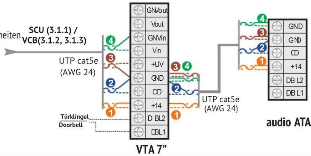
Electrical connections
Installation of the video connection box (for 2 and 3 families)
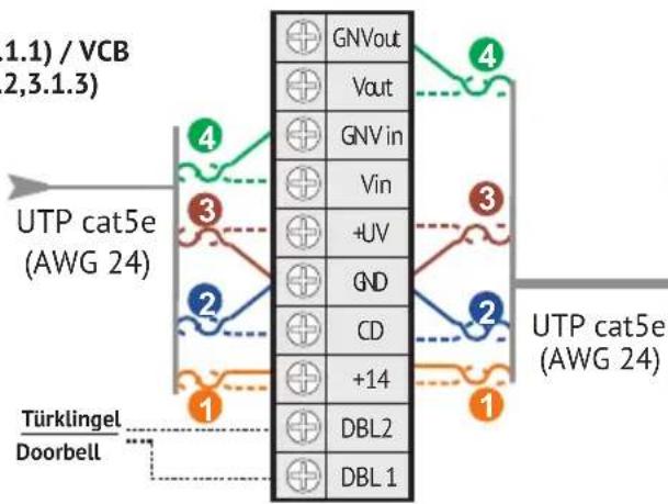
Electrical connections with RJ45 connector
Electrical connections with screw connectors
VTA 7"
video VTA 7" (VTT3,5")
| GNVout | |
| Vout | |
| GN Vin | |
| Vin | |
| +UV | |
| GND | |
| CD | |
| +14 | |
| DBL2 | |
| DBL1 |
5.4.5

Zusätzliche Audio Innenein Additional audio terminals Postes interieurs audio supplémentaires
Terminale audio adizionale Extra audio terminals Dodatkowe terminale audio
5.5. SCU


5.5.1
Einbau der Stromversorungseinheit Installation of the central unit Installation de l'unité centrale Installatione dell'unità centrale Installatie van de centrale eenheid Instalacja jegnostki centralnej
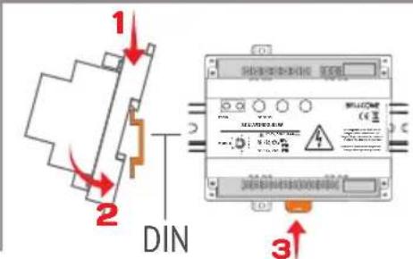

Sehen Sie Kap. 4 + 6.2 für Sicherheitsanweisungen und Beschreib Magificant il cap. 4+6.2 per istruzioni di sicurezza e descrizione See ch. 4 + 6.2 for safety instructions and description Zie hfdst. 4 + 6.2 voor veriligeidsinstrumenties en beschrijving Voir Chap. 4 + 6.2 pour des consignes de sécurité et description Sprawdzic Rozdz. 4 + 6.2 dla instrukcji bezpieczentwa i opisu
5.5.2


6.1. Safety instructions during use

DO NOT HIT the products with hard objects.
PROTECT THE PRODUCTS against lime and dust during renovation.
6.2. Significance of the acoustic signals / use of the keys
| [ BEEP ] | Short confirmation beep with a high tone. |
| 2 x [ BEEP ] | Sequence of 2 short beeps with a high tone for confirmation. |
| [ BEEP ] | Long confirmation beep with a high tone. |
| [ BEEP ] | Long error beep with a low tone. |
| Call tone in the terminal (VTA) | 5 settable ringtones. When called, the terminal plays the selected ringtone. |
| Call tone in the panel (VPA) | Each touch of ⋆ is signaled with a ding-dong. |
| Access tone in the terminal (VTA) | When access is granted, the terminal plays a confirmation tone. |
| Access tone in the panel (VPA) | When access is granted, the panel emits a sequence of beeps for confirmation. |
| Doorbell tone in the terminal (VTA) | Dedicated preset doorbell tone (if a doorbell is connected to the terminal). |
| Short touch of a key | Max. 1 sec. Every touch is confirmed with 1 x [BEEP]. |
| Long press of 1 or 2 keys simultaneously | More than 2 sec. It is confirmed with 1 x [ BEEP ]. |
6.3. The features of the central unit (SCU)


*programming button PROG. *This button is used only if you add additional terminals or TAGs to the system. red LED of PROG. (programming mode or defect within the system)
TIME: Lock timing adjustment
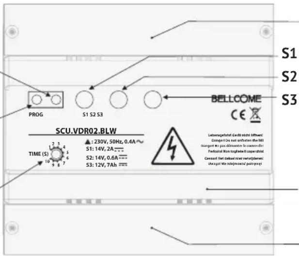
Protection lid 1 for electrical connections
S1: GREEN +14V GND (+14V/2Ad.c.)
S2: GREEN +Uv - GNV (+14V/0.5Ad.c)
S3: GREEN/RED Battery status
Front lid
Protection lid 2 for connections
Significance of LEDs signaling on SCU
| BUTTON PROG | LED PROG | LED S1 | LED S2 | LED S3 | |
| — | — | — | — | — | The system is not connected to the 230 Va.c./50 Hz network. |
| — | — | GREEN GREEN | — | The system is OK, connected to the 230 Va.c./50 Hz network. | |
| Long press | RED | GREEN GREEN | — | Programming mode (The kit is already programmed.) | |
When a battery is connected to SCU, there are the following additional signals only for S3 LED:
| — | — | — | — | GREEN | The system is not connected to the 230 Va.c./50 Hz network. The battery is functional.The system works only on audio and door opening, for a limited time slot. |
| — | — | GREEN | GREEN | GREEN | The system is OK, connected to the 230 Va.c./50 Hz network. The battery is functional. |
| RED | The system is OK, connected to the 230 Va.c./50 Hz network. Battery charging or defect. |
For LEDs signaling RED, see ch. 7 - Troubleshooting.
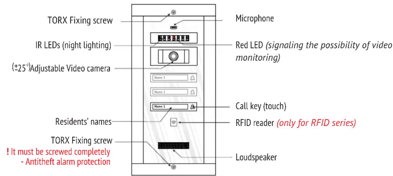
6.4. Use of the outdoor panel (VPA)
6.4.1 Functioning
| STAND-BY | The call keys and the residents' names are permanently backlit. The RED LED is blinking. |
| CALL | Short touch of ⋆ → Acoustical signaling with a ding-dong. Each touch of the key reactivates the call. |
| END CALL | After 1 min. since the last call. |
| TALK | The resident answers → Hands-free conversation, without touching any key. The talk duration is max. 2 min. |
| ACCESS being granted | The lock is open for the set temporization on SCU (between 1 and 10 sec.). The panel emits a sequence of beeps for confirmation. |
Only for Outdoor panel with RFID
| ACCESS with TAG (RFID access) | The ☑ symbol indicates the RFID tag reading area. The tags are already memorized. When used, the locks opens, the panel emits a sequence of beeps for confirmation and the ☑ symbol blinks green. |
6.4.2 Programming the panel address
The panel is already programmed with address 1, which is mandatory for the correct functioning of the system. The programming is necessary only if:
- The address 1 is changed by mistake during installation.
- Additional panels are installed. The system allows up to 3 additional panels (each with a SCU) and each of them must be programmed from its own SCU with a different address - 2, 3 or 4.
| Step 1 | Central unit SCU | PROG | Long press of PROG.→The red LED turns on. |
| Step 2 | Outdoor panel VPA | Long press of △→[ ]. The panel goes in programming. - For panel address 1 - 1 short touch of △→ 1 x [ ] →Step 3. - For panel address 2 - 2 short touches of △→ 2 x [ ] →Step 3. - For panel address 3 - 3 short touches of △→ 3 x [ ] →Step 3. - For panel address 4 - 4 short touches of △→ 4 x [ ] →Step 3. | |
| Step 3 | Central unit SCU | PROG | Press PROG.→The red LED turns off. |
Any error during programming is signaled with [ ] The procedure must be repeated from Step 2.
6.4.3 Programming additional access tags (panel with RFID only)
| Step 1 | Central unit SCU | PROG | Long press of PROG. → The red LED turns on. |
| Step 2 | Outdoor panel VPA | → | Touch with the tags, piece by piece, the symbol. After each memorized tag → [BEEEEP]. |
| Step 3 | Central unit SCU | PROG | Press PROG. → The red LED turns off. |
Any error during programming is signaled with [BEEEEP]. The procedure must be repeated from Step 2.
6.4.4 Deleting all the programmed tags (panel with RFID only)
Use this procedure only if you lost one or more of your tags. The remaining ones must be programmed again.
| Step 1 | Central unit SCU | PROG | Long press of PROG. → The red LED turns on. |
| Step 2 | Outdoor panel VPA | Lum3 Lum2 Lum1 | Long press of ∠→ [BEEEEP].The Panel goes in programming. - 7 short touches of ∠→ 2 x []. - Immediately one long press of ∠→ [].The tags are deleted. |
| Step 3 | Central unit SCU | PROG | Press PROG. → The red LED turns off. |
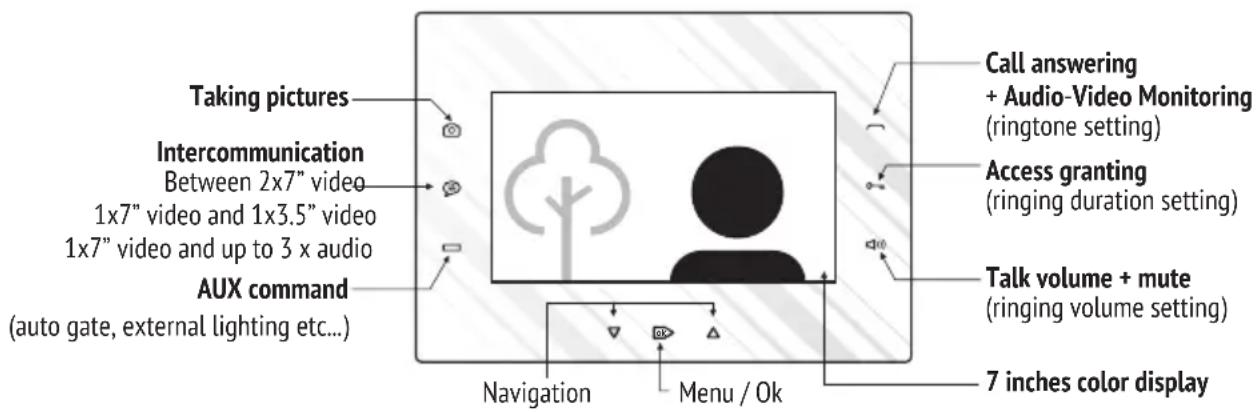
6.5. Use of the video terminal (VTA)
The factory standard settings are the following:
| Ringtone | Ding-dong (first in the list) |
| Ringing duration | 2 calls |
| Ringing volume | Level 7 from 7 |
6.5.1 Functioning
| STAND-BY | The keyboard is off. | |
| CALL | When called from the outdoor panel, the terminal rings, the key blinks white and the video image of the visitor is displayed. | |
| CALL from the doorbell | The terminal rings with the specific doorbell ringtone. | |
| RINGING VOLUME ADJUSTMENT Terminal during call | Successive short touches of .The maximum level is signaled with 2 x [ ] .With the next touch, the volume restarts from level 1. This adjustment won't be memorized, the set level has priority. | |
| RINGER OFF (MUTE) Terminal in stand-by or during call | Step 1 | Long press of → [ ] and LED turning red. The terminal has the ringer off and the LED remains red. The call will be signaled by blinking white and video image. |
| Step 2 | For reversing MUTE status, short touch → [ ] and LED turning white. | |
| Short touch of → Talk is initiated.ANSWERING THE CALL | ||
| TALK | Hands-free conversation, without touching any key. The talk duration is max. 2 min. | |
| TALK VOLUME ADJUSTMENT Terminal during talk | Successive short touches of → Increasing the talk volume in 7 levels. The maximum level is signaled with 2 x [ ] . With the next touch, the volume restarts from level 1. | |
| END TALK without access | Another short touch of . | |
| ACCESS GRANTING Terminal in stand-by or during call, talk or monitoring | From stand-by → Long press of0→. During call, talk or monitoring→ Short touch of0→ any time. The access is signaled acoustically also, with a specific confirmation song and the bidirectional audio communication remains opened 10 more sec. | |
| PICTURES TAKING Terminal during call, talk or monitoring | Implicitly, for each call from the outdoor panel one picture is taken. For deliberate picture taking, short touch of0→ any time during call, talk or monitoring. | |
| VIEW PICTURES / DELETE PICTURES Terminal in stand-by | Short touch ofok→ Entering in the Menu. Another 4 x short touches ofok→ Pictures menu. Use ∇/△ to navigate through Pictures view or Delete all. Use ok→ to select the option. In Pictures view, use√/△ to navigate. In Delete all, another touch ofok→ delete all the memorized pictures. * The memory has 100 pictures capacity and when it becomes full the new pictures replace the oldest ones. | |
| VIDEO & AUDIO MONITORING Terminal in stand-by | Short touch of→ Video and bidirectional talk for max. 10 sec. * Each short touch of changes the video camera (in case of additional cameras in the system). | |
| AUX COMMAND Terminal in stand-by or during call, talk or monitoring | From stand-by→ Long press of. During call, talk or monitoring Short touch of any time. The command is signaled acoustically also, with a specific confirmation song. | |
| INTERCOMMUNICATION Terminal in stand-by | Short touch of→ All the other terminals connected in parallel ring. The key (7") or the key (3.5" or audio) blinks white. For answering, short touch of(7") or (3.5" or audio) The intercommunication starts between the initiator terminal and the one of which were answered, for max. 1 min. For ending the intercommunication, another short touch of on . * The intercommunication cannot be initiated from the 3.5" video or audio terminals connected in parallel, it can only be received. | |
6.5.2 Settings and adjustments
You can change any standard settings of the terminal by the following procedures:
| VIDEO IMAGE ADJUSTMENT Terminal in stand-by | Step 1 | Short touch of ok → Entering in the Menu. Another 2 x short touches of bk → Display settings. Use ▽/△ to navigate through Brightness, Chroma and Contrast. Use ok to select the parameter and/△ to adjust the value. |
| Step 2 | Exit | |
| TIME & DATA SETTING Terminal in stand-by | Step 1 | Short touch of ok → Entering in the Menu. Another 3 x short touches of bk → Time & Data settings. Use ▽/△ to navigate. Use ok to select the parameter and/△ to adjust the value. |
| Step 2 | Exit | |
| Step 1 | Simultaneous long press of 0 and BEEEP → [ ]. The terminal goes in setting mode. You have 2 min. to set all the 3 features, in whatever order you choose. We suggest the following sequence. | |
| Step 2 | For setting the RINGTONE, short touches of : 1stshort touch of → The terminal plays the 1st ringtone. 2ndshort touch of → The terminal plays the 2nd ringtone. 3rdshort touch of → The terminal plays the 3rd ringtone and so on up to all 5 ringtones available. The last played ringtone remains set if is not touched again for 3 sec. | |
| CALL SETTINGS: Terminal in stand-by | For setting the RINGING DURATION, short touches of : 1stBEEPshort touch of → 1 x [ ] = the terminal will ring once with the selected ringtone. 2ndBEEPshort touch of 0→2 x [ ] = the terminal will ring twice with the selected ringtone. 3rdBEEPshort touch of 0→3 x [ ] = the terminal will ring 3 times with the selected ringtone. 4thBEEPshort touch of 0→1 x [ ] = the terminal will ring for 1 min. with the selected ringtone. The last configuration remains set if is not touched again for 3 sec. | |
| 1. RINGTONE | ||
| 2. RINGING DURATION | ||
| 3.RINGING VOLUME | ||
| (for both call from the outdoor panel and intercommunication) | ||
| Step 3 | ||
| Step 4 | For setting the RINGING VOLUME, short touches of → Each volume level, from 1 to 7, is signaled with increased intensity of the selected ringtone. The maximum level is signaled with 2 x [ ]. With the next touch, the volume restarts from level 1. The last configuration remains set if is not touched again for 3 sec. | |
| Step 5 | Touch any of the keys to quit the setting mode. Or, it will automatically quit after 7 sec. since the last operation. | |
6.5.3 Programming the terminal address
The terminals addresses are already programmed with address 1(VTA1), address 2 (VTA2) and address 3 (VTA3), which is mandatory for the correct functioning of the system.
The programming is necessary if the addresses are changed by mistake during installation. Any additional terminal connected in parallel must have the same address as the main terminal.
| Step 1 | Central unit SCU | PROG | Long press of PROG. →The red LED turns on. |
| Step 2 | Terminal VTA | Long press of [ ] . The terminal goes in programming. For terminal address 1 - 1 short touch of [ ] . For terminal address 2 - 2 short touches of [ ] . For terminal address 3 - 3 short touches of [ ] . | |
| Step 3 | Central unit SCU | PROG | Press PROG. →The red LED turns off. |
Any error during programming is signaled with [BEEEEP]. The procedure must be repeated from Step 2.
EN TROUBLESHOOTING
| No. | Problem | SCU signals | Possible causes Potential solutions | |
| 1. | The system doesn't work. | S1 — S2 — S3 — PROG — | The system has NO power supply from the 230 Va.c./ 50 Hz network and there is no battery connected to the SCU. | Check the power supply of SCU from the 230 Va.c./ 50 Hz network or the fuses status. Check FUSE on the entry in SCU. |
| 2. | The system works OK. | S1 green S2 green | System OK. | — |
| S3 — PROG — | No battery (max. 7 Ah) connected to the central unit (SCU). | — | ||
| S3 green | With battery (max. 7 Ah) connected to the central unit (SCU). | — | ||
| S3 red | The battery is during charging or defect. | The battery must be replaced if the S3 LED doesn't turn green after 5 hours. | ||
| 3. | The system works without video, for a limited time. | S1 — S2 — S3 green PROG — | The system has no power supply from the 230 Va.c./ 50 Hz network or the fuses are burned (the systems works only on battery, with the basic features: door opening and talk). | Check the power supply of SCU from the 230 Va.c./ 50 Hz network or the fuses status. Check FUSE on the entry in SCU. |
| 4. | The system doesn't work. | S1 red S2 red or green S3 — PROG — | Short circuit between +14V and GND and/or GNV and +Uv. | Check the connections between +14V and GND and/or GNV and +Uv. Correct any errors. |
| 5. | The system works OK, but the voltages measured to the VTA connectors are lower than 11 Vd.c. +14 V - GND < 11 V +Uv - GND < 11 V (ch. 5.5) | S1 green S2 green S3 — PROG — | Only 1 wire connected on +14V and GND terminals, instead of 2 wires, as shown in the connection diagram. | The 2nd wire must be connected to +14V or GND, as shown in the connection diagram. |
| The cable length in the system is higher than 150 m. | We recommend the installation of a video amplifier (DVA) before or after SCU. An additional cable of 3 x 0,75 mm² is required. | |||
| The installation was made with a different cable from the one recommended, with a higher resistance - >8 Ω/100m. | ||||
| 6. | The call from the outdoor panel (VPA) doesn't function. Uc=0V or 5V (ch. 5.5) | S1 green S2 green S3 — PROG blinking red | The CD connection could be: - incorrectly connected or in short circuit with +14V, +Uv, GND or GNV - interrupted or not connected to VPA, (VCB), SCU or VTA. | Check CD everywhere in the system and correct any errors. |
| VPA is not programmed with address 1. | Program VPA with address 1, see the procedure (ch. 6.4.2.). If additional panels are installed, they must be programmed with different address - 2, 3 or 4. | |||
| 7. | The terminal (VTA) doesn't ring when called from the outdoor panel (VPA). | S1 green S2 green S3 — PROG — | The CD connection may be interrupted between SCU, (VCB) and VTA. | Check CD connection of SCU, (VCB) and VTA and the continuity of the wire. Correct any errors. |
| VTA is not programmed with the correct address. | Program VTA with the correct address, see the procedure (ch. 6.5.3.). | |||
| The terminal (VTA) doesn't signal with [ ] when the keyboard is touched. | Check +14, GND connections of SCU, (VCB) and VTA and the continuity of the wire. Correct any errors. | |||
| 8. | There is a disturbing noise during talk on the terminal (VTA). The other features are OK. | S1 green S2 green S3 PROG— | The GND connections are not OK (not tight enough). | Check the GND connections of VPA, (VCB), SCU and VTA. Firmly tighten the wires in the connector. |
| The cable used has more wires than UTP cat5e (AWG24), which is recommended for installation. | The wires remained free, including the shield wire, will be connected only to the GND connector of SCU (2 wires in GND). | |||
| 9. | The video display of the terminal (VTA) is Black (off) during call and talk. | S1 green S2 red S3 PROG— | Short circuit between +Uv and GNV and/ or GND. | Check the connections +Uv and GNV/ GND and correct any errors. |
| 10. | The video display of the terminal (VTA) is Blue during call and talk. | S1 green S2 green S3 PROG— | No video signal. | The Vin/ Vout or GNV connection is interrupted in one connector (VPA,SCU, (VCB) or VTA). Check and correct any errors. |
| The video camera is defect. VPA must be replaced. | ||||
| The connections Vin/ Vout or GNV are reversed somewhere in the system or in short circuit. | Check Vin/ Vout and GNV everywhere in the system and correct any errors. | |||
| 11. | The COLOR video image of the terminal (VTA) is blurred all the time. | S1 green S2 green S3 PROG— | High attenuation on the cable between VPA and VTA: - Cable length higher than 150 m - The cable used is different from the one recommended (not twisted and/ or with higher resistance). | Remove VTA from the wall, but keep it connected to the system. With a PH 0 screwdriver trimmer adjusts the impedance trimmer (2) from the back until you get a better image. |
| 12. | The video image of the terminal (VTA) is BLACK & WHITE. | S1 green S2 green S3 PROG— | The cable length in the system is higher than 150 m. | We recommend the installation of a video amplifier (DVA) before or after SCU in order to amplify the attenuated video signal and increase the voltage on +14V and +Uv connections. |

MAINTENANCE
EN
The outdoor panels must be kept away from corrosive substances, paints or mechanical shocks. The terminals must be kept away from water, or any other liquids, mechanical shocks, fumes, dusts etc. The components of the system can be cleaned with a piece of soft, cotton cloth.
The optional battery connected with the central unit will be replaced after the expiry of its life span. The central unit ensures the battery's charging, as long as the battery is not defect. The state of the battery is indicated by the signals of the LED S3 in RED / GREEN.

WARRANTY
EN
A three year warranty is granted, from the purchase date, on the basis of the proof of purchase and if the system was used according to the technical manual.

NO WARRANTY IS GRANTED for: inappropriate installation and use, deliberate damaging, theft, fire, natural disasters, unauthorized interventions to the system, the lack of protection of the system's components in case of renovation activities in the building. The warranty does not include the access TAGs as they are considered consumable goods.
The BELLCOME systems for residential buildings are produced in compliance with the EU standards and bear the CE conformity marking. 39