F16C Fighting Falcon - Remote control toy FMS - Free user manual and instructions
Find the device manual for free F16C Fighting Falcon FMS in PDF.

| Product type | Radio-controlled technical hobby aircraft (RC toy category) |
| Brand | FMS |
| Model | F16C Fighting Falcon 70 mm |
| Wingspan | 813 mm (32 in) |
| Overall length | 1258 mm (49.5 in) |
| Flight-ready weight | Approximately 2090 g (73.8 oz) |
| Wing loading | 102.5 g/dm² (0.23 oz/sq.in) |
| Wing area | 20.4 dm² (316.2 sq.in) |
| Power system | Brushless inrunner motor 2860-Kv1850 and 70mm 12-blade V2 fan |
| Speed controller (ESC) | Brushless 70A Predator with safe start |
| Servos | 6 digital 9g metal gear servos |
| Recommended battery | LiPo 6S 22.2V 3300mAh 35C (not included) |
| Radio system | 4+ channel transmitter (not included, receiver not included) |
| Material | EPO foam (expanded polyolefin) |
| Key features | Aerobatic flight, electric retractable landing gear, LED lights, 5 sets of customizable decals |
| Center of gravity (CG) | 95 to 105 mm behind the wing's leading edge |
| Recommended age | 14 years and older (adult supervision required) |
| Maintenance | Clean with a soft cloth, store dry out of reach of children, check screws before each flight |
| Spare parts | Available (part numbers FMSRF101 to FMSRF121, motor, ESC, servos, etc.) |
| Kit contents | Fuselage, wings, stabilizers, vertical fin, ventral fins, nose cone, missiles, wing tube, linkages, hardware, decals |
| Warranty | Contact retailer or FMS |
Frequently Asked Questions - F16C Fighting Falcon FMS
User questions about F16C Fighting Falcon FMS
0 question about this device. Answer the ones you know or ask your own.
Ask a new question about this device
Download the instructions for your Remote control toy in PDF format for free! Find your manual F16C Fighting Falcon - FMS and take your electronic device back in hand. On this page are published all the documents necessary for the use of your device. F16C Fighting Falcon by FMS.
USER MANUAL F16C Fighting Falcon FMS
WARNING: Read the ENTIRE instruction manual to become familiar with the features of the product before operating. Failure to operate the product correctly can result in damage to the product, personal property and cause serious injury.
This is a sophisticated hobby product and NOT a toy. It must be operated with caution and common sense and failure to do so could result in injury or damage to the product or other property. This product is not intended for use by children without direct adult supervision.
This manual contains instructions for safety operation and maintenance. It is essential to read and follow all the instructions and warnings in the manual prior to assembly, setup or use, in order to operate and avoid damage or serious injury.
Safety Precautions and Warnings
As the user of this product, you are solely responsible for operating in a manner that does not endanger yourself and others or result in damage to the product or the property of others. This model is controlled by a radio signal subject to interference from many sources outside your control. This interference can cause momentary loss of control so it is advisable to always keep a safe distance in all directions around your model, as this margin will help avoid collisions or injury.
Age Recommendation: Not for children under 14 years. This is not a toy.
·Never operate your model with low transmitter batteries.
·Always operate your model in an open area away from cars, traffic or people.
·Avoid operating your model in the street where injury or damage can occur.
·Never operate the model in populated areas for any reason.
·Carefully follow the directions and warnings for this and any optional support equipment you use (chargers,rechargeable battery packs, etc.)
- Keep all chemicals, small parts and anything electrical out of the reach of children.
- Moisture causes damage to electronics. Avoid water exposure to all equipment not specifically designed and protected for this purpose.
·Never lick or any place of any your model in your mouth as it could cause serious injury or even death.
Safety
Lithium Polymer (Li-Po) Battery Warning
CAUTION: Always follow the manufacturer's instructions for safe use and disposal of batteries. Fire, property damage, or serious injury can result from the mishandling of Li-Po batteries.
By handling, charging or using a Li-Po Battery you assume all risks associated with lithium batteries. If at any time the batteries begin to swell or balloon, discontinue use immediately!
Always store the batteries at room temperature in a dry area to extend the life of the battery. Always transport or temporarily store the battery in a temperature range of 40-120F. Do not store the battery or model in a car or in direct sunlight. If stored in a hot car, the battery can be damaged or even catch fire.
Never use a Ni-Mh Charger to charge Li-Po Batteries. Failure to charge the battery with a Li-Po compatible charger may cause fire resulting in personal injury and property damage.
▶ Never discharge Li-Po Cells below 3V.
▶ Never leave charging batteries unattended.
▶ Never charge damaged batteries.
Charging the Flight Battery Warning
Use a battery charger that is designed to safely charge the Li-Po Battery. Read the charger instructions care fully before use. When charging the battery, make certain the battery is on a heat resistant surface. It is also highly recommended to place the Li-Po Battery inside a fire resistant charging bag readily available at hobby shops or online.
Introductions
The remarkable USAF F-16C Fighting Falcon is known as the most capable single engine supersonic multirole fighter aircraft in the world. It is also one of the most prolific fighters in service in the USAF. It is a true American marvel!
FMS would like to announce the release of a fully upgraded 70mm F-16C! Following the success of the 64 mm F16 V2, the enhanced F-16C 70 mm is sure to impress!
This new version features a more detailed scale look, boosted aerobatic performance and the famous FMS user friendly assembly design.
The FMS 70 mm F-16C adopts a scale USAF camouflage. With five different decals and pin-up sticker set ups, you build and customize you own plane.
In addition to looks and its streamlined aerodynamic shape, the new F-16C is equipped with strengthened retractable landing gears, that ensure a smoother takeoff and landing experience for all pilots.
Get ready to experience real combat maneuvers with the new F-16! With a 70 mm 12-blade ducted fan, powerful KV1850 inner running motor and predator 70A ESC, the F-16 boasts extraordinary performance and thrust!
What are you waiting for? Add the new FMS 70 MM F-16C Fighting Falcon to your hanger!
• High quality Predator 70A ESC, powerful KV1850 inner running motor with the latest 70mm 12-blade EDF.
- Rich details, clean lines.
- Button type canopy hatch.
- Pre-installed, newly designed ball link style control horns for more throw.
- A set of 5 different decals so you can customize yourself.
Contents of Kit
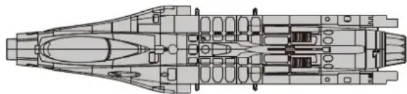
Before assembly, please inspect the contents of the kit. The photo below details the contents of the kit with labels. If any parts are missing or defective, please identify the name or part number (refer to the spare parts list near the end of the manual) then contact your local shop or email us: support @fmsmodel.com.
Specifications
Wingspan: 813mm(32in)
Overall Length: 1258mm(49.5in)
Flying Weight: Around 2090g(73.8oz)
Motor Size: Brushless 2860-KV1850
Wing Load: 102.5 g/dm²(0.23oz/in²)
Wing Area: 20.4 dm²(316.2sq.in)
ESC: 70A
Servo: 9g Servo x 6
Recommended Battery: 22.2V 3300mAh 35C
Table of Contents
Introduction 3
Contents of Kit 3
Model Assembly 4
Battery installation 7
Connectors Diagram ....
Get your model ready to fly 7
Clevis Installation ....
Control Horn and Servo Arm Settings 9
Center of Gravity(CG) 9
Before flying the model 10
Flying Course 10
Troubleshooting 11
Spare parts list content 11
Decal Instruction 12
A.
natural_image
Technical line drawing of a mechanical assembly (no text or symbols)B.
C.
D.
FE. G.


l.

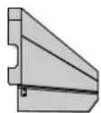
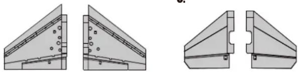
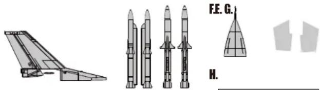
A: Fuselage
B: Main Wing Set
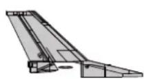
C: Horizontal Stabilizer
D: Vertical Stabilizer
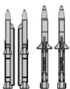
E: Missile Set
F: Nose Cone
G: Ventral Fin
H: Wing Tube
I: Linkage Rods and Screws
Model Assembly
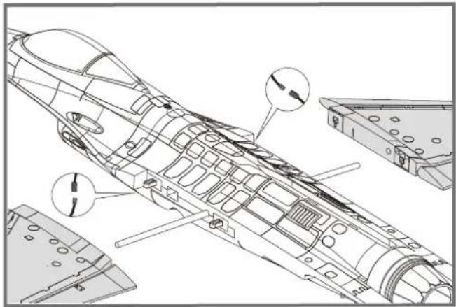
Main Wing Installation
- Slide the tube into the fuselage then install both wings over the wing tube and into the wing slot of the fuselage.
Notice: The connectors on both side should be attached precisely and firmly.
natural_image
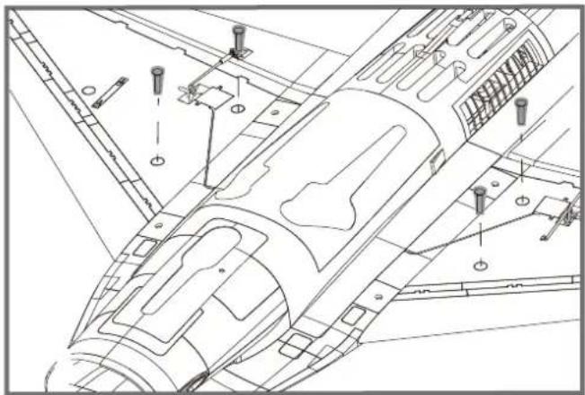
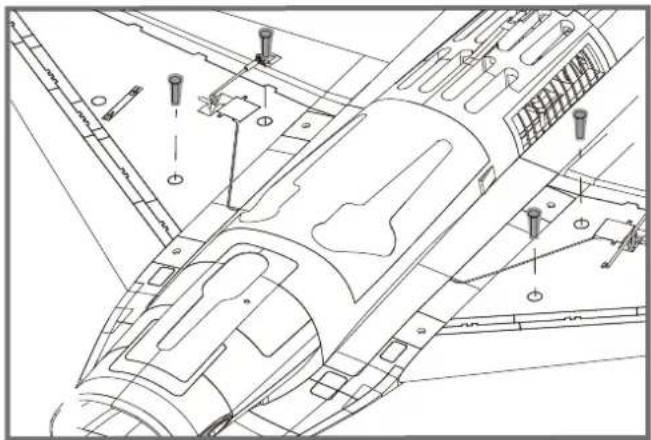
Technical line drawing of an aircraft fuselage with internal components and structural details (no text or symbols)- Secure the wings on the fuselage using the included screws as shown.
natural_image
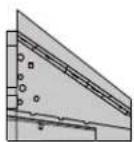
Technical line drawing of a mechanical assembly with bolted components and mounting holes (no text or labels)Horizontal Stabilizer Installation
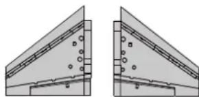
- With the bottom of the fuselage facing up, carefully apply CA to the base and the side of the rear fuselage slot. Install the stabilizer into the place. Ensure the control horn faces down as shown.

natural_image
Technical line drawing of an aircraft fuselage assembly (no text or symbols)Model Assembly
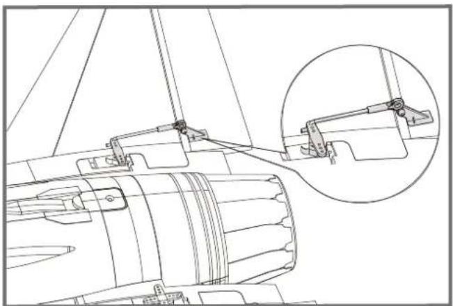
- Attach the ball link to the elevator control horn's outermost hole using the included linkage rod as shown.
natural_image
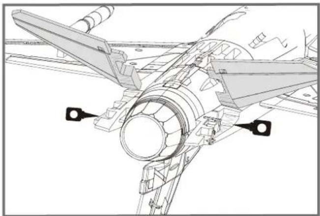
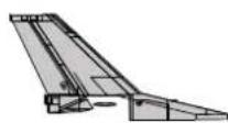
Technical line drawing of a mechanical assembly with an inset close-up showing a bracket detail (no text or symbols)Vertical Stabilizer Installation
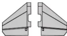
- Carefully apply CA to the top rear fuselage slot. Install the vertical stabilizer into place.
Notice: The connectors on both side should be attached precisely and firmly.

natural_image
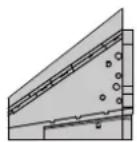
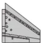
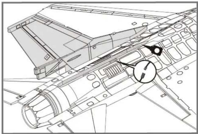
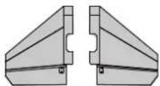
Technical line drawing of an aircraft fuselage with structural components and a circular annotation (no text or symbols)Ventral Fin Installation
- Carefully apply CA to the bottom rear fuselage slot. Install the ventral fins into place.
Note: 1. Ensure the higher side goes towards the front of the plane. 2. The fins will angle towards the outboard of the plane as shown.

natural_image
Architectural line drawing of a modern building complex with curved architecture and a magnified inset showing a detail (no text or symbols)Model Assembly
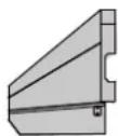
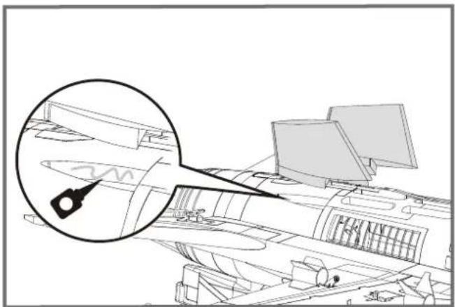
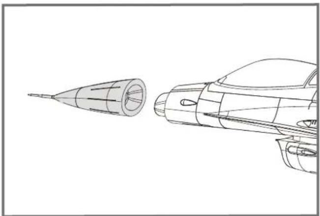
Nose Cone Installation
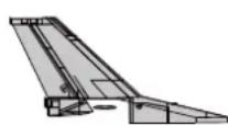
- Apply the nose cone to the front fuselage as shown. Ensure the nose cone is on the correct side
natural_image
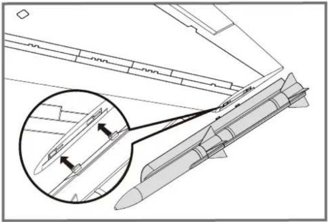
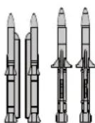
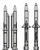
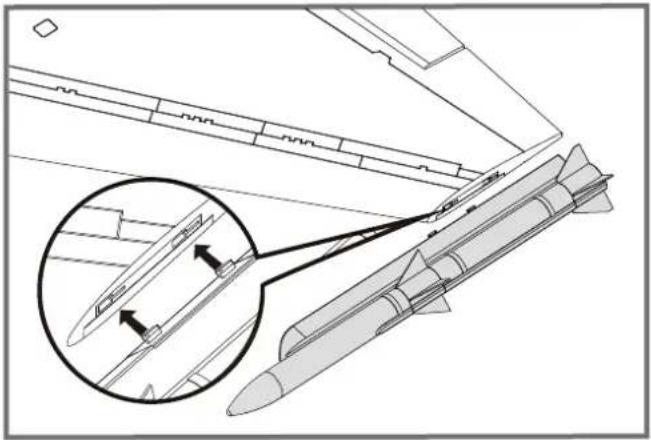
Line drawing of a rocket engine and its side profile, showing internal components (no text or symbols)Missile Set Installation
1.Slide the missiles into the rails as shown.
natural_image
Technical line drawing of a missile with an inset magnified detail showing internal components (no text or symbols)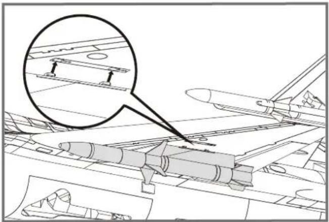
natural_image
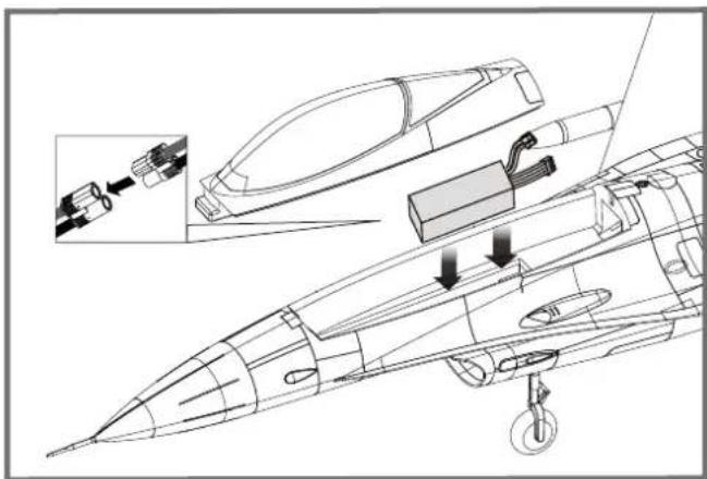
Technical line drawing of an aircraft carrier deck with a magnified inset showing structural components (no text or symbols)Battery installation
- Apply the hook tape to the cable end of the battery.
- Slide the battery into the battery hatch with the power supply cable toward the rear end of the plane and the hook tape facing the bottom of the battery hatch.
Note: You may need to relocate the battery position to achieve the correct CG for your model.
natural_image
Technical line drawing of a jet engine internal components, showing exploded view and assembly (no text or labels)Connectors Diagram
Attach aileron servo to the aileron channel of your receiver. Elevator harness goes to elevatorchannel of your receiver. Steering servo goes to the rudder channel. Attach the ESC connector to the throttle channel of the receiver. The LED to any spare channel. Tuck the wire leads into the recessed cavity at the rear end of the battery hatch.
| Receiver | ||
| Aileron | 1 | Channel-1— Aile |
| Elevator | 2 | Channel-2— Elev |
| Throttle | 3 | Channel-3— Thro |
| Rudder | 4 | Channel-4— Rudd |
| Gear | 5 | Channel-5— Gear |
| spare | Spare Channel | |
Get your model ready to fly
Important ESC and model information
- The ESC included with the model has a safe start. If the motor battery is connected to the ESC and the throttle stick is not in the low throttle or off position, the motor will not start until the throttle stick is moved to the low throttle or off position. Once the throttle stick is moved to the low throttle or off position, the motor will emit a series of beeps. Several beeps with the same tune means the ESC has detected the cells of the battery. The count of the beeps equals the cells of the battery. The motor is now armed and will start when the throttle is moved.
- The motor and ESC come pre-connected and the motor rotation should be correct. If for any reason the motor is rotating in the wrong direction, simply reverse two of the three motor wires to change the direction of rotation.
- The motor has an optional brake setting. The ESC comes with brake switched off and we recommend that the model be flown with the brake off. However, the brake could be accidentally switched on if the motor battery is connected to the ESC while the throttle stick is set at full throttle. To switch the brake off, move the throttle stick to full throttle and plug in the motor battery. The motor will beep one time. Move the throttle stick to low throttle or the off position. The motor is ready to run and the brake will be switched off.
- Battery Selection and Installation. We recommend the 22.2v 3300mAh 35C Li-Po battery. If using another battery, the battery must be at least a 22.2v 3300mAh 35C battery. Your battery should be approximately the same capacity, dimension and weight as the 22.2v 3300mAh 35C Li-Po battery to fit the fuselage without changing the center of gravity significantly.
The transmitter and model setup
Before getting started, bind your receiver with your transmitter. Please refer to your Transmitter Manual for proper operation. CAUTION: To prevent personal injury, DO NOT install the propeller assembly onto the motor shaft while testing the control surfaces. DO NOT arm the ESC and do not turn on the transmitter until the Transmitter Manual instructs you to do so. Tips: Make sure all control sticks on your radio are in the neutral position (rudder, elevator, ailerons) and the throttle is in the OFF position. Make sure both ailerons move up and down (travel) the same amount. This model tracks well when the left and right ailerons travel the same amount in response to the control stick.
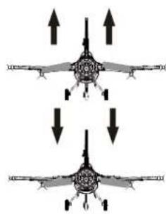
Move the controls on the transmitter to make sure the aircraft control surface moves correctly. See diagrams right.
Bank Left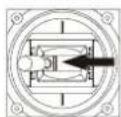 [300T1 [300T1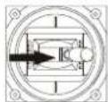 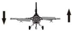 Bank Right Bank Right | Aileron |
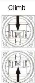  Descend Descend | Elevator |
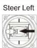 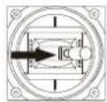 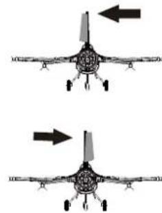 Steer Right Steer Right | Steering Rudder |
Check the control throws
The suggested control throw setting for FMS MODEL are as follows (dual rate setting):
Tips: On first flight, fly the model in low rate. The first time you use high rates, be sure to fly at low to medium speeds. High rate, as listed, is only for EXTREME maneuvering.
| High Rate | Low Rate | |
| Elevator | 12mm up/down | 10mm up/down |
| Aileron | 14mm up/down | 10mm up/down |
| Rudder | 16mm left/right | 12mm left/right |
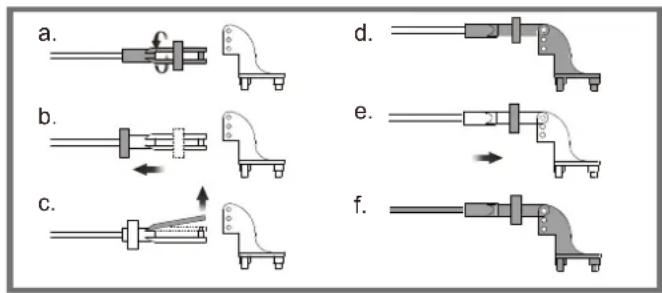
Clevis Installation
- Pull the tube from the clevis to the linkage.
- Carefully spread the clevis, then insert the clevis pin into the desired hole in the control horn.
- Move the tube to hold the clevis on the control horn.
Control Horn and Servo Arm Settings
The table shows the factory settings for the control horns and servo arms. Fly the aircraft at the factory settings before making changes.
After flying, you may choose to adjust the linkage positions for the desired control response.
ElevatorRudderAile
| ElevatorRud | Horns | Arms |
| More control throw |
| Less control throw |
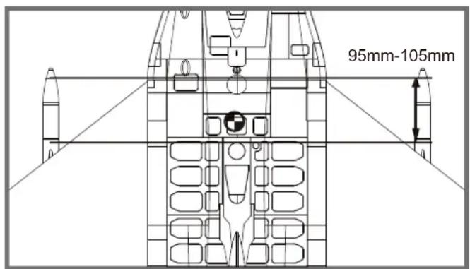
Check the C.G. (Center of Gravity)
When balancing your model, adjust the battery as necessary so the model is level or slightly nose down. This is the correct balance point for your model. After the first flights, the CG position can be adjusted for your personal preference.
-
The recommended Center of Gravity (CG) location for your model is(95-105mm) from the leading edge of the main wing (as shown) with the battery pack installed. Mark the location of the CG on top of the wing.
-
When balancing your model, support the plane at the marks made on the bottom of the main wing with your fingers or a commercially available balancing stand. This is the correct balance point for your model. Make surethe model is assembled and ready for flight before balancing.
Before flying the model
Find a suitable flying site
Find a flying site clear of buildings, trees, power lines and other obstructions. Until you know how much area will be required and have mastered flying your plane in confined spaces, choose a site which is at least the size of two to three football fields - a flying field specifically for R/C planes is best. Never fly near people - especially children, who can wander unpredictably.
Perform the range check for your plane
As a precaution, an operational ground range test should be performed before the first flight each time you go out. Performing a range test is a good way to detect problems that could cause loss of control such as low batteries, defective or damaged radio components, or radio interference. This usually requires an assistant and should be done at the actual flying site you will be using.
First turn on the transmitter, then install a fully-charged battery into the fuselage. Connect the battery and install the hatch.
Remember, use care not to bump the throttle stick. Otherwise, the propeller/fan will turn and possibly cause damage or injury.
Note: Please refer to your Transmitter Manual that came with your radio control system to perform a ground range check. If the controls are not working correctly or if anything seems wrong, do not fly the model until you correct the problem. Make certain all the servo wires are securely connected to the receiver and the transmitter batteries have a good connection.
Monitor your flight time
Monitor and limit your flight time using a timer (such as on a wristwatch or in your transmitter if available). When the batteries are getting low you will usually notice a performance drop before the ESC cuts off motor power, so when the plane starts flying slower you should land. Often (but not always) power can be briefly restored after the motor cuts off by holding the throttle stick all the way down for a few seconds. To avoid an unexpected dead-stick landing on your first flight, set your timer to a conservative 4 minutes. When your alarm sounds you should land right away.
Flying Course
Take off
While applying power, slowly steer to keep the model straight. The model should accelerate quickly. As the model gains flight speed you will want to climb at a steady and even rate. It will climb out at a nice angle of attack (AOA).
Flying
Always choose a wide-open space for flying your plane. It is ideal for you to fly at a sanctioned flying field. If you are not flying at an approved site always avoid flying near houses, trees, wires and buildings. You should also be careful to avoid flying in areas where there are many people, such as busy parks, schoolyards, or soccer fields. Consult laws and ordinances before choosing a location to fly your aircraft. After takeoff, gain some altitude. Climb to a safe height before trying technical manoeuvres, including high speed passes, inverted flight, loops, and point rolls.
Landing
Land the model when you hear the motor pulsing (LVC) or if you notice a reduction in power. If using a transmitter with a timer, set the timer so you have enough flight time to make several landing approaches.
The model's three point landing gear allows the model to land on hard surfaces. Align model directly into the wind and fly down to the ground. Fly the airplane down to the ground using 1/4-1/3 throttle to keep enough energy for proper flare. Before the model touches down, always fully decrease the throttle to avoid damaging the propeller or other components. The key to a great landing is to manage the power and elevator all the way to the ground and set down lightly on the main landing gear. After a few flights you will find the model can be set down lightly on the mains and you can hold the nose wheel off balancing themodel on the mains until it slows and gently settles the nose.
Maintenance
Repairs to the foam should be made with foam safe adhesives such as hot glue, foam safe CA, and 5min epoxy. When parts are not repairable, see the Spare Parts List for ordering by item number.
Always check to make sure all screws on the aircraft are tightened. Pay special attention to make sure the spinner is firmly in place before every flight.
Trouble shooting
| Problem Possible Cause Solution | ||
| Aircraft will not respond to the throttlebut responds to other controls. | -ESC is not armed.-Throttle channel is reversed. | -Lower throttle stick and throttle trim to lowest settings.-Reverse throttle channel on transmitter. |
| Extra propeller noise or extravibration. | -Damaged spinner,propeller,motor or motor mount.-Loose propeller and spinner parts.-Propellor installed backwards. | -Replace damaged parts.-Tighten parts for propeller adapter,propeller and spinner.-Remove and install propeller correctly. |
| Reduced flight time or aircraft underpowered. | -Flight battery charge is low.-propeller installed backward.-Flight battery damaged. | -Completely recharge flight battery.-Replace flight battery and follow flight battery instructions. |
| Control surface does not move,or is slow to respond to control inputs. | -Control surface,control horn, linkage or servo damage.-Wire damaged or connections loose. | -Replace or repair damaged parts and adjust controls.-Do a check of connections for loose wiring. |
| Controls reversed. | Channels are reversed in the transmitter. | Do the Control Direction Test and adjust controls for aircraft and transmitter. |
| -Motor loses power-Motor power pulses then motor loses power. | -Damage to motor,or battery.-Loss of power to aircraft.-ESC uses default soft Low Voltage Cutoff(LVC). | -Do a check of batteries,transmitter,receiver,ESC,motor and wiring for damage(replace as needed).-Land aircraft immediately and recharge flight battery. |
| LED on receiver flashes slowly. | Power loss to receiver. | -Check connection from ESC to receiver.-Check servos for damage.-Check linkages for binding. |
Spare parts list content
| FMSRF101 | Fuselage | FMSRF116 | Landing Gear Cover |
| FMSRF102 | Main Wing Set | FMSRF117 | Linkage Rod |
| FMSRF103 | Vertical Stabilizer | FMSRF118 | Pipe |
| FMSRF104 | Horizontal Stabilizer | FMSRF119 | Screw |
| FMSRF105 | Missle-1 | FMSRF120 | Wheel Set |
| FMSRF106 | Missle-2 | FMSRF121 | Decal Sheet |
| FMSRF107 | Cockpit | FMSRE039 | EL Retract |
| FMSRF108 | Cowl | FMSDF12B70 | 70mm Ducted fan |
| FMSRF109 | Ventral Fin | PRKV1850 | 2860-KV1850 |
| FMSRF110 | Front Landing Gear Set (Steel) | PRESC019 | 70A ESC |
| FMSRF111 | Front Landing Gear Set (CNC Metal) | (With 400mm length input cable) | |
| FMSRF112 | Main Landing Gear Set | FMSSER9MGDP | 9g digital metal gear servo positive |
| FMSRF113 | Front Landing Gear System (Steel) | FMSSER9MGDR | 9g digital metal gear servo reverse |
| FMSRF114 | Front Landing Gear System (CNC Metal) | ||
| FMSRF115 | Main Landing Gear System |
Visit our website to see photos of this product: www.fmsmodel.com
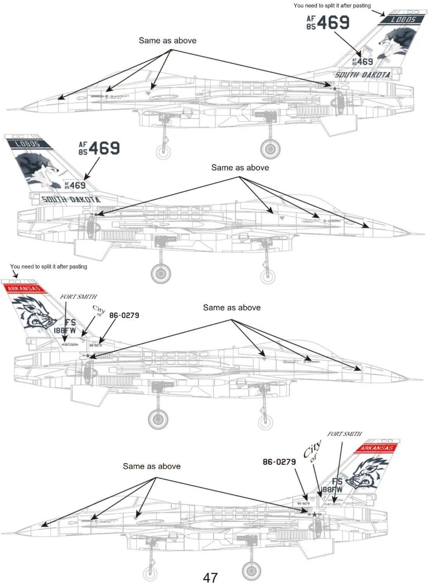
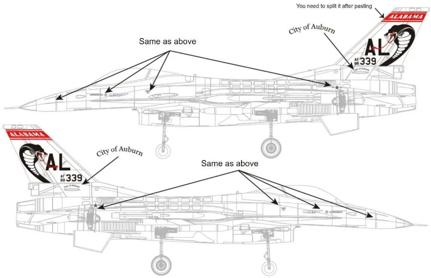
Decal Instruction
Please choose one set of the decals according to your taste or history materials and paste it as shown (for reference only).

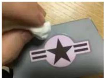
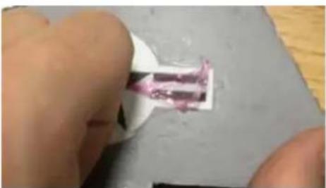
Water Decal Instructions:
The above are water decals. Do not force them off from the backing paper. Please operate according to the following steps:
- Make sure your hands are dry, and cut the decal down with scissors carefully.
- Put the decal in water for 2 mins to bring it to full absorption.
- Carefully remove the decal from the backing paper and apply it on the corresponding position of the airframe (it would be helpful to wet the corresponding position of the airframe to adjust the decal)
- Soak up the excess water with tissue, squeeze out air slowly, and wait for drying.
Note: Remove the thin film (over the decals)24 hours later.
natural_image
Hand holding a white object over a gray square with a star and three horizontal stripes (no text or symbols visible)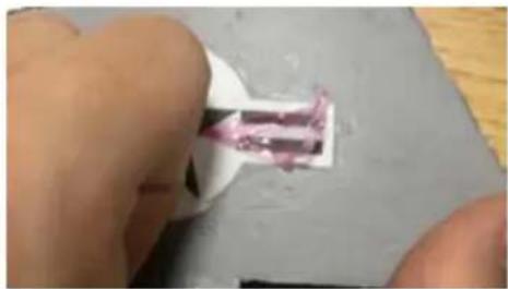
natural_image
Close-up of a hand holding a small object with pink markings, possibly a tool or component (no visible text or symbols)Warnhinweise

natural_image
Technical line drawing of a mechanical assembly (no text or symbols)B.
natural_image
Technical drawings of three views of a mechanical bracket assembly (no text or symbols)D.
natural_image
Technical line drawings of missile systems including a flat support structure and three variants of missiles, with no visible text or symbols.l.

natural_image
Technical line drawing of a mechanical assembly with labeled components (no text or symbols present)natural_image
Technical line drawing of a mechanical assembly with bolted components and mounting holes (no text or labels)natural_image
Technical line drawing of an aircraft fuselage assembly (no text or symbols)Montage des Modells
natural_image
Technical line drawing of a mechanical assembly with a magnified inset showing a detail (no text or symbols)natural_image
Technical line drawing of a mechanical assembly with no visible text or symbolsMontage der Finnen
natural_image
Architectural line drawing of a modern building with curved roof and window (no text or symbols)Montage des Modells
Anstecken der Nase
natural_image
Technical line drawing of a rocket engine and its side profile, showing internal components (no text or symbols)Montage der Raketen
natural_image
Technical line drawing of a missile with an inset magnified detail showing internal components (no text or symbols)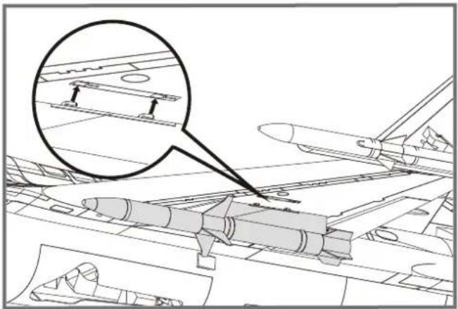
natural_image
Technical line drawing of an aircraft carrier deck with a magnified inset showing structural components (no text or symbols)natural_image
Technical line drawing of a jet aircraft showing internal components and structural details (no text or symbols)Vor dem Erstflug

natural_image
Close-up of a hand holding a white plastic object with a pink substance inside, placed on a gray surface (no text or symbols visible)ATTENTION

natural_image
Technical line drawing of a mechanical assembly (no text or symbols)B.
natural_image
Technical diagram showing two views of a structural component with bolt holes and mounting brackets (no text or symbols)C.
D.
FE. G.


l.

G : Quilles ventrales
natural_image
Technical line drawing of a mechanical assembly with internal components and cross-sections (no text or symbols)natural_image
Technical line drawing of a mechanical assembly with bolted components and mounting holes (no text or labels)natural_image
Technical line drawing of an aircraft fuselage assembly (no text or symbols)
Montage du modèle
natural_image
Technical line drawing of a mechanical assembly with an inset magnified detail (no text or symbols)natural_image
Technical line drawing of an aircraft fuselage with structural components and a circular component (no text or symbols)
natural_image
Architectural line drawing of a modern building complex with a magnified inset showing a detail of a mechanical component (no text or symbols)Montage du modèle
natural_image
Technical line drawing of a rocket engine and its side profile (no text or symbols)natural_image
Technical line drawing of a missile with an inset magnified detail showing internal components (no text or symbols)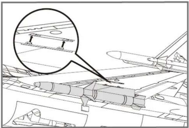
natural_image
Technical line drawing of an aircraft carrier deck with a magnified inset showing structural components (no text or symbols)natural_image
Technical line drawing of a jet engine internal components, showing structural assembly and component insertion (no text or labels)natural_image
Hand holding a white object over a gray surface with a star and three horizontal stripes (no text or symbols visible)
natural_image
Close-up of a hand holding a small white object with a pink substance, placed on a gray surface (no text or symbols visible)警告

natural_image
Technical line drawing of a mechanical assembly (no text or symbols visible)B.
C.
D.
F.E.G.


1.

A:机身
B:主翼
C:平尾
D:垂尾
natural_image
Technical line drawing of a mechanical assembly with internal components and mounting features (no text or symbols)- 使用所附螺丝固定机翼。
natural_image
Technical line drawing of an aircraft fuselage with structural components and mounting points (no text or labels)平尾安装
natural_image
Technical line drawing of an aircraft fuselage assembly (no text or symbols)机体安装
natural_image
Technical line drawing of a mechanical assembly with an inset magnified detail (no text or symbols)垂尾安装
natural_image
Technical line drawing of an aircraft fuselage with structural components and a circular component (no text or symbols)腹鳍安装
natural_image
Architectural line drawing of a modern building complex with a magnified inset showing a detail of a mechanical component (no text or symbols)机体安装
机头罩安装
natural_image
Technical line drawing of a rocket engine and its side profile, showing internal components (no text or symbols)导弹安装
- 将导弹一一锁进相对应的槽位。
natural_image
Technical line drawing of a missile with an inset magnified detail showing internal components (no text or symbols)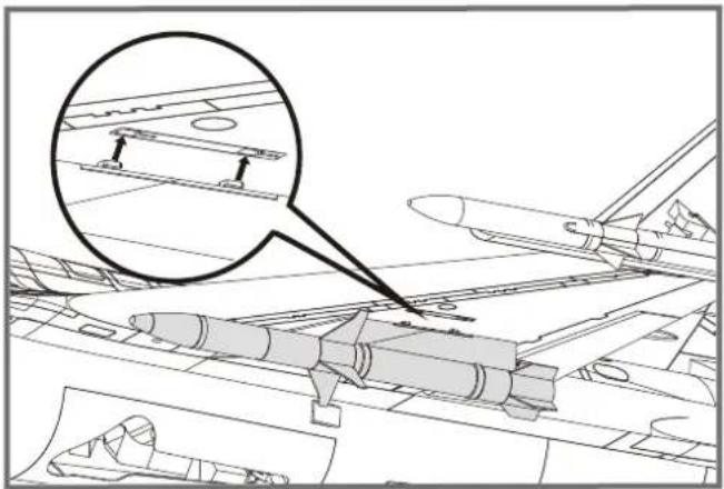
natural_image
Technical line drawing of an aircraft carrier deck with a magnified inset showing structural components (no text or symbols)电池安装
natural_image
Technical line drawing of a jet engine internal components, showing structural assembly and component insertion (no text or labels)接收机连接示意图
飞行前准备
起飞前的检查
natural_image
Close-up of a hand holding a white object with a pink, curved substance inside, against a gray surface (no text or symbols visible)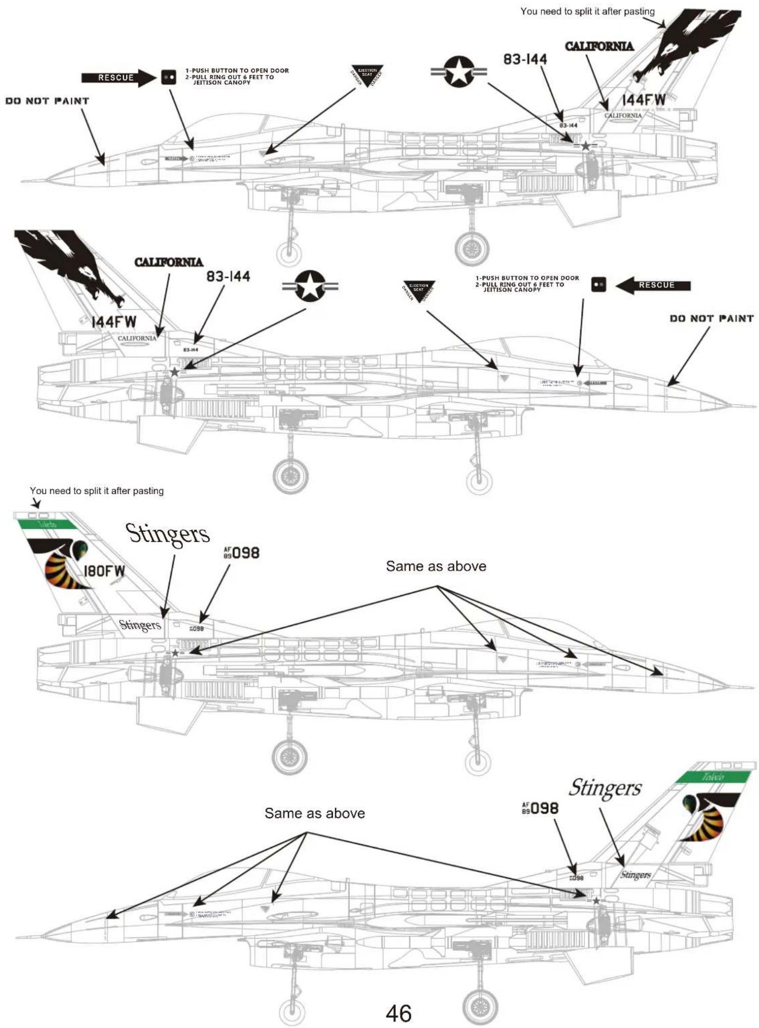
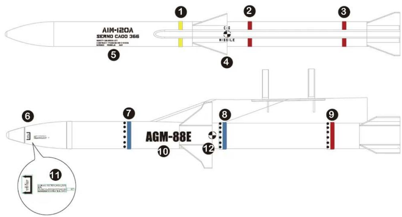
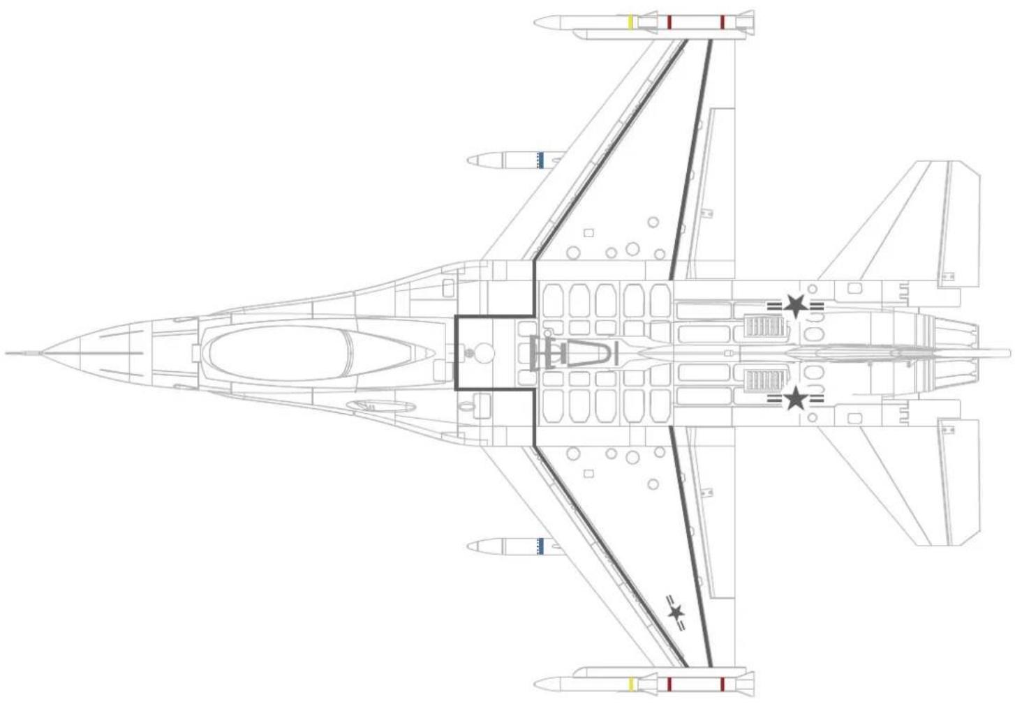
The below adhesive decals are for airframe and missiles. Apply them as shown.

natural_image
Abstract green line drawing with horizontal bars and rectangular extensions (no text or symbols)1

2

3

4

MISSILE
5
AIM-120A
SERNO CAOO 366
82577·3819500-107
CONTRACT F08635-89-C-0036
60IDED MISSILE AAV
6
7

natural_image
Simple diagram of black dots aligned horizontally on a light blue and white background (no text or symbols)8

natural_image
Simple diagram with a row of black dots on a white horizontal bar and a blue base (no text or symbols)9

natural_image
A red and white striped background with evenly spaced black dots (no text or symbols)10

GUIANCE SECTION.WGU-2B/B S/N PN 96214-30003ASSY74AS1900 SET WARRANTY EXPIRATION DATE
11

12
natural_image
Top-down technical line drawing of a fighter jet cockpit with visible internal compartments and star insignia (no text or symbols)