VDV920 - Intercom ME - Free user manual and instructions
Find the device manual for free VDV920 ME in PDF.
| Product type | Video intercom |
| Brand | ME |
| Model | VDV920 |
| Dimensions of outdoor station (without lens) | 160 x 233 x 3 mm (W x H x D) |
| Dimensions of flush-mounted box | 133 x 210 x 35 mm (W x H x D) |
| Operating voltage | 15 V DC |
| Current consumption | 130 ± 50 mA |
| Camera detection angle | 135° horizontal / 100° vertical |
| Temperature range | -10°C to +50°C |
| Electric strike connection | 12 V DC, max 1 A |
| Number of doorbells | 2 (two-apartment house) |
| Required cables | 8 cables from outdoor station to indoor + 2 for the strike |
| Outdoor volume adjustment | Potentiometer |
| Adjustable strike opening duration | 1 or 5 seconds |
| Adjustable ID code | Via DIP switch (ID1 to ID3) |
| Cover material | Brushed stainless steel |
| Steel maintenance | Clean with special stainless steel detergent, in the direction of the grain |
| Warranty | 2 years |
| Safety | Installation by a specialist, disconnect before cleaning, do not dismantle |
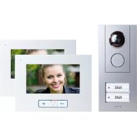
| Main functions | Audio/video communication, doorbell, door opening, external camera connection |
Frequently Asked Questions - VDV920 ME
User questions about VDV920 ME
0 question about this device. Answer the ones you know or ask your own.
Ask a new question about this device
Download the instructions for your Intercom in PDF format for free! Find your manual VDV920 - ME and take your electronic device back in hand. On this page are published all the documents necessary for the use of your device. VDV920 by ME.
USER MANUAL VDV920 ME
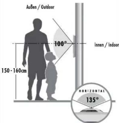
ILLUSTRATION 3
AFBEELDING 3
text_image
Außen / Outdoor 100° Innen / Indoor 150 - 160cm HORIZONTAL 135°EINLEITUNG
Thank you for choosing the VISTADOOR video intercom system. You have purchased a high quality system with a stainless steel cover. The elaborate stainless steel covers are made by hand and thus have individual characteristics that should be considered a sign of quality.

Notes on caring for stainless steel
Please never clean the stainless steel surfaces with standard cleaning materials, as these are too harsh. Please simply clean using spray designed for the cleaning and care of stainless steel. If this is not available please use only clear water.
Brushed surfaces should always be cleaned with the grain and never in a circular motion. This will avoid the creation of scratches.
Failure to observe these notes may lead to discolouration or even to rust damage in extreme cases.

The system should be assembled by a specialist.
Key
- Camera
- Loudspeaker perforations
- Bell button
- Microphone
4.1. Connection for microphone - Casing screws
- Lightness sensor
- Volume potentiometer
- Dip switch for the opening time of the door opener
- Dip switch for the ID code
- Connection terminal door opener
- Connection terminal power supply
- Connection terminal signal line
- Connection terminal external camera
- Installation aid
- Outdoor unit
15.1. Stainless steel front plate
15.2. Inner housing
15.3. Wall box

PREPARATION FOR INSTALLATION
The following lines are required:
Single-family house (VDV-910): 4 lines from the outdoor unit to the indoor unit and 2 lines from the outdoor unit to the door opener.
Duplex house (VDV-920): 4 lines per bell push-button from the outside unit to each apartment are required here, i.e. you need 8 lines from the outside station to the inside (4 each per family 1 and 2) and 2 lines for the door opener.
Up to four indoor units can be connected in parallel per residential unit. The connection can either be laid from the indoor station or in a star formation from a central point (distribution box).
The lines should be laid in such a way that they are fed out of the wall directly behind the relevant outdoor/indoor unit.
Note: It is also possible to combine video and audio components with the VISTADOOR system.
INSTALLATION OF THE OUTDOOR STATION
The intercom system is designed to be flush-mounted.

Preparation
When removing the front cover, take care that the indicator field and the nameplate do not fall out and get damaged.
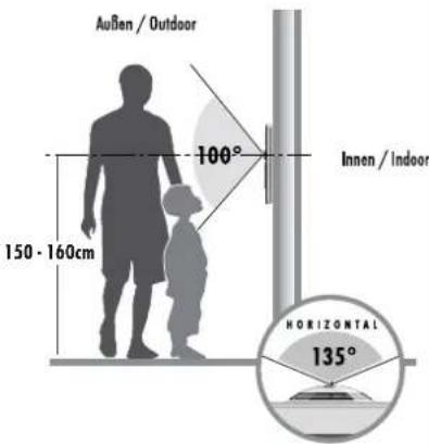
The camera should be mounted at a height of approx. 1.5-1.6m (middle of the camera) (Fig. 3). Before installing the intercom system, test whether the camera captures a sufficient image of the visitor. If necessary, adjust the installation height and location to suit the local conditions.
- Remove the four screws in the stainless steel front plate using a Torx key (T10) and then lift this carefully upwards. Make sure you do not tear off the microphone cable. You can now reveal the flush mounted shell by removing the outdoor station.
- Hold the wall box straight on the wall and draw around it on the wall with a suitable pencil. Take care that the necessary connecting cables are in the middle part of the wall box. The cables should not be measured too short.
- The cable feedthrough can be detached with a sharp knife.

Note:
The hole for the intercom system should be measured so that the wall box fits precisely inside and is flush with the building wall.
- In order to anchor the wall box to the wall, first use the holes in the base of the wall box to mark the 8 fixing holes in the wall and then drill corresponding holes (diameter approx. 6 mm).
- Next place the supplied dowels in the holes. The wall box can now be affixed with the 4 outer screws. Take care here to ensure that the wall box is level; check this if necessary with a spirit level. The wall box must also not be twisted.

NOTE: If the wall box is affixed only insecurely by the screws, the wooden frame can be filled along the sides with appropriate glue.
- For plastering insert the supplied plaster aid into the wall box. This prevents the wall box from being filled with mortar / plaster. When plastering make sure that the threaded inserts will not be soiled with mortar / plaster.
- Insert the outer unit into the wall box. In order to prevent the outer unit from falling out, use the supplied installation aid (14). It is easily screwed to the wall box using one of the Torx screws and holds the outer unit in position.
- Remove the cover over the screw terminals on the outer unit and feed the cable through the relevant inlet.
- Now connect the cable to the intercom system. (See Point CONNECTION)
Fit the name plate
The nameplate consists of two transparent plastic parts, which are joined together with 2 respectively 4 small screws.
- Remove both screws on the nameplate and take it apart; the foil for inscription is between the plastic parts.
- Write on the foil with a smear-resistant felt pen or print a name-plate inlay* using a PC and a printer.
- Place the written nameplate inlay between the two plastic parts and screw these back together.

*Size of the nameplate:
VDV 910: 71 mm x 34 mm
VDV 920: 71 mm x 15 mm
- In order to be able to replace the front cover on the outdoor station first insert the nameplates into the outdoor station and fix them on the sides using the supplied tape strips so that they cannot fall out. Alternatively you many also fix the nameplates with transparent sticky tape.
- Remove the assembly aid and secure the outdoor station from falling with your hand. A second person can help.
- Replace the microphone plug into the circuit board and replace the front cover on the outdoor station. Take care not to crush the microphone cable.
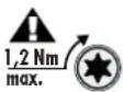
- Screw on the front cover with the relevant 4 Torx screws. Please ensure that the screws are not tilted or over-tightened. The maximum tightening torque is 1.2 Nm. This value must not be exceeded as the threads in the flush mounted shell can otherwise become unusable or fall out.

Note: Self-adhesive foam is supplied to seal the front plate against water. It is affixed to the edge of the front plate from behind.
CONNECTION
Connect the laid line to Audio 1, +15V, GND and Video 1 (figure 2) on the outdoor station and connect it with the indoor station/s. These are also present on the indoor station and need only be connected with one another 1:1.
Note on the duplex house version: one 4-pole connection terminal is provided per residential unit; the connector terminals are numbered. Terminal 1 is for the lowest bell button, terminal 2 for the bell button above it.
Connecting a door opener
The door opener is connected directly to the outdoor station by two lines (figure 2.2, no. 12). No additional power supply is necessary to control the door opener. The door opener must be designed for 12 V direct current and may not require more than 1 A current. The two connector terminals are marked 'Doorlock' and 'GND' if the door opener needs to be poled. 'GND' is negative.
Connecting the power supply
The power supply can either be connected to the indoor or to the outdoor station. Separate screw terminals exist for this purpose (figure 2). It is also possible to connect the power supply directly to the signal line, e.g. if all signal lines have been laid from the fuse box to the outdoor and indoor units. The power supply unit then needs to be connected with earth (GND) and +15V.
Up to 8 units can be supplied with power from one power supply unit. A second power supply unit is required if there are more than eight units, e.g. if 2 outdoor and 7 indoor stations need to be used.
The second power supply unit can simply be switched parallel to the
first power supply unit.
The second power supply unit should be connected with a short line to the indoor or outdoor station that is farthest away so that any drop in current in the connection line can be compensated.
Connecting an external camera
An external camera can be connected to this screw terminal (figure 2) in order, for example, to provide additional monitoring of areas that cannot be seen by the main camera. All cameras can be connected that require operating voltage of 12 V DC and supply an FBAS video signal. The video line is connected to the terminal (VIDEO IN) and the earth line to the terminal (GND), operating voltage for the camera is taken from the terminals '+12V DC OUT' (positive pole) and 'GND' (negative pole).
The external camera automatically has the ID 4
(see chapter on ID code).
No sound transmission is possible when the external camera is active.
When using the VDV 500 XCam, the X-module is not needed.
POSSIBLE SETTINGS
The outdoor station offers the following possibilities to set the system to your personal circumstances:
Volume of the outdoor station
The potentiometer (7) is used to set the volume on the outdoor station. To set the highest volume, turn the potentiometer carefully clockwise as far as possible. Reduce the volume by turning in an anti-clockwise direction.
ID code
If several outdoor stations are switched in parallel (e.g. at the gate entrance and the house) then the ID code is set via the dip switch (9). This makes it possible to activate the individual outdoor units in sequence, e.g. in order to monitor the coverage of the relevant outdoor unit. The switch is carried out on the indoor station with the 'monitor' switch.
ID1 = Switch 1 'on' Switch 2 'on'
ID2 = Switch 1 'on' Switch 2 'off'
ID3 = Switch 1 'off' Switch 2 'on'
Opening time of the door opener
The DIP switch (8) is used to set the time the door opener remains activated. The options are either 1 second or 5. The factory setting is 5 seconds, which works for most conventional door openers.
Switch to the left to "5S" for 5 seconds open time.
Switch to the right to "1S" for 1 second open time.
OPERATION
- Press the bell push-button.
- The preset ring tone sounds on its inside station/s and the screen displays the outside station view.
- Accept the dialogue on the inside unit by briefly pressing the press-to-talk button (MOUTH).
- If an additional camera is present at the outside station, you may switch over to this camera by pressing the "MONITOR" button.

Pressing the „Monitor“ button again switches you back to the internal camera.

- If a door opener is connected then you can activate the door opener by pressing briefly on the door opener button (KEY).

- Switch the system back to standby operation by briefly pressing the speak button (MOUTH).
TECHNICAL DATA
Operating voltage: 15 V DC
Current consumption: 130 ± 50 mA
Camera detection angle: 135^ horizontal / 100^ vertical
Temperature range: -10°C to +50°C
Dimensions (w x h x d): 160 x 233 x 3 mm (without lens)
Wall box (w x h x d): 133 x 210 x 35 mm
Door opener connection: DC 12V, max. 1A
INFORMATION
Information regarding CE - Conformity
The functionality of the unit can be affected by the influence of strong static, electrical or high frequency fields (discharging, mobile phones, radios, microwaves).
Cleaning and maintenance
Always disconnect mains powered units from the mains supply before cleaning (disconnect the plug). The unit housing can be cleaned using a soapy soft cloth. Do not use any abrasive materials or chemicals.
Remove dust build-up from ventilation slits using a brush and clean up using a vacuum cleaner. Do not hold the vacuum cleaner nozzle directly against the unit.
Safety instruction
In the event of damage to the housing, connectors, power cables or isolation shielding, switch off the device immediately and disconnect from the mains power. ELECTRIC SHOCK - DANGER OF
LOSS OF LIFE. (Unplug the mains connector from the socket!).
Damage should be repaired immediately by a specialist!


Never carry out repairs yourself!
Warranty
2 years warranty from date of purchasing, on base of correct using.
The producer is not responsible for consequential damages which are effected directly or indirectly from this item.
SAFETY NOTES
The warranty will be null and void in case of damages arising from violations of these operating instructions. We are not liable for consequential damages!
We accept no liability for material damages or injuries arising from inappropriate use or violation of the safety instructions. In such cases all warranty claims are null and void!
For reasons of safety and licensing (CE), unauthorised conversion and / or modification of the product is prohibited.
The design of the product complies with protection class 1. Only a standard mains socket (230V\~/50Hz) of the public mains supply may be used to power the device. Devices powered by mains voltage must be kept away from children. Please therefore be particularly careful in the presence of children.

Do not take the product apart! There is a danger of lethal electric shock!
Do not leave packaging material lying about since plastic foils and pockets and polystyrene parts etc. could be lethal toys for children.
The interior units are suitable only for dry interior rooms (not bathrooms and other moist places). Do not allow the devices to get moist or wet. There is a danger of lethal electric shock!
Please consult a specialist should you have doubts regarding the method of operation, the safety, or the connections of the device.
Handle the product with care - it is sensitive to bumps, knocks or falls even from low heights.
GB
These operating instruction are published by m-e GmbH modern-electronics,
The operating instructions reflect the current technical specifications at time of print. We reserve the right to change the technical or physical specifications.
INTRODUCTION
Ajuster la plaque nominative
text_image
① ② ③ ④.1 ⑥ 15.2 15.3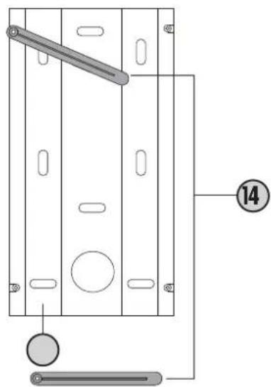
natural_image
Technical diagram of a mechanical device with labeled components and connection lines (no readable text or symbols)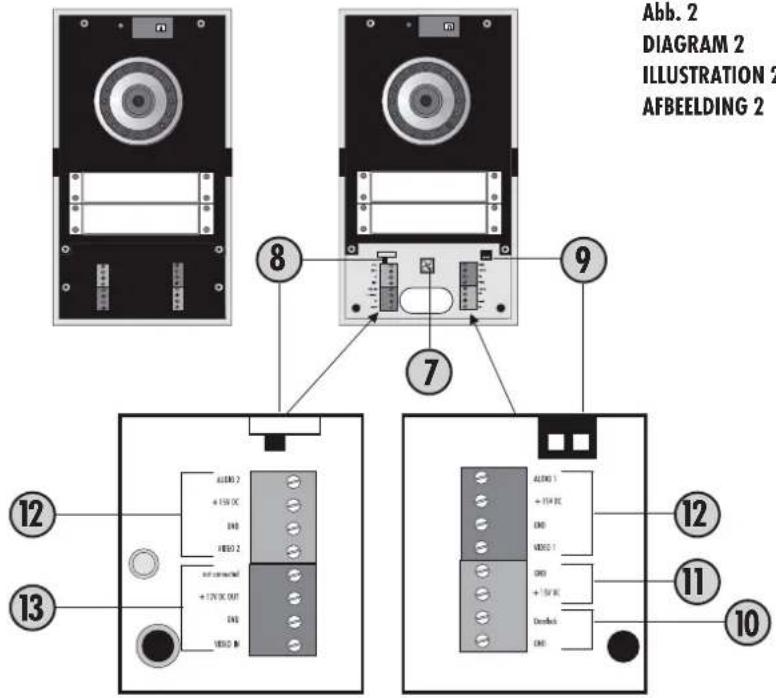
text_image
Abb. 2 DIAGRAM 2 ILLUSTRATION 2 AFBEELDING 2 8 9 7 12 13 12 11 10Abb. 2
Abb. 3
DIAGRAM 3
ILLUSTRATION 3
AFBEELDING 3
text_image
Außen / Outdoor 100° Innen / Indoor 150 - 160cm HORIZONTAL 135°
SYSTEM