
OMC 1000 M - Fireplace EWT - Free user manual and instructions
Find the device manual for free OMC 1000 M EWT in PDF.
| Product type | Flame effect fireplace |
| Brand | EWT |
| Model | OMC 1000 M |
| Supply voltage | 240 V ~ 50 Hz (13 A) |
| Main functions | Adjustable flame effect (height and intensity), adjustable crackling effect (volume), remote control, manual controls and receiver |
| Water supply | Water tank (manual filling) or connection to mains water (pressure 0.5 to 8 bar) |
| Control types | Button panel under the fuel bed (6 buttons per side), receiver with 6 buttons, wireless remote control |
| Flame effect | Starts after 45 seconds, maximum height for 5 seconds then nominal adjustment |
| Material | Not specified (metal, plastic) |
| Maintenance and cleaning | Clean tray, water tank, cap, air filter every 2 weeks; use only filtered tap water; do not use distilled water |
| Safety | Do not cover, minimum distance of 1 m from combustible materials, do not use outdoors, do not place under a wall socket, disconnect before cleaning |
| Spare parts and repairability | Replaceable transducer (consumable); other parts: contact customer service |
| Warranty | 1 year from purchase date (excluding transducer discs) |
| Recycling | Do not dispose of with household waste; use local recycling services |
| General information | Flame effect unit only; biocide treatment (Silver Biocide) of tray and tank; do not drink water from tray; minimum ventilation required: 420 cm² |
Frequently Asked Questions - OMC 1000 M EWT
User questions about OMC 1000 M EWT
0 question about this device. Answer the ones you know or ask your own.
Ask a new question about this device
Download the instructions for your Fireplace in PDF format for free! Find your manual OMC 1000 M - EWT and take your electronic device back in hand. On this page are published all the documents necessary for the use of your device. OMC 1000 M by EWT.
USER MANUAL OMC 1000 M EWT
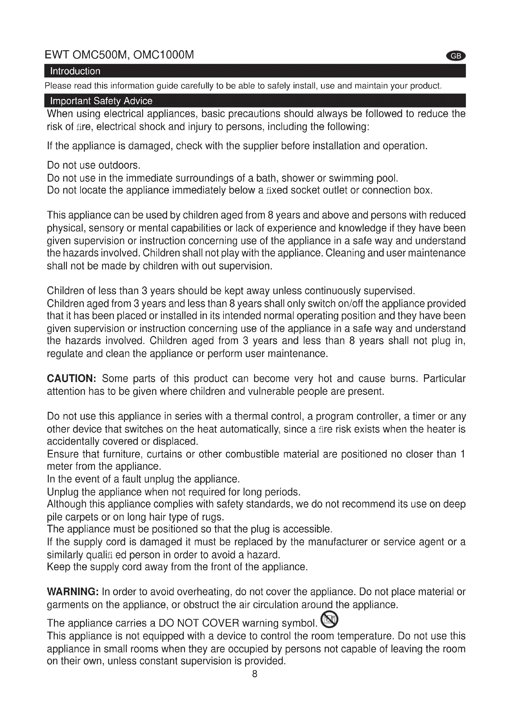
natural_image
Technical line drawing of a rectangular electronic device with mounting feet and a flat top panel (no text or symbols)OMC500M
natural_image
Technical line drawing of a rectangular mechanical or electronic component with mounting feet and mounting holes (no text or symbols)OMC1000M

DE 1
GB 8
FR 14
IT 21
Einführung
Please read this information guide carefully to be able to safely install, use and maintain your product.
Important Safety Advice
When using electrical appliances, basic precautions should always be followed to reduce the risk of fire, electrical shock and injury to persons, including the following:
If the appliance is damaged, check with the supplier before installation and operation.
Do not use outdoors.
Do not use in the immediate surroundings of a bath, shower or swimming pool.
Do not locate the appliance immediately below a fixed socket outlet or connection box.
This appliance can be used by children aged from 8 years and above and persons with reduced physical, sensory or mental capabilities or lack of experience and knowledge if they have been given supervision or instruction concerning use of the appliance in a safe way and understand the hazards involved. Children shall not play with the appliance. Cleaning and user maintenance shall not be made by children with out supervision.
Children of less than 3 years should be kept away unless continuously supervised.
Children aged from 3 years and less than 8 years shall only switch on/off the appliance provided that it has been placed or installed in its intended normal operating position and they have been given supervision or instruction concerning use of the appliance in a safe way and understand the hazards involved. Children aged from 3 years and less than 8 years shall not plug in, regulate and clean the appliance or perform user maintenance.
CAUTION: Some parts of this product can become very hot and cause burns. Particular attention has to be given where children and vulnerable people are present.
Do not use this appliance in series with a thermal control, a program controller, a timer or any other device that switches on the heat automatically, since a fire risk exists when the heater is accidentally covered or displaced.
Ensure that furniture, curtains or other combustible material are positioned no closer than 1 meter from the appliance.
In the event of a fault unplug the appliance.
Unplug the appliance when not required for long periods.
Although this appliance complies with safety standards, we do not recommend its use on deep pile carpets or on long hair type of rugs.
The appliance must be positioned so that the plug is accessible.
If the supply cord is damaged it must be replaced by the manufacturer or service agent or a similarly qualified person in order to avoid a hazard.
Keep the supply cord away from the front of the appliance.
WARNING: In order to avoid overheating, do not cover the appliance. Do not place material or garments on the appliance, or obstruct the air circulation around the appliance.
The appliance carries a DO NOT COVER warning symbol.

This appliance is not equipped with a device to control the room temperature. Do not use this appliance in small rooms when they are occupied by persons not capable of leaving the room on their own, unless constant supervision is provided.
General Information
Only use fi Itered water in this appliance.
Unpack the appliance carefully and retain the packaging for possible future use, in the event of moving or returning the fire to your supplier.
Always ensure that the appliance is sitting on a level surface.
The appliance is a fl ame effect only.
The appliance is designed to be built into a surround or built into a wall.
Before connecting the appliance, check that the supply voltage is the same as that stated on the appliance.
Please note: Used in an environment where background noise is very low, it may be possible to hear a sound which is related to the operation of the flame effect. This is normal and should not be a cause for concern.
Once installed, never move this appliance or lay on its back, without draining the water from sump and water tank.
The water tank, sump, sump lid, tank cap and air filters must be cleaned once every two weeks, particularly in hard water areas.
If you intend not using the appliance for longer than 2 weeks, drain the water from sump and water tank and dry the sump.
The sump and the water tank in this product are treated with a biocidal product, Silver Biocide. This conforms with the latest relevant ISO standard
Do not drink the water from the sump or from the water tank(s)
This appliance is intended to be permanently connected to the water mains and not connected by a hose-set
Installation Instructions
This section describes how to set up your fi re.
BEFORE YOU START
- Ensure that all packing items are removed (read any warning labels carefully) and retain all packing for possible future use.
- Before connecting the appliance, check that the supply voltage is the same as that stated on the appliance.
- Ensure that the appliance is sitting on a level surface
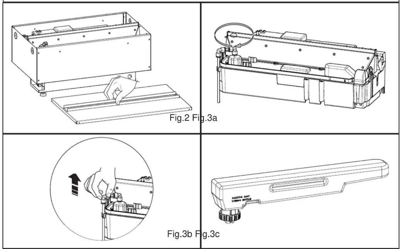
- Lift off the metal top plate to gain access to the appliance. Keep the top plate with the packing for possible future use. (Fig.2)
Installation Guide
This product can be built into a wall, surround or structure. Please take note of the product dimensions in Fig.1 and build your wall, surround or structure accordingly. You are required to leave a minimum of 400mm from the base of the fuelbed to any shelf/enclosure above the product. This will allow enough space above the product to allow the flames to form fully and not to be obstructed.
This product needs free ventilation from underneath to operate correctly. The free ventilation helps keep the electronic components cool, allow the mist to evacuate the sump and lift out of the product effortlessly.
THE AREA OF FREE VENTILATION THE OMC500M REQUIRES IS A MINIMUM OF 210CM. THE AREA OF FREE VENTILATION THE OMC1000M REQUIRES IS A MINIMUM OF 420CM.
Surround Design
The OMC500M and OMC1000M are designed to be built into a surround/wall. Using the dimensions provided in Fig1, you can design a cavity for the appliance. Be sure to allow room under and around the appliance for the water connection and the electrical connection. Once the surround/wall is prepared you can put the appliance in place. Fit the appliance so you ensure that it is centered. When you have settled on a position, lift off the Fuelbed and using appropriate screws for the surround/wall, screw through the formed holes in the left and right side panels securing the appliance in place.
Water Supply
The appliance can operate by using the water tank(s) provided or by connecting up mains water.
Water Tank(s): You will need to remove the 'Fill Cap' from the sump. (Fig.3a and Fig.3b). Place the Water Tank(s) (Fig.3C) in your sink and remove the cap (turn anti-clockwise). Fill the Water Tank with filtered tap water only. This is necessary to prolong the life of the flame and smoke producing unit. The water should be filtered through a conventional domestic water filter unit and the filter should be replaced regularly. Distilled water must not be used.
Mains Water: If you choose to supply mains water to the appliance store the bottle(s) with the metal top plate and packaging. You can use the Piercing Valve (supplied) to connect into your mains water supply by;
- Clamp the Piercing Valve onto you water pipe: maximum 1/2" (12.7mm) pipe
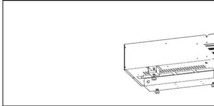
- Connect a 1/4" (6.35mm) PVC tube (not supplied) from the piercing valve into the water filter supplied and then in to the product (Fig.4).
-
Turn the tap on the valve clockwise to pierce into the water pipe. Turn the tap anti-clockwise to allow the water to flow through the valve. You can shut off the water to the product by turning the tap on the valve clockwise until the flow stops.
-
Turn on the internal ball valve. This is located under the sump. Remove the sump as described under 'Cleaning' in the Maintenance section
Please note: the water pressure is to be between 8Bar (800Kilopascals) and 0.5Bar (50Kilopascals).
If you do not feel confident making this connection please consult a qualified plumber, to ensure a safe and secure installation.
Electrical Connection
Plug the fire into a 13amp/240 volt outlet. Be sure to have access to the plug after installation to allow for disconnection. Ensure that the supply cable exits at the back of the fire, at the right or left hand corner to suit your supply socket location and is not trapped under the fire such that it might cause it to be damaged. If connecting multiple appliances into the same outlet be sure not to connect more than 5 appliances. If more appliances are required they must be connected into a separate circuit.
The appliance can be connected to the fixed wiring of the premises through a suitable connection box positioned adjacent to the appliance. This electrical installation must be carried out by a competent electrician and be in strict accordance with the current I.E.E regulations for Electrical Equipment in Buildings.
The electrical can remove the supplied plug by the following;
- Lift off the fuelbed and put switch 'A' into the off position (Fig 9).
- Ensure that the appliance is unplugged.
- Lift off the access cover by removing the retaining screw (Fig 15).
- Unscrew and remove the Live, Neutral and Earth wires.
- Unscrew the cable clamp (Fig 16 'A') and remove the supply cord.
The electrician can then connect their wire from the appliance (by following the steps above in reverse) to the connection box ensuring that it incorporates a double pole isolating switch having a contact separation of at least 3mm. Brown - Live (L), Blue - Neutral (N) and Green/Yellow - Earth (E).
Connecting the Receiver
Take your Receiver, 4button for OMC500M and 6button for OMC1000M, and with the Fuelbed removed insert the 3.5mm jack into the socket at the back of the appliance (Fig.5). The Receiver has a cable length of 1.4m which will allow you position it anywhere around the product. If you prefer to hide it the Receiver can be placed inside the surround/wall. Please ensure that the Receiver is not enclosed in metal, concrete or any other dense material, this will affect the signal from the remote control.
Operating the Product
This section describes how to activate your fire using either the manual controls or remote control.
MANUAL CONTROLS
The manual controls are located beneath the Fuelbed. (Fig.6)
OMC500M
Mains Switch 'A':- Controls the electricity supply to the appliance.
Note: This switch must be in the 'ON' (I) position for the appliance to operate
Button panel 'A':- Controls the functioning of the appliance
- ↓ is the on/standby button. Press it to turn on and off the flame effect. Turning it on will be indicated by the main lights activating. Although the main lights operate immediately it will take a further 45 seconds before the flame effect starts.
• ✝ is the Pairing button. This will pair your remote control to the receiver. See 'Remote Control Operation' for details - is the test mode button. This will be used by the manufacturer and the Service Engineer
- is the reduce flame button. Press this to reduce the height/intensity of your flame. You will hear an audible beep when you reach the minimum level
- is the increase flame button. Press this to increase the height/intensity of your flame. You will hear an audible beep when you reach the maximum level
- is the reduce fire crackling sound. Press this to reduce the volume of the crackling sound. The minimum volume for this is off
• is the increase fire crackling sound. Press this to increase the volume of the crackling sound.
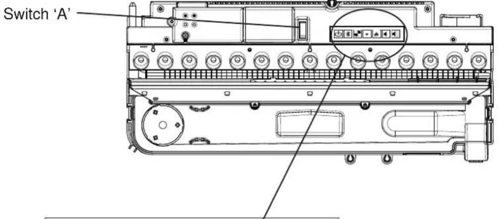
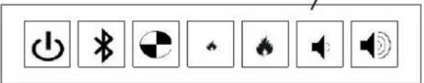
OMC1000M
Mains Switch 'A':- Controls the electricity supply to the appliance.
Note: This switch must be in the 'ON' (I) position for the appliance to operate
Button panel 'A':- Controls the functioning of the left side of appliance
- ↓ is the on/standby button. Press it to turn on and off the flame effect. Turning it on will be indicated by the light activating. Although the main lights operate immediately it will take a further 45 seconds before the flame effect starts.
• is the Pairing button. This will pair your remote control to the receiver. See 'Remote Control Operation' for details
- is the test mode button. This will be used by the manufacturer and the Service Engineer
- is the reduce flame button. Press this to reduce the height/intensity of your flame. You will hear an audible beep when you reach the minimum level
- is the increase flame button. Press this to increase the height/intensity of your flame. You will hear an audible beep when you reach the maximum level
- is the reduce fire crackling sound. Press this to reduce the volume of the crackling sound. The minimum volume for this is off
• is the increase fire crackling sound. Press this to increase the volume of the crackling sound.
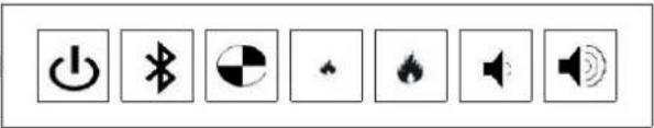
Button panel 'B':- Controls the functioning of the left side of appliance
- is the test mode button. This will be used by the manufacturer and the Service Engineer
- is the reduce flame button. Press this to reduce the height/intensity of your flame. You will hear an audible beep when you reach the minimum level
- is the increase flame button. Press this to increase the height/intensity of your flame. You will hear an audible beep when you reach the maximum level
- is the reduce fire crackling sound. Press this to reduce the volume of the crackling sound. The minimum volume for this is off
- is the increase fire crackling sound. Press this to increase the volume of the crackling sound.
GETTING THE DESIRED FLAME EFFECT
- Switch the appliance on by pressing the main switch to the on position and pressing the on/standby button. The flames will start after 45 seconds. The flames will be at max height for 5 seconds and then reduce to a nominal level
- Press the ♠ and ♦ buttons to adjust the flame to your desired level. Please give the flame generator time to react to the changes you make.
- Do not tilt or move the appliance while there is water in the tank or sump
- Make sure that the appliance is on a level surface
Once you have made you adjustments to both the flame height and crackling sound the appliance will keep these settings even if you power off the appliance by either the on/standby button or by the main switch. The next time you switch on the appliance it will start up as normal, wait 45 seconds for the flames to start, run at maximum height for 5 seconds and then revert to the adjusted settings.
RECEIVER CONTROLS
There are manual controls on the Receiver
OMC500M
• ⏻ is the on/standby button. Press it to turn on and off the flame effect.
- is the fire crackling sound. Press this to turn on and off the crackling sound. The volume is adjusted on the manual controls of the appliance
- is the reduce flame button. Press this to reduce the height/intensity of your flame. You will hear an audible beep when you reach the minimum level
- is the increase flame button. Press this to increase the height/intensity of your flame. You will hear an audible beep when you reach the maximum level
OMC1000M
- is the on/standby button. Press it to turn on and off the flame effect.
- is the fire crackling sound. Press this to turn on and off the crackling sound. The volume is adjusted on the manual controls of the appliance
- is the reduce flame button for the left had side of the appliance. Press this to reduce the height/intensity of your flame. You will hear an audible beep when you reach the minimum level
- is the increase flame button for the left had side of the appliance. Press this to increase the height/intensity of your flame. You will hear an audible beep when you reach the maximum level
- is the reduce flame button for the right had side of the appliance. Press this to reduce the height/intensity of your flame. You will hear an audible beep when you reach the minimum level
- is the increase flame button for the right had side of the appliance. Press this to increase the height/intensity of your flame. You will hear an audible beep when you reach the maximum level
REMOTE CONTROL
The remote control is supplied with 2xAAA batteries. Remove the battery cover from the underside of the remote control and after removing the batteries from the plastic wrapping fit them into place. Replace the battery cover.
The remote control has wireless technology and is required to be paired to the receiver. This is done by pressing the button on Button Panel 'A', the LED's will start to blink on and off. This is to let you know that the appliance is ready to connect to the remote control. Press the button on the remote control. The appliance will switch off. Now the remote
control is paired to the appliance.
The operation of the remote control is the same as described in 'Receiver Controls'. You can pair multiple products to the one remote control by repeating the pairing operation as above on your subsequent products.
The operation of the remote control is the same as described in ‘Receiver Controls’.
Maintenance
GENERAL TIPS
Only use fi Itered tap water in this appliance.
Always ensure that the appliance is sitting on a level surface.
If you intend not using the appliance for longer than 2 weeks, remove and empty the sump and water tank.
Once installed, never move this appliance or lay on its back, without draining the water from sump and water tank.
CLEANING
Warning – Always press Switch ‘A’ to the ‘OFF’ (0) position (Fig.6) and disconnect from the power supply before cleaning the fire.
We recommend cleaning the following components once every 2 weeks, particularly in hard water areas:-
Water Tank, Sump, Nozzle, Tank cap and seal, Air filter.
For general cleaning use a soft clean duster – never use abrasive cleaners.
To remove any accumulation of dust or fluff the soft brush attachment of a vacuum cleaner should occasionally be used to clean the outlet grille of the fan heater.
Water tank
- Remove water tank, by lifting off the metal plate and set aside. Lift out the tank, place it into a sink and empty water.
- Using a soft brush gently rub the inside surfaces of the cap paying particular attention to the rubber ring in the outer groove and the center rubber seal.
- Put a small quantity of washing up liquid into the tank, reset the cap and shake well, rinse out until all traces of washing up liquid are gone.
- Refill with filtered tap water only, replace the cap, do not over tighten.
Sump
- Press Switch 'A' to the 'OFF' (0) position (Fig.6)
- Gently lift out the fuelbed and place carefully on the ground
- Remove the water tank by lifting upwards or in the case of a Mains Water, disconnect the 'fill cap' by turning it clockwise until it clicks out of the locked position. You can now turn it away from the sump.
- Disconnect the electrical connector, located on the right side of the sump. (Fig.7).
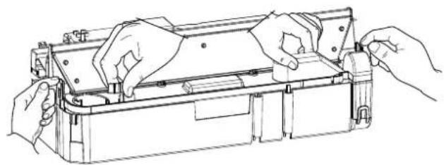
- There are two clips, one on the left and one on the right hand side of the sump, holding down the sump. On the left side press in the clip with one hand and with the other lift the nozzle our of the clip. Repeat this for the right side (Fig.8). The nozzle is now released, lift this off and place aside (Fig.9)
- Gently lift up the sump (Fig.10), taking care to keep level so as not to spill any water. Sit the sump in the sink.
- Carefully empty the sump into the sink taking note that the transducer is held in place by a retaining clip.
- Put a small amount of washing up liquid into the sump, and using a soft brush, gently clean all surfaces in the sump and gently clean the transducer including the metal discs located in the top grooved surface.
- When cleaned, thoroughly rinse the sump with clean water to remove all traces of washing up liquid.
- Clean the Nozzle with the a soft brush and flush out thoroughly with water.
- Reverse the above steps to reassemble.
Transducer
The transducer is a consumable item and may need to be replaced through time, depending on its usage. Replacement transducers can be purchased from our website http://spares.dimplex.co.uk. The transducer is fixed in the sump with a plastic clip. If you need to replace your transducer
- Follow the steps 1-5 in the CLEANING Sump section under 'Maintenance' to gain access to the transducer
- Press the clip back and lift the transducer upwards out of its holder.
- Remove the cone by turning it clockwise and place it on your new transducer. Turn the cone anticlockwise until tight to fix it in place
- Reverse steps 5-1 to reassemble
Air fi Iter
- Gently lift out the fuelbed and place carefully on the ground.
- Gently slide the air filter upwards out of its plastic holder. (Fig.11)
- Gently rinse with water in the sink and dry with fabric towel before returning.
- Replace the filter making sure that the coarse black filter is facing the front of the fire.
- Replace the fuelbed.
Additional Information
AFTER SALES SERVICE
Your product is guaranteed for one year from the date of purchase. Within this period, we undertake to repair or exchange this product free of charge (excluding transducer discs & subject to availability) provided it has been installed and operated in accordance with these instructions. Your rights under this guarantee are additional to your statutory rights, which in turn are not affected by this guarantee.
RECYCLING
For electrical products sold within the European Community - At the end of the electrical products useful life it not be disposed of with household waste. Please recycle where facilities exist. Check with your Local Authority or retailer for recycling advice in your country.
PATENT / PATENT APPLICATION
Products within the Optimyst range are protected by one or more of the following patents and patent applications:
Great Britain GB2460259B, GB2475794B, GB2418014, EP2029941, GB2436212, GB2402206B
United States US8413358, US8136276, US7967690, US8574086
Russia RU2434181
European EP2029941, EP2315976, EP1787063 (A1), EP2388527, EP2029941,
China CN101883953A, CN102105746A, CN101057105 (A), CN101438104
Australia AU2009248743A1, AU2007224634
Canada CA2725214, CA2579444, CA2645939
South Africa ZA2008/08702
Mexico MX2008011712
South Korea KR101364191
Japan JP5281417, JP5496291
Brazil BRP10708894
India 4122/KOLNP/2008
New Zealand NZ571900
Troubleshooting
| Symptom Cause Corrective Action | ||
| The flame effect will not start. | Mains plug is not plugged in.Low water level.Low voltage connector not connected properly. (See Fig.7) | Check plug is connected to wall socket correctly.Check that the water tank is full and there is water in the sump.Check that the connector is inserted correctly. (See Fig.7) |
| The flame effect is too low. | Flame effect control knob is set too low.The Disc in the transducer might be dirtyThe wire from the Transducer Unit is sitting over the disc | Increase level of flame by pressing ♠on your remote or receiverClean the Disc with a soft brush. See ‘Maintenance.’ for a step by step procedure.Direct the wire to the back of the sump and make sure it sits into the side slot exiting the sump. |
| Unpleasant smell when unit is used. | Dirty or stale water.Using unfi itered tap water. | Clean the unit as described under maintenance.Use only fi itered tap water. |
| The flame effect has too much smoke. | Flame effect setting is too high. | Turn down the flame effect. Give the flame generator some time to adjust to the new setting. |
Introduction
Europe EP2029941, EP2315976, EP1787063 (A1), EP2388527, EP2029941,
Chine CN101883953A, CN102105746A, CN101057105 (A), CN101438104
Australie AU2009248743A1, AU2007224634
Canada CA2725214, CA2579444, CA2645939
natural_image
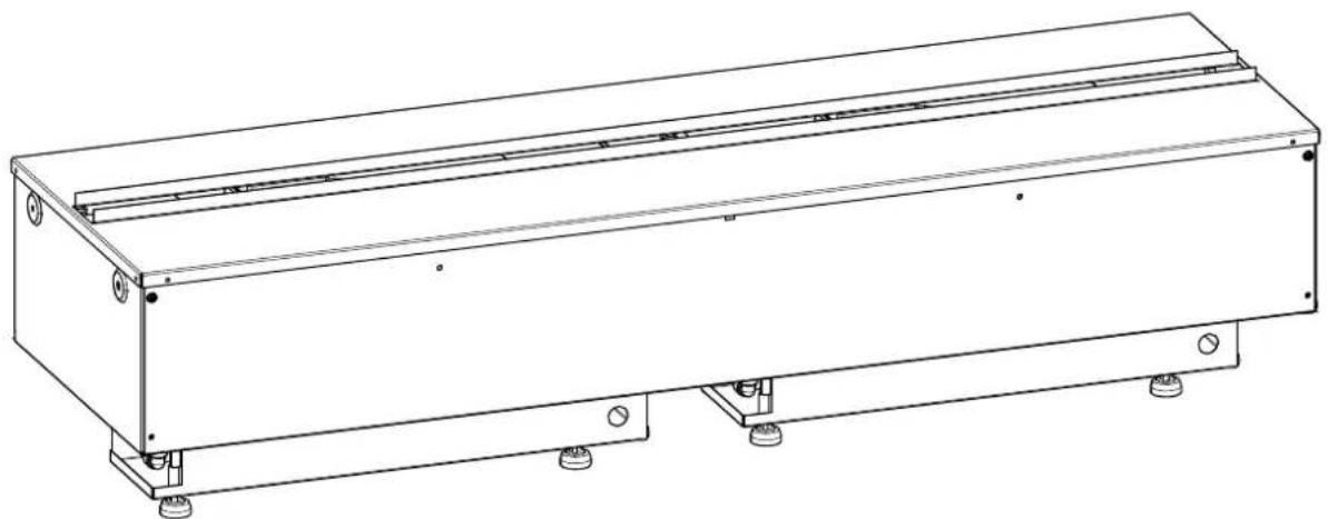
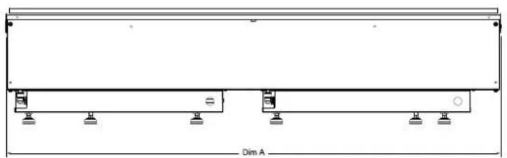
Pure electrical circuit lines without any symbols| MODEL DIM 'A' |
| OMC500M 508mm |
| OMC1000M 1017mm |
natural_image
Technical line drawing of a structural beam with supports and dimension label Dim A (no text or symbols beyond basic geometry)
text_image
230 305Fig.1
natural_image
Technical line drawing of a mechanical component with no visible text or symbols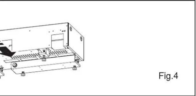
natural_image
Technical line drawing of a mechanical assembly with no visible text or symbols
text_image
OMC500M OMC1000M Fig.5a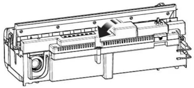
natural_image
Technical line drawing of a mechanical device with internal components and mounting holes (no text or symbols)Fig.5b
text_image
Switch 'A'OMC500M
text_image
Row of eight audio and sound playback icons including power, kHz, alarm, speaker, and microphoneFig.6
OMC1000M
text_image
Row of eight audio and sound control icons including power, music, alarm, speaker, and microphone symbols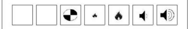
natural_image
Row of eight black-and-white icons including play button, radio, and speaker (no text or symbols)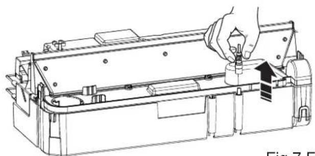
natural_image
Technical line drawing of a mechanical device with a hand adjusting a component (no text or symbols visible)Fig.7 Fig.8
natural_image
Line drawing of hands assembling or adjusting a mechanical component (no text or symbols visible)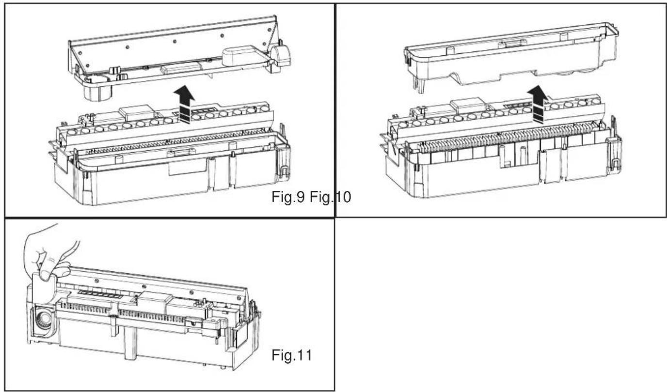
DE - Garantie
UK - Warranty The warranty conditions in the country of purchase apply to this appliance. Information can be obtained at any time from the retailer from whom the appliance was purchased. For claims under guarantee the sales receipt must be produced and the claims must be forwarded within the guarantee period. The right to claim under guarantee expires in case that the device has been damaged, used in an inappropriate way or that unauthorized manipulations have been carried out.
- Warranty Card
- Guarantee Period (in Years)
- Model(s)
- Date of Purchase
- Stamp & Signature of retailer
- Fault/Defect
- Contact Number & Address