GIB 6004 X - Cooker CATA - Free user manual and instructions
Find the device manual for free GIB 6004 X CATA in PDF.
| Feature | Details |
|---|---|
| Type of stove | Gas stove |
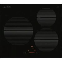
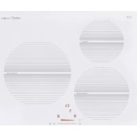
| Number of burners | 4 burners |
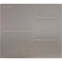
| Dimensions (W x D x H) | 60 cm x 60 cm x 85 cm |
| Burner power | From 1 kW to 3 kW depending on the burner |
| Oven type | Gas oven |
| Oven capacity | 60 liters |
| Oven features | Grill, traditional cooking |
| Safety system | Safety device on burners |
| Materials | Stainless steel |
| Maintenance | Easy cleaning thanks to smooth surface |
| Energy consumption | Energy class not specified |
| Included accessories | Grill rack, baking tray |
| Warranty | 2 years |
Frequently Asked Questions - GIB 6004 X CATA
Download the instructions for your Cooker in PDF format for free! Find your manual GIB 6004 X - CATA and take your electronic device back in hand. On this page are published all the documents necessary for the use of your device. GIB 6004 X by CATA.
USER MANUAL GIB 6004 X CATA
238/286 286/333 2,50/3,00 2,50/3,00 3,00/3,50 3,00/3,50 1720/2064 2064/2471 2451/2860 2924/341127 Dear customer, We thank you and congratulate you on your choice. This new carefully designed product, manufactured with the highest quality materials, has been carefully tested to satisfy all your cooking demands. We would therefore request you to read and follow these easy instructions which will allow you to obtain excellent results right from the start. May we wish you all the very best with your modern appliance! THE MANUFACTURER INDEX
MODELS INCLUDING BATTERIES
Warranty Package Installation and efficiency
Installation Gas connection Electrical connection Injectors characteristics THIS APPLIANCE IS CONCEIVED FOR DOMESTIC USE ONLY. THE MANUFACTURER SHALL NOT IN ANY WAY BE HELD RESPONSIBLE FOR WHATEVER INJURIES OR DAMAGES ARE CAUSED BY INCORRECT INSTALLATION OR BY UNSUITABLE, WRONG OR ABSURD USE. EN28
INSTRUCTIONS FOR USE
Installation All the operations concerned with the installation (electrical connection) must be carried out by qualified technicians, in terms with the standards in force, for specific instructions, kindly read the part reserved for the installation technician. Use Gas burners (fig. 1). The ignition of the gas burner is carried out by putting a small flame to the upper part holes of the burner, pressing and rotating the corresponding knob in an anti-clockwise manner, until the maximum position has coincided with the marker. When the gas burner has been turned on, adjust the flame according to need. The minimum position is found at the end of the anti-clockwise rotation direction. In models with automatic ignition, operate the knob as described above, pressing simultaneously, the corresponding push-button. For models with automatic/simultaneous (with one hand) ignition, it is sufficient to proceed as described above using the corresponding knob. The electric, spark, between the ignition plug and the burner provides the ignition of the burner itself After ignition, immediately release the push-button and adjust the flame according to need. For models with a thermoelectric safety system, the burner is ignited as in the various cases described above, keeping the knob fully pressed on the maximum position for approximately 3/5 seconds. After releasing the knob, make sure the burner is actually lit. N.B.: - we recommend the use of pots and pans with a diameter matching that of the burner, thus preventing the flame from escaping from the bottom part and surrounding the pot - do not leave any empty pots or pans on the fire - do not use any tools for grill-cooking on Crystal hobs. When cooking is finished, it is also a good norm to close the main gas pipe tap and/or cylinder. fast Ф 18 x 24 semifast Ф 14 x 18 auxiliary Ф 12 x 14 fish* 18 x 30 GAS
- with reduction grid Fig. 129
MODELS INCLUDING BATTERIES
Warranty Warranty (warranty service) does not include the battery. The gas hob manufacturer is exempt of any responsibility for the malfunction of batteries. Package Some models include batteries (D or LR20 or R20S type; 1,5 V) for the autoignition function. Capacity (device) to install the battery located at the bottom back left side of the hob as shown in the picture. If the battery is not included and should be purchased separately. Installation and efficiency Before installing your hob on a tabletop, first insert a battery (checking “+” and “-”) into a special device located at the bottom back left side of the hob as shown in the picture. Before final fixation of the hob in a tabletop with special sealer (liner) with adhesive basing (included) make sure autoignition works correctly. In order to do it, push any knob turning it counterclockwise so that its index points at the flame symbol waiting until there are sparks followed by characteristic cracks (clicks). In case that autoignition doesn’t work properly, check if batteries are unloaded and proceed to change it. If problems aren’t solved, call the Customer Service or maintenance. Maintenance Gas/Electrical Prior to any operation, disconnect the appliance from the electrical system. For long-life to the equipment, a general cleaning operation must take place periodically, bearing in mind the following:
- the glass, steel and/or enamelled parts must be cleaned with suitable non-abrasive or corrosive products (found on the market). A void chlorine-base products (bleach, etc.);
- avoid leaving acid or alkaline substances on the working area (vinegar, salt, lemon juice, etc.).
- the wall baffle and the small covers (mobile parts of the burner) must be washed frequently with boiling water and detergent, taking care to remove every possible encrustation. Dry carefully and check that none of the burner holes is fully or partially clogged;
- the electrical parts are cleaned with a damp cloth and are lightly greased with lubricating oil when still warm.
- the stainless steel grids of the working area, after having been heated, take on a bluish tint which does not deteriorate the quality. To bring colour back to its original state, use a slightly abrasive product. N.B.: - Cleaning of the taps must be carried out by qualified personnel, who must be consulted in case of any fimctioning anomaly. Check periodically the state of conservation of the flexible gas feed pipe. In case of leakage, call immediately the qualified technicians for its replacement.30 Maintenance vitroceramic surface (Fig.-2) First of all remove stray food bits and grease drops from the cooking surface with the special scraper (fig. 2). Then clean the hot area as best as possible with SIDOL, STAHLFIX or other similar products with a papertowel, then rinse again with water and dry with a clean cloth. Pieces of aluminum foil and plastic material which have inadvertently melted or sugar remains or highly sacchariferous food have to be removed immediately from the hot cooking area with the special scraper (fig. 2). This is to avoid any possible damage to the surface of the top. Under no circumstances should abrasive sponges or irritating chemical detergents be used such as oven sprays or spot removers. Do not use steam cleaning appliances to clean the cooking surface. Fig. 2
INSTRUCTIONS FOR THE INSTALLER
Installation This appliance is not provided with a combustion product discharge. It is recommended that it be installed in sufficiently aerated places, in terms of the laws in force. The quantity of air which is necessary for combustion must not he below
/h for each kW of installed power. See table of burner power. Positioning The appliance can be fitted into a working area as illustrated on the corresponding figure. Before positioning the hob, fit the seal around the entire peripnery of the hole cut in the worktop. Fig. 331
- that the plant is fitted with an efficient earth connection, following the standards and law provisions in force. The earth connection is compulsory in terms of the law. Should there be no cable and/or plug on the equipment, use suitable absorption material for the working temperature as well, as indicated on the matrix plate. Under no circumstance must the cable reach a temperature above 50 °C of the ambient temperature. Should a direct connection to the network be required, it will be necessary to interpose an omnipolar switch with minimum aperture between the 3 mm. contacts, dimensioned to bear the plate load and it must follow the standards in force (the yellow/green earth cable must not be interrupted by the switch). The plug or omnipolar switch must be easily reached on the installed equipment. The manufacturers decline any responsibility in the event of non-compliance with what is described above and the accident prevention norms not being respected and followed. If the mains cable becomes damaged, replace it immediately with a cable or special cable set obtained from the manufacturer or from after sales service. The use of silicone for the sealing is prohibited. It is only permitted to use the seal provided. The use of clay pots and heat diffusers is prohibited. GAS CONNECTION (Fig. 4) Connect the appliance to the gas cylinder or to the installation according to the prescribed standards in force, and ensure beforehand, that the appliance matches the type of gas available. Otherwise, see “Adaptation to various types of gas”. Furthermore, check that the feed pressure falls within the values described on the table: “Injectors characteristics”. Rigid/semirigid metal connection Carry out the connection with fittings and metal pipes (even flexible pipes) so as to obtain counter stress the inner parts of the appliance. N.B.: - token the installation has been carried out, check the perfect sealing of the entire connection system, by using a soapy solution. G 1/2 ISO 7/1 ISO 228/1 (FR) Fig. 4 Electrical connection (Fig. 5) Prior to carrying out the eleciricat connection, please ensure that:
- the plant characteristics are such as to follow what is indicated on the matrix plate placed at the bottom of the working area;32 Fig. 5 CABLE-CLAMP
- that the plant is fitted with an efficient earth connection, following the standards and law provisions in force. The earth connection is compulsory in terms of the law. Should there be no cable and/or plug on the equipment, use suitable absorption material for the working temperature as well, as indicated on the matrix plate. Under no circumstance must the cable reach a temperature above 50 °C of the ambient temperature. Should a direct connection to the network be required, it will be necessary to interpose an omnipolar switch with minimum aperture between the 3 mm. contacts, dimensioned to bear the plate load and it must follow the standards in force (the yellow/green earth cable must not be interrupted by the switch). The plug or omnipolar switch must be easily reached on the installed equipment. The manufacturers decline any responsibility in the event of non-compliance with what is described above and the accident prevention norms not being respected and followed. If the mains cable becomes damaged, replace it immediately with a cable or special cable set obtained from the manufacturer or from after sales service. Adaptation to various types of gas (Fig. 6) Should the appliance be pre-set for a different type of gas than that available, proceed as follows:
- replace the injectors (Fig. 6) with the corresponding type of gas to be used (see table “Injectors characteristics”). Fig. 633
- to adjust to the minimum, use a screwdriver on the screw placed on the tap (Fig. 8) after turning the tap to its minimum position. For LPG (butane/propane) screw tight. Fig. 7 Fig. 8 (cm) R L1 L2 L3 L4