
6614 - Saw Hobart - Free user manual and instructions
Find the device manual for free 6614 Hobart in PDF.
| Product Type | Meat Saw |
| Brand | Hobart |
| Model | 6614 |
| Category | Saw |
| Motor | 3 HP, electric, water resistant |
| Power supply | Three-phase up to 250 V, transformer for 115 V if needed |
| Blade speed | Not specified in the manual |
| Blade width | Various widths available |
| Main material | Stainless steel (table, carriage, covers) |
| Main functions | Meat sawing, mobile carriage with stainless steel ball bearings, integrated or standard product pusher, adjustable gap plate, adjustable upper blade guide |
| Safety devices | Upper/lower blade guard, column guard, product pusher, carriage latch, pulley covers |
| Cleaning | Tool-free disassembly of tables, carriage, pulleys, blade guide, scrapers; cleanable with high-pressure jet or in sink |
| Maintenance | Lubrication of bearings and rods with mineral oil, adjustment of sliding bar |
| Blade | Long-lasting non-sharpened blade, replacement available |
| Options | Optional integrated push carriage |
| Weight | Not specified, approximately 150-200 kg (estimate) |
Frequently Asked Questions - 6614 Hobart
User questions about 6614 Hobart
0 question about this device. Answer the ones you know or ask your own.
Ask a new question about this device
Download the instructions for your Saw in PDF format for free! Find your manual 6614 - Hobart and take your electronic device back in hand. On this page are published all the documents necessary for the use of your device. 6614 by Hobart.
USER MANUAL 6614 Hobart
MODEL 6801/6614 MEAT SAW
MODEL
6801 ML-141167
6614 ML-141220
6614 ML-134097
PREVIOUS MODELS COVERED BY THIS MANUAL:
6614 ML-134049
HOBART
701 S. RIDGE AVENUE
TROY, OHIO 45373
937 332-3000
www.hobartcorp.com
FORM 48152 Rev. A (July 2024)
INsT
R U
13/14
A
N_S
Installation, Operation, and Care of MODEL 6801/6614 MEAT SAW READ INSTRUCTIONS BEFORE USING SAW SAVE THESE INSTRUCTIONS
GENERAL
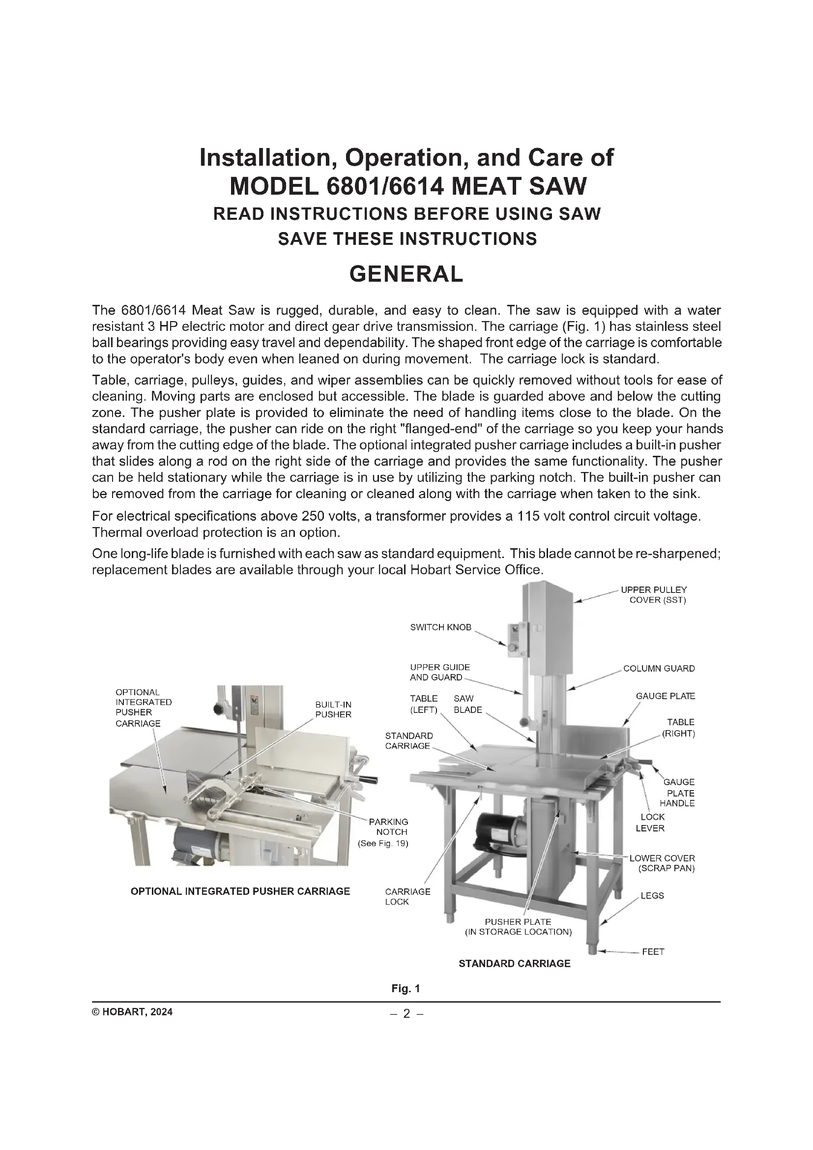
The 6801/6614 Meat Saw is rugged, durable, and easy to clean. The saw is equipped with a water resistant 3 HP electric motor and direct gear drive transmission. The carriage (Fig. 1) has stainless steel ball bearings providing easy travel and dependability. The shaped front edge of the carriage is comfortable to the operator's body even when leaned on during movement. The carriage lock is standard.
Table, carriage, pulleys, guides, and wiper assemblies can be quickly removed without tools for ease of cleaning. Moving parts are enclosed but accessible. The blade is guarded above and below the cutting zone. The pusher plate is provided to eliminate the need of handling items close to the blade. On the standard carriage, the pusher can ride on the right "flanged-end" of the carriage so you keep your hands away from the cutting edge of the blade. The optional integrated pusher carriage includes a built-in pusher that slides along a rod on the right side of the carriage and provides the same functionality. The pusher can be held stationary while the carriage is in use by utilizing the parking notch. The built-in pusher can be removed from the carriage for cleaning or cleaned along with the carriage when taken to the sink.
For electrical specifications above 250 volts, a transformer provides a 115 volt control circuit voltage. Thermal overload protection is an option.
One long-life blade is furnished with each saw as standard equipment. This blade cannot be re-sharpened; replacement blades are available through your local Hobart Service Office.
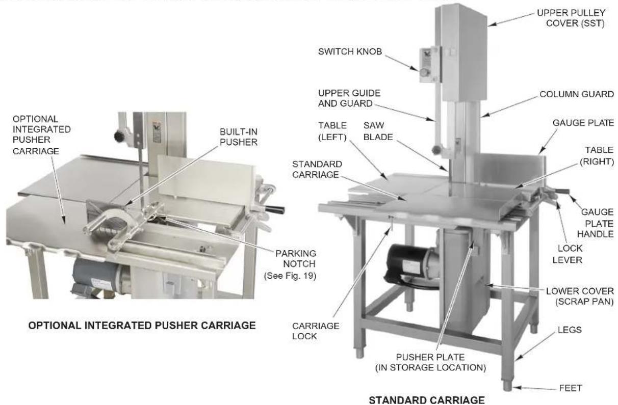
Fig. 1
INSTALLATION
UNPACKING AND ASSEMBLY
The saw was inspected before leaving the factory. The carrier assumes full responsibility for the safe delivery upon acceptance of the shipment. Check for possible shipping damage immediately after receipt.
If the saw is found to be damaged, complete the following steps:
- Carrier must be notified within five business days of receipt.
- Carrier's local terminal must be notified immediately upon discovery (note time, date, and who was spoken to), and follow up and confirm with written or electronic communication.
- All original packing materials must be kept for inspection purposes.
- The saw cannot have been moved, installed, or modified.
- Notify Hobart customer care at (800) 333-7447.

Fig. 2
Prior to installation, test the electrical service to make sure it agrees with the specifications on the machine data plate (Fig. 2) located on the column.
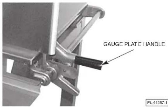
Packed in a packet attached to the table compartment are the pusher plate, when a standard carriage is provided, and the gauge plate handle. Place the pusher plate in its storage location under the carriage support (Fig. 3). Assemble the gauge plate handle to the gauge plate support by screwing the stud into the threaded hole (Fig. 4).
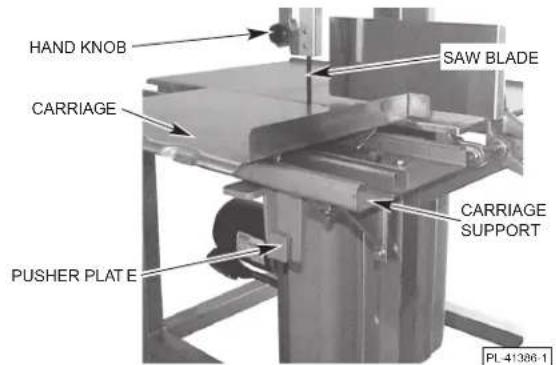
Fig. 3 Fig. 4
LEVELING
Place the saw in its operating location. Using a spirit level, level the saw front-to-back and side-to-side by turning the threaded feet in or out. The foot will stop turning when it has achieved its maximum adjustment height.
WARNING Disconnect the electrical power to the machine and follow lockout/tagout procedures.
SAW BLADE
The saw blade must be installed so the teeth on the cutting edge point to the right and down (Fig. 5).
UPPER GUIDE AND GUARD ASSEMBLY
When the saw is off, the hand knob (Fig. 5) can be used to position the upper guide and guard assembly so the cutting zone is only as high as necessary for the piece being cut. The hand knob is not loosened during raising or lowering — it should remain tightly secure.
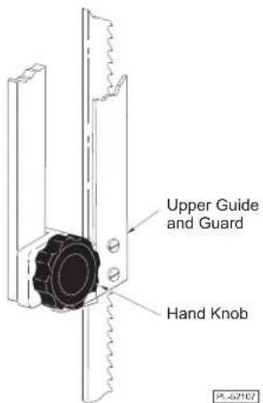
Fig. 5
COLUMN GUARD
The column guard (Fig. 6) covers the return loop of the moving blade and must always be in place during sawing. To remove the column guard for cleaning or blade change, first remove the right table and the upper pulley cover. You may want to remove the lower cover (scrap pan) as well. Then, lift the column guard up to free it from the two shoulderscrew heads on the column that it hangs from.
TABLES — RIGHT AND LEFT
During use, the right and left tables (Fig. 6) are secured underneath by pins and clamps. To remove the tables for cleaning: raise the gauge plate to its vertical position; lift the right side of the right table up; and, remove the table from the two pins. After the right table is removed, the left table can be removed: lift the left side of the left table up and shift it to the right to free it from the two pins.
UPPER PULLEY COVER
The stainless steel upper pulley cover (Fig. 6) should be installed on the two hinge pins of the stainless steel upper pulley baffle and securely latched during saw use. To remove the stainless steel upper pulley cover for cleaning, unlatch and open the stainless steel upper pulley cover; then, lift straight up and off the hinge pins.
LOWER COVER (SCRAP PAN)
During use, the lower cover (Fig. 6) acts as a scrap pan, accumulating bone dust and debris from the blade scrapers and pulley wiper that are located on the lower panel (Fig. 7). To remove the lower cover (scrap pan) for cleaning, release the clip at the top; pull out and lift the lower cover from the groove at the bottom of the lower panel.
BLADE SCRAPERS
Two blade scrapers wipe the blade during sawing
to accumulate bone dust and debris inside the lower cover (scrap pan). The front scraper points up and the rear scraper points down (Fig. 7). After the blade is removed, the scrapers can slide off their mounting blocks for cleaning.
PULLEY WIPER
The pulley wiper (Fig. 7) scrapes bone dust and debris from the lower pulley during use. The pulley wiper can be removed for cleaning by springing the wiper up and sliding it off the pins.
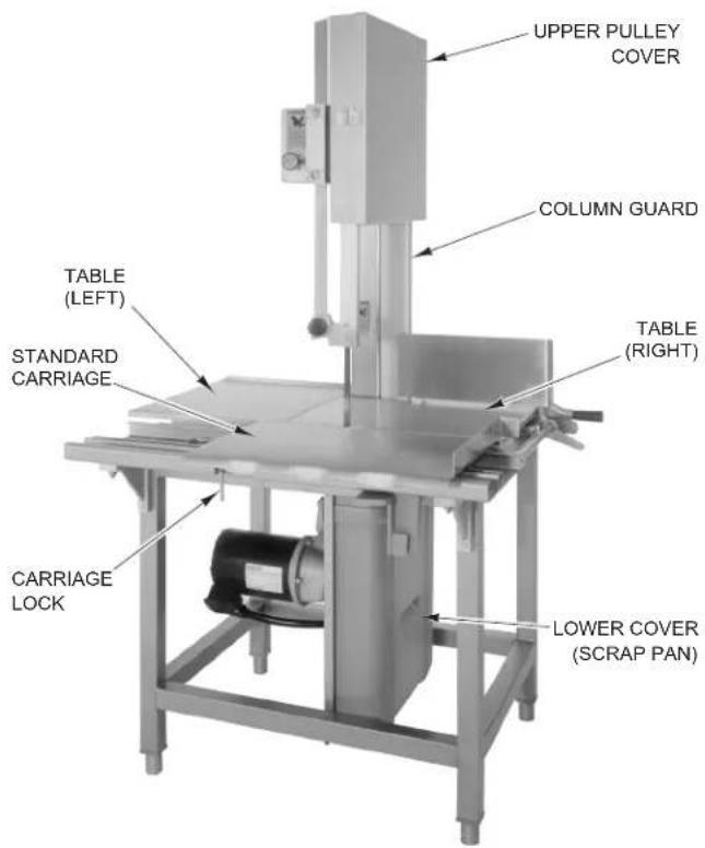
Fig. 6
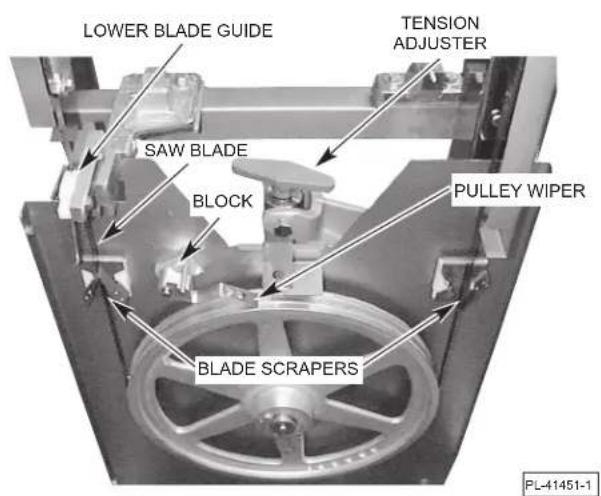
Fig. 7
LOWER PULLEY
The lower pulley is assembled on the lower pulley shaft. The latch on the lower pulley should be seated in the groove of the pulley shaft (Fig. 8). The lower pulley can be removed after the blade has first been loosened and removed and the lower pulley latch is moved out of the groove of the lower pulley shaft.
UPPER PULLEY
The upper pulley is assembled on the upper pulley shaft. The round retainer on the upper pulley shaft should be positioned out-of-center when latched (Fig. 9). The upper pulley can be removed after the blade has first been loosened and removed and the round retainer is moved to the center of the upper pulley shaft.
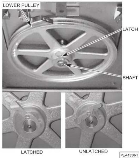
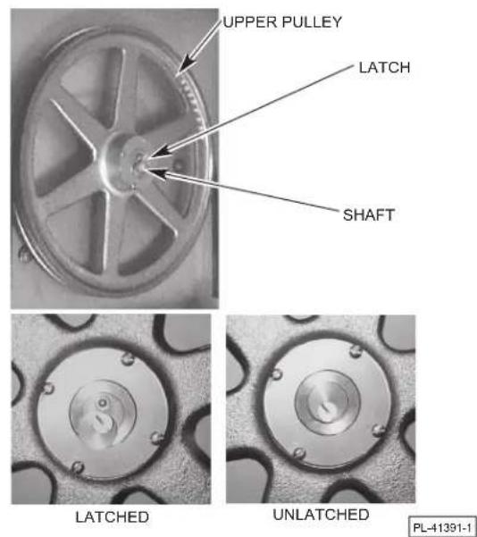
Fig. 8 Fig. 9
SCRAP TRAY
During use, the scrap tray should be installed between the left-hand table and the carriage support (Fig. 10). The scrap tray slides into place, resting on the frame between the carriage support and table. The angled side of the scrap tray is located nearest the blade.
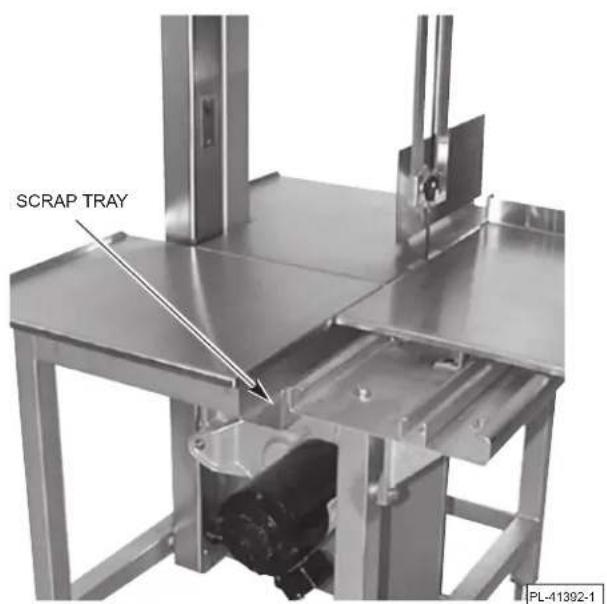
Fig. 10
CARRIAGE - STANDARD OR INTEGRATED PUSHER
In use, the carriage can roll back and forth between the left carriage stop (Fig. 11) and the right carriage stop, assuming the spring-loaded carriage lock (Fig. 6) has not locked the carriage in a stationary position.
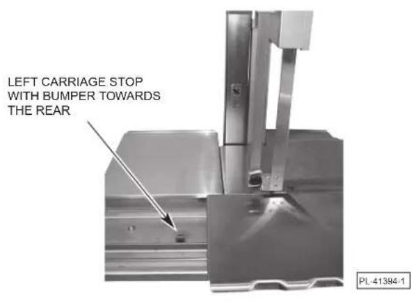
To remove the carriage, turn either of the carriage stops 90 degrees so the bumper is toward the rear (Fig. 12). Roll the carriage off either end while lifting it free of the carriage support structure (Fig. 11).
To reinstall the carriage, hold the carriage so the bearings (underneath) are aligned with the carriage support structure. Roll the carriage into place. Return the carriage stops so the carriage is stopped at both ends.
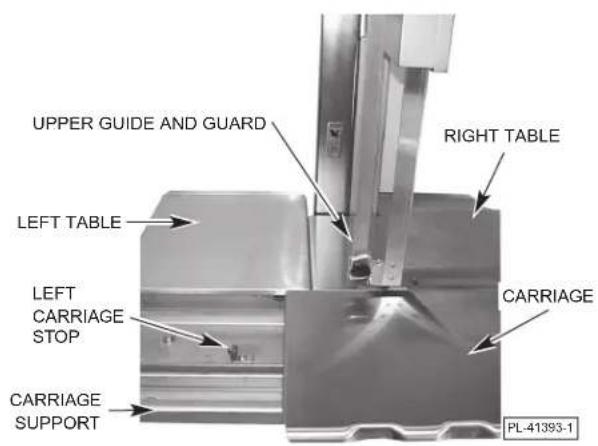
Fig. 11 Fig. 12
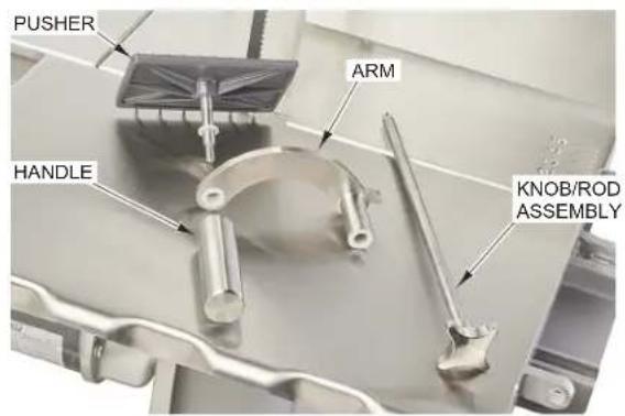
INTEGRATED PUSHER CARRIAGE
For ease of cleaning, the pusher can be removed from the integrated pusher carriage by unscrewing the knob and pulling the knob/rod assembly out of the pusher arm. The handle and pusher can also be removed from the arm by unscrewing the handle. See Figure 13 for the assembled view and Figure 14 for the disassembled view of the integrated pusher carriage components. Replace pusher on the integrated pusher carriage after cleaning.
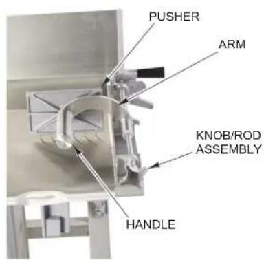
Fig. 13 Fig. 14
LOWER BLADE GUIDE
The lower blade guide assembly fits in the lower guide holder (Fig. 15). The blade fits in the slots of both the steel saw blade guide and the plastic guide. When the right table is removed and the plastic guide is hinged up, the lower blade guide assembly can be removed for cleaning by lifting it out of the lower guide holder.
The steel saw blade guide is available in various widths depending on the blade being used. Contact Hobart Service to change the steel saw blade guide for other blade widths.
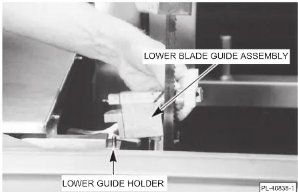
Fig. 15
REMOVING THE BLADE
Remove the upper and lower pulley covers. Raise the gauge plate to its vertical position. Remove the right table by lifting its right side and sliding the table to the right to free it from the locating pins. Remove the column guard. Turn the tension adjuster counterclockwise until it stops (this will release tension on the blade by raising the lower pulley). Raise the plastic blade guide on the lower blade guide assembly and release the blade from the upper and lower blade guides. Free the blade from the blade scrapers in the lower pulley area and release it from the pulleys. Remove the blade.
Make sure the pulleys are properly installed and the pulleys are latched (Figs. 8 & 9). Install the new blade with the teeth on the cutting edge pointing to the right and down as you face the front of the saw. The blade must fit between the Vs on the blade scrapers in the slots of the upper and lower blade guides and must not touch any of the pulley flanges. The lower blade guide must be installed after the blade is installed. When the blade is in position, see BLADE TENSION, below, to adjust the tension properly. Refer to LOWER BLADE GUIDE, above, if the blade width of the new blade is different than the blade width of the old blade. Reinstall any removed parts.
BLADE TENSION
After the blade has been installed, set the blade tension by turning the tension adjuster (Fig. 7) clockwise until it stops.
ELECTRICAL CONNECTIONS
WARNING Electrical and grounding connections must comply with the applicable portions of the national electrical code and/or other local electrical codes.
WARNING Disconnect the electrical power to the machine and follow lockout/tagout procedures.
A 7/8'' diameter hole for 1/2'' trade size conduit is located at the upper rear of the column. Use watertight connections. Refer to the machine data plate and the wiring diagram located on the machine when making the electrical connection. Connect the electrical power supply leads to the pigtail leads; use copper wire rated at least 60^ for the connection.
CHECK MOTOR ROTATION (THREE-PHASE MACHINES)
If the motor does not rotate so the teeth on the cutting edge of the saw blade run downward as you look at the cutting zone, correct the rotation using the following procedure:
WARNING Disconnect the electrical power to the machine and follow lockout/tagout procedures.
Interchange any two of the incoming power supply leads. Reconnect the power supply and turn the saw momentarily on and off to verify correct rotation.
CONTROL BOX HEATER
The saw has a heater in the control box to keep the controls dry. The heater is automatically ON when the machine is electrically connected. The saw should be connected to the power supply EXCEPT when performing assembly, disassembly, cleaning, or maintenance on the saw.
CLEAN SAW BEFORE USE
The saw must be thoroughly cleaned and sanitized after installation and before use. Refer to CLEANING, page 11.
OPERATION
WARNING Safety devices incorporated in this saw must be in their correct positions at all times. Do not operate without covers and guards in place. Failure to follow these instructions may result in serious injury.
SAFETY FEATURES
Upper Guide and Guard Assembly
Before turning the saw on, position the upper guide and guard assembly by grasping the hand knob and sliding up or down so the cutting zone is only as high as necessary for the piece being cut. Always fully lower the upper guide and guard assembly when the saw is not in use.
Doors, Covers, and Guards
All doors, covers, and column guards must be in their operating position (closed) while the machine is running.
Pusher Plate
Always keep hands away from the blade and maintain control of the product. Use the pusher plate as described (page 10) to maintain a safe distance from the cutting edge of the saw blade.
CONTROLS
Switch Knob Pull turns the saw on.
Push turns the saw off.
NEVER LEAVE THE SAW UNATTENDED WHILE THE SAW IS RUNNING. ALWAYS TURN OFF THE SAW AND LOWER THE UPPER GUIDE AND GUARD ASSEMBLY WHEN THE SAW IS NOT IN USE.
SAWING
Place product on carriage. Position the upper guide and guard assembly and the gauge plate before starting the machine.
If using the traveling carriage . . .
Stand in front of machine. Lean lightly against the front of the carriage as you move the carriage to the left, passing the product through the blade at a steady and uniform rate.
Use your left hand to remove and stack cuts, always reaching behind the blade. NEVER REACH ACROSS THE CUTTING EDGE OF THE BLADE. Return the carriage to the right, pulling the product
toward you and away from the blade.
If using the stationary carriage . . .
The carriage may be locked in a stationary position by pulling the spring-loaded carriage lock out, rotating it 90^ and sliding the carriage until the lock engages (Fig. 16). To unlock the carriage, pull the carriage lock out and rotate it 90^ so it rests on its bracket. When sawing with stationary table, observe the same safety procedure of reaching behind the blade when removing or stacking product. NEVER REACH ACROSS THE CUTTING EDGE OF THE BLADE.
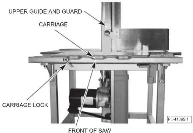
Fig. 16
GAUGE PLATE
When making several cuts of the same thickness (or when using the pusher plate), set the gauge plate as desired (Fig. 17) by pushing the lock lever and sliding the gauge plate to the thickness you want. A reference scale on the table indicates the thickness of cut. If the gauge plate is not needed, you may release the lock lever and move the gauge plate to the rear or raise the gauge plate to a vertical position to keep it out of the way.
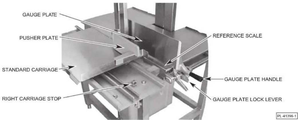
Fig. 17
PUSHER PLATE - STANDARD CARRIAGE
The pusher plate is used to hold meat against the gauge plate when slicing small products or the last few cuts of a product. A slot in the pusher plate and a stop on the right "flanged-end" of the carriage is provided for proper positioning of the pusher plate (Fig. 17). Hold the pusher plate handle with your right hand and always maintain a safe distance from the blade. When not in use, keep the pusher plate under the carriage support (Fig. 3).
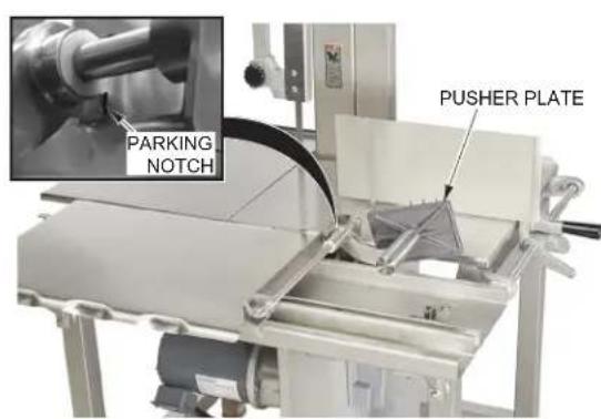
PUSHER PLATE - INTEGRATED PUSHER CARRIAGE
The pusher plate is built into the carriage. Hold the pusher plate handle with your right hand and move the pusher plate along the rod while maintaining a safe distance from the blade (Fig. 18). The pusher plate can be stored in the parked position when not in use (Fig. 19).
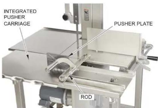
Fig. 18 Fig. 19
CLEANING
CLEANING AND SANITIZING
WARNING Disconnect the electrical power to the machine and follow lockout/tagout procedures.
The saw must be thoroughly cleaned and sanitized:
Before first use;
After each day's operation;
Anytime it is not to be used for an extended period of time; or
Before being put into operation after an extended downtime.
The saw can be cleaned with high-pressure cleaning equipment (available from other suppliers) or it can be disassembled and its components cleaned in a sink. In either case, a neutral pH cleaning agent mixed per the supplier's instructions should be used. After washing, thoroughly sanitize, rinse, and dry the saw and all components.
Disassemble the following saw components to allow access to all areas for cleaning . . .
- Upper Pulley Cover - Pulley Wiper
- Lower Cover (Scrap Pan) - Blade Scrapers
- Tables — Right and Left-Hand • Lower Blade Guide Assembly
- Scrap Tray - Saw Blade
- Pusher from Integrated Pusher Carriage
- Upper Guide and Guard Assembly (unscrew Hand Knob to disassemble)
- Column Guard - Upper and Lower Pulleys
Carriage
If using High-Pressure Cleaning Equipment . . .
Scrape the machine and its components to remove any scrap particles before cleaning.
Thoroughly hose the saw and its components following the equipment supplier's instructions. Be sure to get the hose stream into all corners. Stubborn soil may require a little brushing.
If using Sink Cleaning . . .
Use a cloth or brush on base unit. Thoroughly wash, sanitize, rinse, and dry.
Before reassembly, a light coating of tasteless mineral oil should be applied to all metal surfaces. Lubricate the six ball bearings underneath the carriage with a small amount of mineral oil. Apply a few drops of mineral oil to the gauge plate slide rod and work the gauge plate assembly back and forth a few times. If the saw has the optional integrated pusher carriage, follow the same process for the integrated pusher slide rod.
Reassemble the saw components in reverse order of disassembly making sure all parts are properly assembled.
Reconnect Electrical Power Supply
The saw has a heater in the control box to keep the controls dry. The heater is automatically ON when the machine is electrically connected. The saw should be connected to the power supply EXCEPT when performing assembly, disassembly, cleaning, or maintenance on the saw.
MAINTENANCE
WARNING Disconnect the electrical power to the machine and follow lockout/tagout procedures.
LUBRICATION
The motor has permanently lubricated ball bearings and requires no additional lubrication.
The slide bar for the upper guide and guard assembly also requires no lubrication.
After cleaning, apply a small amount of mineral oil to the six ball bearing rollers underneath the carriage, to the gauge plate slide rod, and to the pulley shafts.
SLIDE BAR ADJUSTMENT
NOTE: The slide bar must be free to move up and down without binding, but must stay in any position that it is moved to.
- Loosen the two set screws on the side of the slide bar housing (Fig. 20).
- Remove the two hole plugs (Fig. 20) on the front of the slide bar housing.
- Unscrew the two screws in the front of the slide bar housing (Fig. 21).
- Raise the slide bar and slowly tighten the two side set screws (Fig. 20) until the slide bar is just held in place.
- Tighten the two front screws (Fig. 21).
- Check for free up and down movement of the slide bar and that it stays in any position it is moved to. Repeat steps 1 and 3 thru 6 as required.
- Reinstall the hole plugs (Fig. 20).
CHANGING SAW BLADES
If changing saw blades, disassemble components as described in REMOING THE BLADE, page 7, and the instructions for any component throughout the manual. Make sure wipers, scrapers, and all other components are properly reassembled. Refer to BLADE TENSION, page 7. Refer to LOWER BLADE GUIDE, page 7.
SERVICE
Contact your local Hobart Service Office for any repairs or adjustments needed on this equipment.
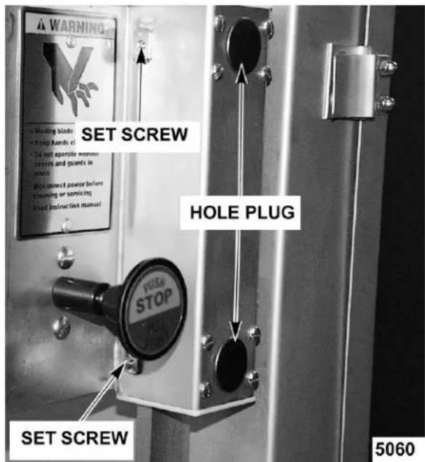
Fig. 20
Fig. 21
SCIE À VIANDE MODELE 6801/6614
MODELE
6801 ML-141167
6614 ML-141220
6614 ML-134097
MODELES PRECEDEDENTS COUVERTS PAR CE MANUEL:
6614 ML-134049
HOBART
701 S. RIDGE AVENUE
TROY, OHIO 45373
937 332-3000
www.hobartcorp.com

- MODEL 6801/6614 MEAT SAW
- Installation, Operation, and Care of MODEL 6801/6614 MEAT SAW READ INSTRUCTIONS BEFORE USING SAW SAVE THESE INSTRUCTIONS
- INSTALLATION
- UNPACKING AND ASSEMBLY
- LEVELING
- SAW BLADE
- UPPER GUIDE AND GUARD ASSEMBLY
- COLUMN GUARD
- TABLES — RIGHT AND LEFT
- UPPER PULLEY COVER
- LOWER COVER (SCRAP PAN)
- BLADE SCRAPERS
- PULLEY WIPER
- LOWER PULLEY
- UPPER PULLEY
- SCRAP TRAY
- CARRIAGE - STANDARD OR INTEGRATED PUSHER
- INTEGRATED PUSHER CARRIAGE
- LOWER BLADE GUIDE
- REMOVING THE BLADE
- BLADE TENSION
- ELECTRICAL CONNECTIONS
- CHECK MOTOR ROTATION (THREE-PHASE MACHINES)
- CONTROL BOX HEATER
- CLEAN SAW BEFORE USE
- OPERATION
- SAFETY FEATURES
- Doors, Covers, and Guards
- Pusher Plate
- CONTROLS
- NEVER LEAVE THE SAW UNATTENDED WHILE THE SAW IS RUNNING. ALWAYS TURN OFF THE SAW AND LOWER THE UPPER GUIDE AND GUARD ASSEMBLY WHEN THE SAW IS NOT IN USE.
- SAWING
- GAUGE PLATE
- PUSHER PLATE - STANDARD CARRIAGE
- PUSHER PLATE - INTEGRATED PUSHER CARRIAGE
- CLEANING
- CLEANING AND SANITIZING
- WARNING Disconnect the electrical power to the machine and follow lockout/tagout procedures.
- Reconnect Electrical Power Supply
- MAINTENANCE
- LUBRICATION
- SLIDE BAR ADJUSTMENT
- CHANGING SAW BLADES
- SERVICE
- SCIE À VIANDE MODELE 6801/6614
Brand : Hobart
Model : 6614
Category : Saw