
OW5007 - Infrared sensor IFM - Free user manual and instructions
Find the device manual for free OW5007 IFM in PDF.

| Product Type | Infrared sensor (infrared detector) |
| Brand | IFM |
| Model | OW5007 |
| Switching temperature | 350°C or 750°C (depending on variant) |
| Output type | DC PNP, DC NPN, AC/DC |
| Short-circuit protection | Not protected for AC/DC output |
| Power supply | 10-30 V DC (standard estimation) |
| Power consumption | ≤ 50 mA (estimated) |
| Opening angle | Calculable via formula (depends on model) |
| Maximum detection distance | Greater than 5 m with losses |
| Wire colors | Brown (BN), Blue (BU), Black (BK), Green/Yellow (GN/YE) |
| Recommended accessories | Mounting base E20426, Protective sleeve E20427 |
| Cleaning | Compressed air via the protective sleeve |
| Operating conditions | Avoid dust, steam, parasitic radiation |
| Minimum object temperature | Must be ≥ switching temperature |
| Installation | Orient towards the object, respect detection cone |
| Electrical connection | De-energize before, insert fuse if necessary |
| Manual pages | 10 pages in French |
Frequently Asked Questions - OW5007 IFM
User questions about OW5007 IFM
0 question about this device. Answer the ones you know or ask your own.
Ask a new question about this device
Download the instructions for your Infrared sensor in PDF format for free! Find your manual OW5007 - IFM and take your electronic device back in hand. On this page are published all the documents necessary for the use of your device. OW5007 by IFM.
USER MANUAL OW5007 IFM
Function and features
Infrared heat sensors absorb the heat radiation of objects and convert it into a switching signal.
They are used for object detection or temperature monitoring.
Switching temperature 350^ / 750^ (depending on the type of unit).
Installation
Align the sensor towards the object to be detected and mount it. A special mounting base is available as accessory (order no. E20426) for simple mounting.
The object must at least have the switching temperature of the sensor and must cover the visible area which depends on the chosen angle of aperture and sensing distance.
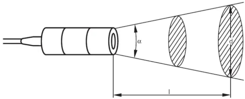
Calculation of diameter of visible area/sensing distance/angle of aperture
$$ \begin{array}{l} d = 2 \times I \times \tan \frac {\alpha}{2} + \varnothing \ I = 0. 5 \times \frac {d - \varnothing}{\tan \frac {\alpha}{2}} \ \end{array} $$
$$ \alpha = 2 \times \tan^ {- 1} \left(\frac {d - \varnothing}{2 \times I}\right) $$
$$ \begin{array}{l} \alpha = \text {a n g l e o f a p e r t u r e} \ \mathsf {l} = \text {s e n s i n g d i s t a n c e} \ d = d i a m e t e r o f v i s i b l e a r e a \ \varnothing = \text {l e n s d i a m e t e r} \ \end{array} $$
Sensing range diagram:
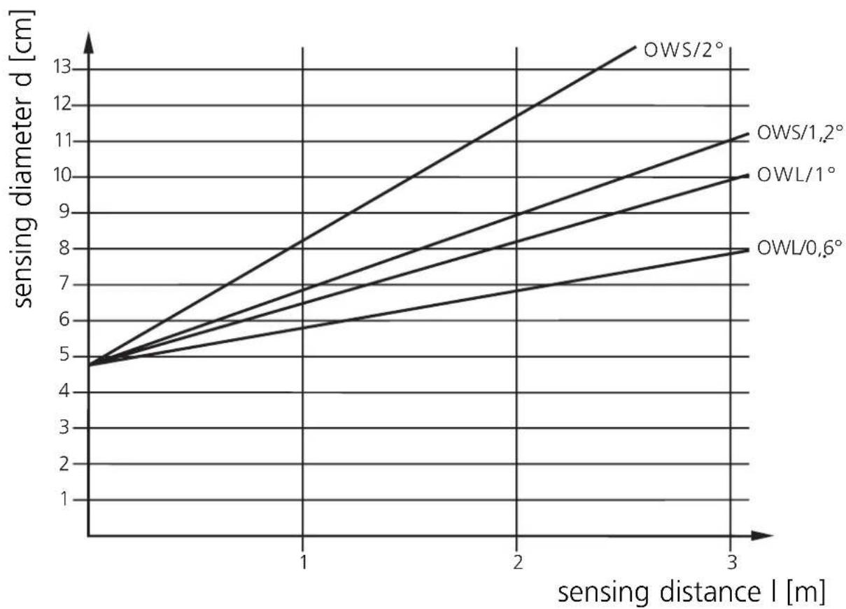
In the event of ranges of >5m radiation losses must be taken into account. The temperature of the object should therefore be much higher than the switching temperature of the sensor.
Electrical connection
Disconnect power, then connect the unit according to the wiring diagram.
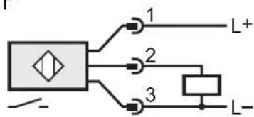
DC PNP

DC NPN
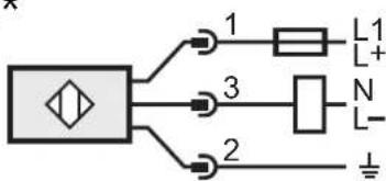
AC/DC*
Note: insert a miniature fuse according to the technical data sheet, if specified.
Recommendation: check the unit for reliable function after a short cirucit.
Core colours of ifm sockets: BN = brown, BU = blue, BK = black,
GN/YE = green/yellow.
*Output not short-circuit protected.
Short circuit can lead to immediate destruction of the unit.
Operation
Check the safe functioning of the sensor.
If in the application wrong switching occurs due to background radiation (e.g. ovens), use units with higher switching temperatures.
For applications in difficult environments (e.g. dust, vapour) or in the event of heat reflections of the environment use infrared heat sensors with a protective tube (order no. E20427).
If necessary, keep the optics clean by means of passing compressed air into the connection piece of the protective tube.
Brand : IFM
Model : OW5007
Category : Infrared sensor