050DCRJWFMC - Receiver CHAMBERLAIN - Free user manual and instructions
Find the device manual for free 050DCRJWFMC CHAMBERLAIN in PDF.
| Title | Description |
|---|---|
| Product type | Receiver for garage door motorization |
| Compatibility | Compatible with Chamberlain motorization systems |
| Operating frequency | 433 MHz |
| Number of channels | 2 channels to control multiple devices |
| Installation | Easy installation with provided instructions |
| Power supply | Powered by alternating current |
| Dimensions | Compact dimensions for discreet mounting |
| Maintenance | Regular checking of connections and component condition |
| Safety | Protection against overloads and short circuits |
| Warranty | Limited warranty according to manufacturer conditions |
Frequently Asked Questions - 050DCRJWFMC CHAMBERLAIN
User questions about 050DCRJWFMC CHAMBERLAIN
0 question about this device. Answer the ones you know or ask your own.
Ask a new question about this device
Download the instructions for your Receiver in PDF format for free! Find your manual 050DCRJWFMC - CHAMBERLAIN and take your electronic device back in hand. On this page are published all the documents necessary for the use of your device. 050DCRJWFMC by CHAMBERLAIN.
USER MANUAL 050DCRJWFMC CHAMBERLAIN
- Disconnect ALL electric and battery power BEFORE performing ANY service or maintenance.
CAUTION
To prevent damage to the receiver/logic board, DO NOT touch printed circuit board of replacement receiver/logic board during installation. ALWAYS wear protective gloves and eye protection when changing the battery or working around the battery compartment.

WARNING: This product can expose you to chemicals including lead, which are known to the State of California to cause cancer or birth defects or other reproductive harm. For more information go to www.P65Warnings.ca.gov.
NOTICE: This device complies with Part 15 of the FCC rules and Industry Canada's license-exempt RSSs. Operation is subject to the following two conditions: (1) this device may not cause harmful interference, and (2) this device must accept any interference received, including interference that may cause undesired operation.
Any changes or modifications not expressly approved by the party responsible for compliance could void the user's authority to operate the equipment.
This device must be installed to ensure a minimum 20 cm (8 in.) distance is maintained between users, bystanders and devices.
This device has been tested and found to comply with the limits for a Class B digital device, pursuant to part 15 of the FCC rules and Industry Canada ICES standard. These limits are designed to provide reasonable protection against harmful interference in a residential installation. This equipment generates, uses and can radiate radio frequency energy and, if not installed and used in accordance with the instructions, may cause harmful interference to radio communications. However, there is no guarantee that interference will not occur in a particular installation. If this equipment does cause harmful interference to radio or television reception, which can be determined by turning the equipment off and on, the user is encouraged to try to correct the interference by one or more of the following measures:
- Reorient or relocate the receiving antenna.
- Increase the separation between the equipment and receiver.
- Connect the equipment into an outlet on a circuit different from that to which the receiver is connected.
- Consult the dealer or an experienced radio/TV technician for help
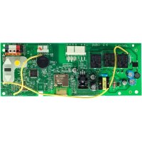
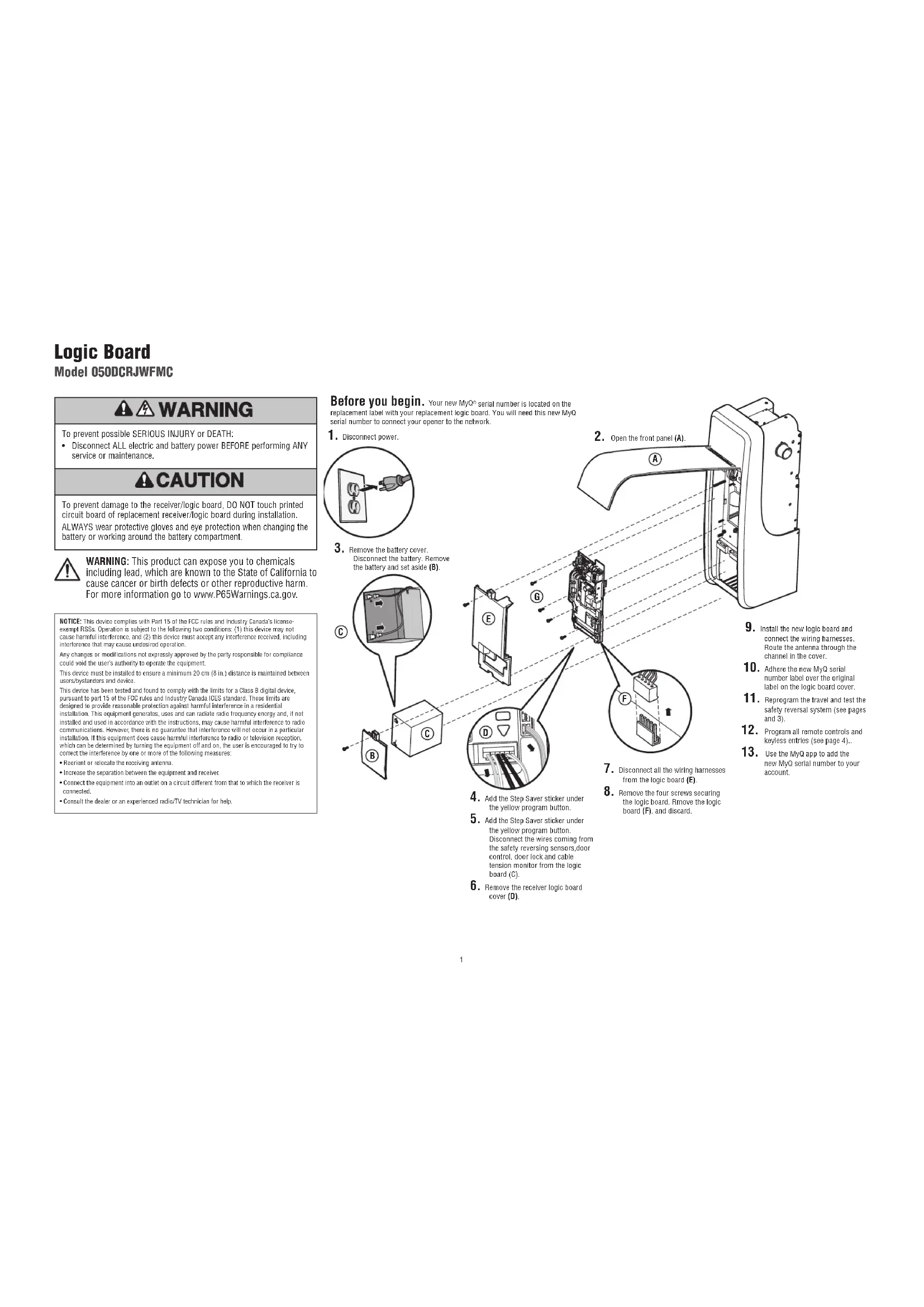
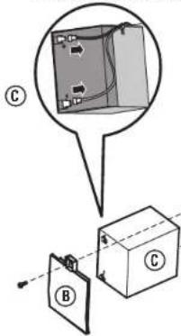
Before you begin. Your new MyQ serial number is located on the replacement label with your replacement logic board. You will need this new MyQ serial number to connect your opener to the network.
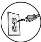
- Disconnect power.
- Remove the battery cover. Disconnect the battery. Remove the battery and set aside (B).
text_image
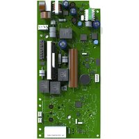
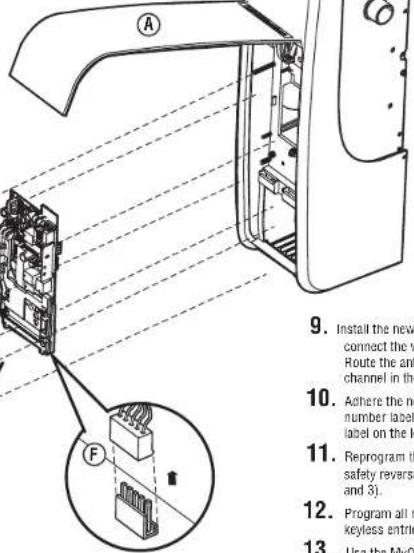
Diagram showing electrical wiring connections with labeled components A, B, and C, including a magnified inset view of the circuit.- Open the front panel (A).
text_image
9. Install the new connect the v Route the ant channel in the 10. Ashere the no number label label on the k 11. Reprogram th safety reversa and 3). 12. Program all r keyless entri 13. Use the MyO- Disconnect all the wiring harnesses from the logic board (E).
-
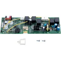
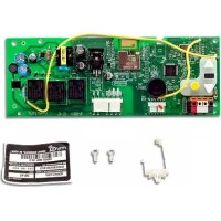
Remove the four screws securing the logic board. Remove the logic board (F), and discard.
-
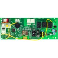
Install the new logic board and connect the wiring harnesses. Route the antenna through the channel in the cover.
- Adhere the new MyQ serial number label over the original label on the logic board cover.
- Reprogram the travel and test the safety reversal system (see pages and 31).
- Program all remote controls and keyless entries (see page 4)...
- Use the MyQ app to add the new MyQ serial number to your account.
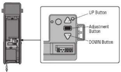
Adjustment
Program the Travel
- Press and hold the Adjustment Button until the UP Button begins to flash and/or a beep is heard. The Safety Reversing Sensors will be disconnected during the Program the Travel process.
- Press and hold the UP Button until the door is in the desired UP position.
- Once the door is in the desired UP position, press and release the Adjustment Button. The garage door opener lights will flash twice and the DOWN Button will begin to flash.
- Press and hold the DOWN Button, until the door is in the desired DOWN position.
- Once the door is in the desired DOWN position, press and release the Adjustment Button. The garage door opener lights will flash twice. Program the Travel is now complete. If the garage door opener lights flash 5 times, then programming has timed out and the Travel Limits have not been set. Please restart the Program the Travel process.
- To prevent damage to vehicles, be sure fully open door provides adequate clearance.
Automatic Force Setup
Once both the up and down positions have been manually set, the Safety Reversing Sensors will reconnect and become operational. Then, the opener will enter a force-sensing operation by automatically moving the door open and close. The garage door opener will sound an audible and visual alert before automatically opening and closing the door. The garage door opener will beep three times, confirming that the Automatic Force Setup completed successfully. Adjustment is complete.
If you hear one long beep after the door attempts to move, then the Automatic Force Set Up has not completed successfully. Please start over at step 1 of Program the Travel.
text_image
UP Button Adjustment Button DOWN Button1.2.
3.4.
WARNING
Without a properly installed safety reversal system, persons (particularly small children) could be SERIOUSLY INJURED or KILLED by a closing garage door.
- Incorrect adjustment of garage door travel limits will interfere with proper operation of safety reversal system.
- After ANY adjustments are made, the safety reversal system MUST be tested. Door MUST reverse on contact with 1-1/2" high (3.8 cm) object (or 2x4 laid flat) on floor.
CAUTION
To prevent damage to vehicles, be sure fully open door provides adequate clearance.
Adjustment
Test the Safety Reversal System
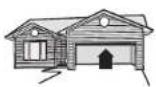
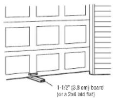
- With the door fully open, place a 1-1/2" (3.8 cm) board (or a 2x4 laid flat) on the floor, centered under the garage door.
- ress the remote control push button to close the door. The door MUST reverse when it makes contact with the board.
If the door stops but does not reverse:
- Review the installation instructions provided to insure all steps were followed;
- Repeat Program the Travel (see Adjustment Step 1);
- Repeat the Safety Reversal test. If the test continues to fail, call a trained door systems technician.
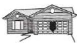
Test the Protector System®
- Press the remote control push button to open the door.
- Place the opener carton in the path of the door.
- Press the remote control push button to close the door. The door will not move more than 1".
The garage door opener will not close from a remote if the indicator light in either sensor is off (alerting you to the fact that the sensor is misaligned or obstructed).
Test Cable Tension Monitor
With the door fully closed, push on the front of the cable tension monitor. A click should be heard. If there is no click, the roller may be hitting the jamb and not allowing the switch to detect slack in the cable. Make sure the cable tension monitor is mounted flush with the wall and the roller is free from any obstructions.
If your cable tension monitor has been activated the UP and DOWN arrows will flash diagnostic code 3-5. will activate the garage door opener.
Test the Automatic Garage Door Lock
- With the garage door fully closed, the automatic garage door lock bolt should be protruding through the track.
- Open the garage door. The automatic garage door lock should retract before the garage door begins to move.
- Close the garage door. When the garage door reaches the fully closed position, the automatic garage door lock should automatically activate to secure the door.
Disengage the automatic garage door lock by sliding the manual release to the open position.
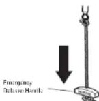
To Open the Door Manually
Disengage any door locks before proceeding. The door should be fully closed if possible. Pull down on the emergency release handle until a click is heard from the garage door opener and lift the door manually.
To reconnect the door to the garage door opener, pull the emergency release handle straight down a second time until a click is heard from the garage door opener. The door will reconnect on the next UP or DOWN operation.
text_image
1-1/2" (3.8 cm) board or a 2x4 laid flat)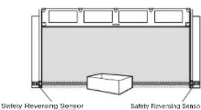
text_image
Safety Reversing Sensor Safety Reversing Sensor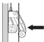

WARNING
Without a properly installed safety reversal system, persons (particularly small children) could be SERIOUSLY INJURED or KILLED by a closing garage door.
- Safety reversal system MUST be tested every month. - After ANY adjustments are made, the safety reversal system MUST be tested. Door MUST reverse on contact with 1-1/2" (3.8 cm) high object (or 2x4 laid flat) on the floor.
WARNING
Without a properly installed safety reversing sensor, persons (particularly small children) could be SERIOUSLY INJURED or KILLED by a closing garage door.
Programming
Remote Control
Your remote control has been programmed at the factory to operate with your garage door opener. If the remote does not work or you would like to program additional devices, follow the programming steps below.
Up to 40 Security+ 2.0 ^® remote controls can be programmed to the garage door opener. Older LiftMaster remote controls are NOT compatible. Programming can be done through the door control or the learn button on the garage door opener. To program additional accessories refer to the Instructions provided with the accessory or visit LiftMaster.com. If your vehicle is equipped with a Homelink ^® , you may require an external adapter depending on the make, model, and year of your vehicle. Visit www.homelink.com for additional information.
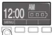
To add, reprogram, or change a 893LM remote control/877LM keyless entry pin using the door control
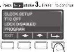
- Press the navigation button below 'MENU' to view the Features menu
- Use the navigation buttons to scroll to 'PROGRAM'.
- Select 'REMOTE' or "KEYPAD" to program from the program menu.
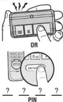
- Remote Control: Press the button on the remote control that you wish to operate your garage door.
- Keyless Entry: Enter a 4-digit personal identification number (PIN) of your choice on the keyless entry keypad. Then press the ENTER button.
The garage door opener lights will flash (or two clicks will be heard) when the code has been programmed. Repeat the steps above for programming additional remote controls or keyless entry devices. If programming is unsuccessful, program the remote using the learn button.
2
text_image
Press L... continue 3. Press to continue CLOCK SETUP TTC OFF LOCK DISABLED PROGRAM EXIT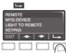
text_image
OR 0 or ENTER ? ? ? ? PINProgram a 893MAX remote control using the learn button on the garage door opener
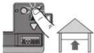
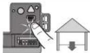
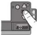
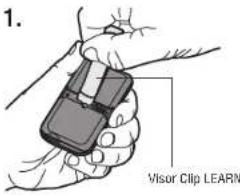
- Press and hold the program button on the remote control until the LED on the front of the remote control turns on.
- Press and release the remote control button you wish to use and then press any other button to exit programming.
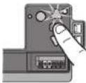
- Press and release the Learn button on the garage door opener. The Learn LED will light. Within 30 seconds...
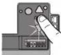
- Press the remote control button programmed in step 2 until the garage door opener light flashes or two clicks are heard.
To program other types of remote controls or keyless entries see the instructions included with the device or visit LiftMaster.com.
text_image
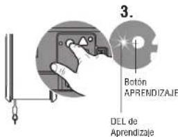
1. Visor Clip LEARN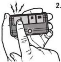
natural_image
Illustration of a hand holding a handheld electronic device with a button, emitting sound waves (no text or symbols visible)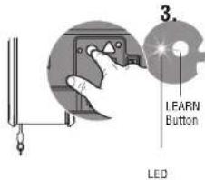
text_image
3. LEARN Button LED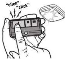
text_image
"click" "click"Add MyQ serial number to MyQ App
To program the WI-FI garage door opener to your network, refer to your owner's manual.
Carte logique
Modèle 050DCRJWFMC


AVERTISSEMENT
text_image
Diagram showing electrical circuit components with labeled parts B and C, including a magnified inset of a component.natural_image
Illustration of a hand holding a smartphone with a finger, emitting sound waves (no text or symbols visible)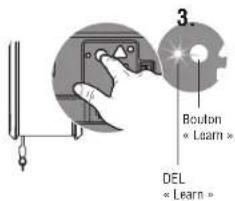
text_image
"click" "click"Tarjeta Lógica
Modelo 050DCRJWFMC
ADVERTENCIA
text_image
Diagram showing a device with labeled components (A, B, C) and an inset view of a component with internal wiring.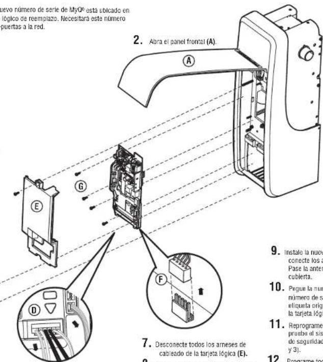
natural_image
Illustration of a hand holding a remote control device with vibration lines (no text or symbols)