Centro 160ie - Scooter MALAGUTI - Free user manual and instructions
Find the device manual for free Centro 160ie MALAGUTI in PDF.

| Technical Specifications | Engine: 160 cc, 4-stroke, liquid cooling |
|---|---|
| Power | 11.5 kW at 8,500 rpm |
| Transmission | Automatic, variator |
| Consumption | 3.5 L/100 km |
| Fuel tank capacity | 9 liters |
| Weight | 150 kg |
| Dimensions | Length: 2,050 mm, Width: 740 mm, Height: 1,400 mm |
| Usage | Designed for city and daily commuting |
| Maintenance | Oil change every 5,000 km, regular brake and tire checks |
| Safety | LED lighting, ABS braking system |
| General information | 2-year warranty, availability of spare parts |
Frequently Asked Questions - Centro 160ie MALAGUTI
User questions about Centro 160ie MALAGUTI
0 question about this device. Answer the ones you know or ask your own.
Ask a new question about this device
Download the instructions for your Scooter in PDF format for free! Find your manual Centro 160ie - MALAGUTI and take your electronic device back in hand. On this page are published all the documents necessary for the use of your device. Centro 160ie by MALAGUTI.
USER MANUAL Centro 160ie MALAGUTI
natural_image
Close-up of a silver electric scooter's front grille and headlight (no visible text or symbols)Indice
natural_image
Top-down schematic of a vehicle showing internal components and structural lines (no text or labels)Fig.1
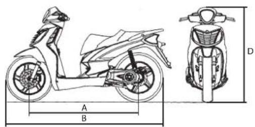
Dimensioni
passo (A-Fig.1) m.... 1,360
text_image
A Fig.4 B Fig.5natural_image
Line drawing of a scooter with labeled X and Y axes (no text or symbols on the diagram itself)| X | 100/80-16" 50P |
| Y | 120/80-16" 60P |

text_image
Diagram showing a car wheel switch mechanism and its labeled components A and B in the dashboard view.Fig.8Fig.7

malagmi IDEE IN MOTO
3.5 SERBATOIO LIQUIDO REFRIGERANTE
natural_image
Close-up of a mechanical device interior with labeled component A (no readable text or symbols)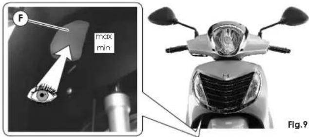
text_image
F max min Fig.93.6 BAULETTO ANTERIORE
natural_image
Close-up of a mirror with a labeled point P pointing to it, mounted on a desk lamp (no text or symbols beyond the label)Fig.12
3.8 VANO CASCO
natural_image
Technical illustration showing a car head assembly and a close-up of the helmet component (no text or symbols)3.9 GANCIO PORTABORSA
3.10 GANCIO ANTIFURTO
natural_image
Close-up of a car front panel with a black plastic connector and a white arrow pointing to a labeled component (no text or symbols visible)Fig.15

natural_image
Close-up of a white motorcycle's wheel and suspension system, showing mechanical components and a labeled section (A), with no visible text or symbols.Fig.16

Malas
IDEE IN MOTO
3.11 CRUSCOTTO
natural_image
Close-up of a silver scooter's front wheel and side-mounted motors (no visible text or symbols)Fig.17
3.11.1 SPIA ANOMALIA ELETTRICA / SERVICE
text_image
A B 3 2 1 Fig.18COMANDO SINISTRO (Fig.19)
text_image
Fig.20 Fig.213.15 ATTREZZATURE IN DOTAZIONE
natural_image
Close-up of a mechanical component with a highlighted section and arrow pointing to a detail (no visible text or symbols)
text_image
A B C D E Malawi 08609600Fig.22

malagmi IDEE IN MOTO
3.16 CAVALLETTO CENTRALE
natural_image
Mechanical assembly diagram of a scooter showing wheel, brake, and suspension components (no text or symbols)
Malagmi IDEE IN MOTO
Norme per l'uso
4.1 CONSIGLI
natural_image
Mechanical assembly diagram showing components labeled A and B, no readable text or symbols presentFig.24

text_image
Technical diagram showing mechanical assembly with numbered parts labeled 1, 2, and 3Fig.26 Fig.27
text_image
spia o e S MIN MIN B A Fig.28text_image
- MAX - MINFig.29

Malagami IDEE IN MOTO
5.7 TABELLA LUBRIFICANTI

natural_image
Close-up of a mechanical component with a labeled section (C) and a tool inserted, no visible text or symbols.Fig.30
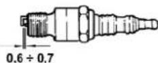
Fig.31
5.9 REGOLAZIONE AMMORTIZZATORI POSTERIORI
natural_image
Close-up of a scooter's wheel and suspension system with labeled component (R), no visible text or symbols beyond the label.Fig.32

natural_image
Mechanical assembly diagram showing a wheel, brake disc, and gear mechanism (no text or symbols)Fig.33
natural_image
Mechanical assembly diagram showing a brake caliper and wheel assembly with an eye indicator (no text or labels)Fig.34

text_image
MIN. 2mm Fig.355.14 LUCI
5.14.1 FARO ANTERIORE
text_image
A B R Fig.36


malagmi IDEE IN MOTO
natural_image
Front view of a scooter's head and front grille, labeled with 'C' and figure number Fig.37 (no text or symbols on the body)
Malami
IDEE IN MOTO
text_image
E P W S B WFig.38
natural_image
Close-up of a car interior showing engine compartment and dashboard (no visible text or symbols)
text_image
S EFig.40Fig.39


Malagmi IDEE IN MOTO
5.14.4 FANALINO TARGA
• Luce targa (C-Fig.41)
Lampada 12V - 5W (W5W)
natural_image
Technical illustration of a car's front wheel assembly with labeled component (C), no readable text or symbols beyond labelsnatural_image
Simple line drawing of a battery with a switch and a labeled component (no text or symbols)Fig.44 Fig.45 Fig.46 Fig.47

natural_image
Close-up of a mechanical component with labeled parts S and V, showing internal structure and mounting base (no readable text or symbols beyond labels)
natural_image
Close-up of a mechanical component with labeled parts (C), showing internal structure and wiring (no readable text or symbols)
natural_image
Close-up of an electronic device showing internal components and wiring (no visible text or symbols)
Malagmi IDEE IN MOTO
natural_image
Top-down line drawing of a car viewed from above, showing structural components and roof (no text or symbols)AB0:1
Abmessungen
Radstand (A-Abb.1) m.... 1,360
natural_image
Line drawing of a scooter with labeled X and Y axes (no text or symbols on the diagram itself)| X | 100/80-16" 50P |
| Y | 120/80-16" 60P |

text_image
T.W.I. 2 mm Fig.6DRUCK
| bar (psi) | |||
| X | 2.0(29.0) | 2.0(29.0) | 2.1(30.5) |
| Y | 2.2(31.9) | 2.3(33.4) | 2.3(33.4) |

natural_image
Diagram of a hand using a tool to lift a circular component, showing motion direction (no text or symbols)Abb.7
text_image
A BAFig.8Fig.7

Malas
IDEE IN MOTO
natural_image
Close-up of a mechanical device with labeled component A, showing internal components and no readable text or symbols.
text_image
F max min Aldg.9

text_image
1 2 3 4 5 6

malagtt IDEE IN MOTO
3.6 VORDERES FACH
natural_image
Close-up of a mirror with a labeled point P pointing to it, mounted on a desk lamp (no text or symbols beyond the label)Abig.12
3.8 HELMFACH
natural_image
Close-up of a car helmet being inserted into a vehicle's hood, with a close-up inset showing the component (no visible text or symbols)Abb.14
3.9 GEPÄCKHAKEN
natural_image
Close-up of a car front panel with a labeled connector (G), showing internal components and mounting points (no text or symbols beyond label)Abig.15
natural_image
Mechanical assembly diagram showing a car wheel with suspension components and labeled section A (no text or symbols beyond label)
Malaga
IDEE IN MOTO
3.11 ARMATURENBRETT
natural_image
Close-up of a silver electric scooter's front wheel and side-mounted motors (no visible text or symbols)AFig.17

natural_image
Diagram of a hand operating a mechanical component with a curved arrow indicating rotation (no text or symbols present)Abb.21
natural_image
Mechanical assembly diagram of a scooter showing wheel, brake, and mounting bracket (no text or symbols)
Malagmi IDEE IN MOTO
natural_image
Mechanical assembly diagram showing components labeled A and B, no readable text or symbols presentA6ig.24

text_image
Technical diagram showing mechanical assembly with numbered parts for identificationAbb.27Abb.26
text_image
S MIN MIN B A AFig.28text_image
- MAX - MINABB.29

Malagami IDEE IN MOTO
5.7 SCHMIERMITTELTABELLE

natural_image
Close-up of a mechanical component with a labeled section (C) and a tool inserted, no visible text or symbols.Abb.31
natural_image
Close-up of a scooter's wheel and suspension system, showing mechanical components and a labeled part (R) (no text or symbols beyond label)Alig.32

natural_image
Mechanical assembly diagram showing a wheel, brake caliper, and eye mechanism (no text or symbols)Apg.33

natural_image
Mechanical assembly diagram showing a brake caliper and wheel assembly (no text or labels)A19.34

text_image
MIN. 2mm AFig.35
Malacan
IDEE IN MOTO
5.14 SCHEINWERFER
Halogenlampe 12V - 60/55W (H4)
• Standlicht (B-Abb.36)
Lampe 12V - 5W (W5W)
Orange Lampe 12V - 10W (RY10W)
AUSWECHSELN DER LAMPEN

natural_image
Front view of a scooter's head and front grille (no text or symbols visible)
Malami
IDEE IN MOTO
Lampe 12V - 5W (W5W)
- Stopplicht (S-Abb.38)
Lampe 12V - 10W (R10W)
• Hinterer Blinker (E-Abb.38)
Lampe 12V - 10W (R10W)

text_image
E P W S B W AIAFig.38


AUSWECHSELN DER LAMPEN
natural_image
Interior view of a car showing engine compartment and dashboard (no visible text or symbols)
text_image
S EFig.40Fig.39


Malagmi IDEE IN MOTO
natural_image
Technical illustration of a car's front wheel assembly with labeled component (C), showing engine, battery, and tire components (no readable text or symbols)AUSWECHSELN DER LAMPEN
natural_image
Simple line drawing of a battery with a switch and a labeled component (no text or symbols)Afbp.444 Fig.45 Flg.46 Flg.47
natural_image
Close-up of a mechanical component with labeled parts S and V, showing internal structure and mounting base (no readable text or symbols)Abb.45

natural_image
Close-up of a mechanical component with labeled parts (C), showing internal structure without any readable text or symbols.Abb.46
natural_image
Close-up of an electronic device showing internal components and wiring (no visible text or symbols)Abb.47

Malagmi IDEE IN MOTO
1.1 Contents of the manual 3
1.2 Notes for easy consultation....3
1.3 Warnings for use 4
2. SPECIFICATIONS....5
3. GETTING TO KNOW YOUR VEHICLE....7
3.1 Main components....7
3.2 Identification data: Chassis n° / engine n°......8
3.3 Tires....9
3.4 Fuel tank 10
3.5 Coolant tank....11
3.6 Front compartment....12
3.7 Rear-view mirrors 13
3.8 Helmet compartment 13
3.9 Luggage hook 14
3.10 Anti-theft hook 14
3.11 Instrument board....15
3.12 Handlebar controls 17
3.13 Key switch 18
3.14 Handlebar lock....18
3.15 Owner's tool kit 18
3.16 Centre stand 19
4. OPERATING INSTRUCTIONS .....20
4.1 Suggestions 20
4.2 Engine break-in....20
4.3 Checks before use 21
4.4 Starting the engine....21
4.5 Setting off 23
4.6 Braking 23
4.7 Stopping the engine 23
4.8 Safety information and important riding points.....24
5. ROUTINE MAINTENANCE ......26
5.1 Maintenance 26
5.2 Maintenance table.... 27
5.3 Transmission oil 28
5.4 Engine oil 29
5.5 Front/rear brake oil 31
5.6 Coolant 32
5.7 Lubricant table 33
5.8 Spark plug 34
5.9 Adjusting rear shock absorbers....35
5.10 Adjusting engine idling speed 35
5.11 Throttle free play adjustment 35
5.12 Adjusting brake levers 36
5.13 Checking pads and discs of front/rear brakes......36
5.14 Light 37
5.15 Fuses....41
5.16 Battery (12v - 9ah) 42
5.17 Troubleshooting 44
5.18 Storage 45
5.19 Cleaning....45
6. ACCESSORIES....46


text_image
1 2 3 4 5 6

malagmi IDEE IN MOTO
Introduction
- MALAGUTI Spa makes on-going efforts to perfect all its vehicles as well as the manuals supplied with them. Please carefully read this Owner's Manual before using your new vehicle. If you decide to sell it, you MUST hand this manual, its warranty and log book over to the new owner.
- MALAGUTI SpA reserves the right to modify its models without notice; therefore, kindly check if the vehicle meets your expectations before purchasing it.
- All MALAGUTI vehicles are designed and built with their common use in mind: therefore, any special use of MALAGUTI vehicles is excluded unless expressly approved in writing by MALAGUTI SpA.
- The vehicle observes the emission limits provided for by the European directive for motorcycles.
- Exclusively refuel your vehicle with: UNLEADED PETROL.
The muffler irradiates heat even after the engine has been turned off.
We therefore recommend you to carefully read the following instructions:
- Always allow the engine and muffler to cool down before any maintenance operation, in order to avoid hot surfaces.
• Make sure you do not park nor stop your vehicle on grass, paper, dead leaves or other easily inflammable materials. - The passenger should get on and off the vehicle from the opposite side of the muffler, in order to avoid surfaces.
ALWAYS RESPECT THE HIGHWAY CODE AND .... RIDE WITH CAUTION

For Spare Parts and Accessories, always contact an Authorised MALAGUTI Service Centre.

Malas
IDEE IN MOTO
1.1 CONTENTS OF THE MANUAL
1) INTRODUCTION

Introduction and instructions for use of the manual.
2)

SPECIFICATIONS
Technical features of the vehicle.
3)

GETTING TO KNOW YOUR VEHICLE
Description of the main parts of the vehicle, of the equipment on board and of the control devices.
4)

OPERATING INSTRUCTIONS
Checks before use and hints. Engine break-in. Using the vehicle. Safety information and important riding points.
5)

MAINTENANCE
Periodic checks to be carried out by Authorised MALAGUTI Service Centres. Electrical components installed on board. Troubleshooting. Recommendations for storage of the vehicle and cleaning.
6)

ACCESSORIES
List of available accessories
IMPORTANT! For all maintenance, repair or accessory installation work, contact an Authorised MALAGUTI Service Centre.
1.2 NOTES FOR EASY CONSULTATION

ATTENTION! Texts bearing this symbol contain important safety information. Failure to observe these instructions can lead to serious damage.

Important! Texts bearing this symbol contain important information about integrity of the vehicle.

Note. Texts bearing this symbol contain further information.

Malaguti. The operation described must be entrusted to an Authorised MALAGUTI Service Centre.

Operations to be exclusively carried out while the engine is off.

For '125ie' version only

For '160ie' version only


malagmi IDEE IN MOTO
1.3 WARNINGS FOR USE
- The User must be in possession of the technical approval certificate (Log Book), insurance, road fund certificate and a driving licence complying with the laws in force.
- The identification plate must be applied to vehicle.

A helmet must be worn at all times (helmet approved by ECE/ONU).
- Always comply with the highway code: signs, of way, pedestrian crossings, speed limits, overtaking prohibitions, etc.
- Any tampering with the engine or other parts in order to increase speed or power is forbidden by law.

Infringements are punished by law by penalties that include confiscation.
- Using the vehicle for sporting purposes on circuits or private land voids the warranty and exonerates MALAGUTI SpA from any liability for harm to things or persons as the User has been warned that such use constitutes an improper use of the vehicle.
- Bearing in mind the above we strongly advise that any modifications made to make the vehicle suitable for sporting use be carried out by expert technicians on their own direct responsibility and remind you that after such modifications your vehicle may no longer be authorised to circulate on the public highway.
the In countries in which the law permits the carrying of a passenger, make sure that the passenger wears an approved helmet and do not carry children or persons who are unable to remain seated in the saddle unassisted.
Right Do not carry passengers unless they have first been warned and instructed on how they must behave whilst the vehicle is travelling.

Any work on the vehicle performed by persons who are not part of the network of Authorised MALAGUTI Service Centres may change the vehicle's original safety characteristics and may lead the retailer who sold the vehicle to refuse to perform work under warranty.
Specifications
MALAGUTI SpA reserves the right to modify the specifications at any time without prior notice.
text_image
A B D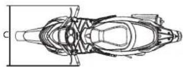
natural_image
Top-down schematic of a vehicle showing internal components and structural lines (no text or labels)Fig.1
Dimensions
Wheel base (A-Fig.1) m.... 1,360
Max. length (B-Fig.1) m 2,050
Max.width(C-Fig.1)m....0,730
Max. height (D-Fig.1) m.... 1,180
Kerb weight kg 140
Max. load with rider, passenger and luggage kg..... 180
Capacity
Engine oil cm3 1000*
Transmission oil cm3 150*
Fuel tank capacity (reserve) L 8.2* (3.0*)
Engine: single-cylinder, two-valve - 4-stroke
Type .... MALAGUTI 01
MALAGUTI 02
Cylinders ....1
Bore x stroke mm 52.4 x 57.8
∅ 58.0 × 57.8
Capacity cm3 125
153
Compression ratio 10.6 :
11.3 :
Cooling....liquid
Starting system ....electric starter
Greasing system....wet sump
Spark plug
Type NGK DPR7EA9
Transmission
Primary: automatic speed variator with V-belt.
Final: with gears.
Automatic dry centrifuge clutch.
* Indicative Value


malagmi IDEE IN MOTO

text_image
1 2 3 4 5 6Fuel system
electronic injection with electrical fuel pump.
Fuel: unleaded petrol.
Ignition
Digital.
Brakes
Front brake: disk type, ∅ 245 mm hydraulic calipers with double piston ∅ 25 mm. Rear brake: disk type, ∅ 220 mm hydraulic calipers with piston ∅ 34 mm.
Chassis
Made of steel pipes with a high resistance.
Suspensions
Front: hydraulically controlled fork ∅ 33 mm - stroke 88 mm. Rear: oscillating motor with double hydraulic shock absorber - stroke 74 mm.
Battery
12V, 9Ah, maintenance-free.
Tires
Front: 100/80 - 16 50P (tubeless) Rear: 120/80 - 16 60P (tubeless)

It is possible to use tires with load and speed indexes that are higher than or identical to those indicated. It is however necessary for the speed indexes to be identical for both tires.


Malacat
IDEE IN MOTO
Getting to know your vehicle
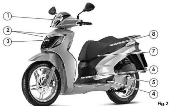
3.1 MAIN COMPONENTS
N. Description Page
1 Headlight 37
2 Front turn indicator 38
3 Radiator -
4 Passenger footboard -
5 Centre stand 19
6 Battery 42
7 External helmet fastener 13
8 Helmet compartment 13
9 Tail lamp 39
10 Number plate light 40
11 Number plate holder
12 Anti-theft hook 14
13 Muffler
14 Hook for bag 14
15 Coolant tank 11
16 Front compartment 12
17 Switch with key 18
18 Mirror 13
19 Instrument board 15
20 Protection fuses 41
21 Twin seat
22 Fuel tank cap 10
23 Passenger handles
text_image
① ② ③ ⑧ ⑦ ⑥ ⑤ ④ Fig.2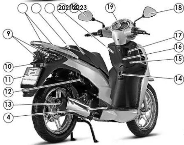
text_image
2021 22 23 9 10 11 12 13 4 15 16 17 18 19 20Fig.3

Malagmi IDEE IN MOTO
3.2 IDENTIFICATION DATA: CHASSIS N° / ENGINE N°
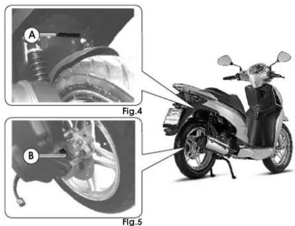
- The vehicle's identification number (VIN) (A-F) is located on the rear side of the chassis, under the helmet compartment.
• Engine identification data are visible on the engine crankcase (B-Fig.5).
3.2.1 ANTI-TAMPERING PLATE FOR 125 cc. MODELS ONLY
1.4 Ananti-tamperingplate, bearing all vehicle identification data required by Directive 97/24/CE Chap. 7, is fitted inside the helmet compartment. If you have the helmet lecompartment replaced, make sure the plate is fitted too.
Altering identification data will be punished according to the law.
- When ordering spare parts, also quote the vehicle identification data.
text_image
A Fig.4 B Fig.5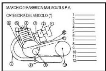
text_image
MARCHIO DI FABBRICA MALAGUTIS P.A. CATEGORIA DEL VEICOLO (°) 1 2 3 4 5 6 7 8 9 10 11 12
Malagmi IDEE IN MOTO
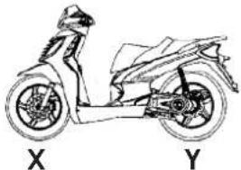
3.3 TIRES
Type: Tubeless (without inner tube)
natural_image
Line drawing of a scooter with labeled X and Y components (no text or symbols on the diagram itself)| X | 100/80-16" 50P |
| Y | 120/80-16" 60P |

It is possible to use tires with load and speed indexes that are higher than or identical to those indicated.

It is however necessary for the speed indexes to be identical for both tires. USE ONLY HOMOLOGATED TIRES.
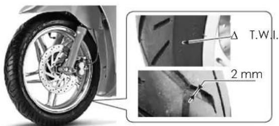
Check the tire conditions (before every journey): are broken (cracked) or cut, have them replaced as soon as possible.
"T.W.I." marks are provided all around the tire side walls. These correspond to tire wear indicators, which are situated in the tire's tread; if there is no difference between the thickness of these indicators and the tread depth itself, the tire must be replaced.

Minimum tread depth (front and rear) is 2 mm (Fig.6).
text_image
T.W.I. 2 mmFig.6
PRESSURE
| bar (psi) | |||
 X X | 2.0(29.0) | 2.0(29.0) | 2.1(30.5) |
| Y | 2.2(31.9) | 2.3(33.4) | 2.3(33.4) |


The pressure of tires must be adjusted while the tire is at ambient temperature.
Pressure differing from that indicated can lead to higher fuel consumption, irregular wear of the tire, impaired vehicle performance and riding conditions.

Malagmi IDEE IN MOTO
3.4 FUEL TANK
To access the fuel tank, proceed as follows:
- Place the vehicle on the centre stand.
• Take the ignition key out of the switch block and insert it into the lock on the left hand side of the seat (Fig.7). - Open seat by turning ignition key clockwise (B-Fig.8).
- Remove the cap (A-Fig.8) and fill the tank.
- After refuelling, immediately remove any possible traces of fuel from the vehicle body, since fuel may deteriorate the vehicle's outer surfaces.
- The quantity of fuel, as well as a low fuel level, are displayed by the corresponding indicator on the right hand side of the instrument board (7-Fig.17).
• Use UNLEADED PETROL.

Petrol is extremely inflammable; avoid approaching the fuel filler - also during filling - with lit cigarettes or naked flames (for instance matches). Danger of fire!
| FUEL TANK |
| TOTAL TANK CAPACITY 8.2* |
| RESERVE 3.0* |
* Indicative value in litres
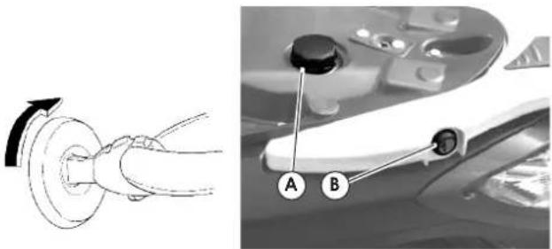
text_image
Diagram showing a car wheel switch mechanism and its labeled components A and B in the dashboard.Fig.8Fig.7

malagmi IDEE IN MOTO
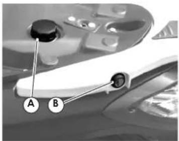
3.5 COOLANT TANK
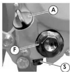
To gain access to the engine coolant tank, open the front compartment using the key and remove the protective plastic cover (A-Fig.9).
Owing to the particular position of the tank, you can check the level of coolant with respect to the "MIN" and "MAX" notches by checking through the sight glass located under upper fairing on the right hand side (F-Fig.9) (as described in chap.5.6 of this manual).

Use the coolant prescribed in this manual - or one having identical characteristics - for any topping up.

Never unscrew the tank cap when the engine is warm, so as to avoid burnings. Do not top up with water, except in emergency situations, and in this case, have the entire contents of the tank replaced with a suitable product as soon as possible.
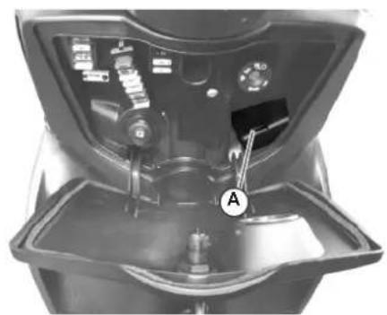
natural_image
Interior view of a mechanical device with labeled component A (no readable text or symbols)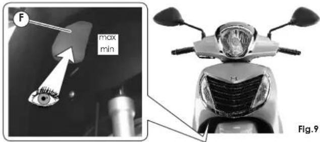
text_image
F max min Fig.9
malagmi IDEE IN MOTO
3.6 FRONT COMPARTMENT
This is located at the centre of the lower fairing. It features a lock that can be opened by turning the ignition key clockwise (A-Fig.10) and contains:
- the fuses of the electrical system (B-Fig.10) and relative spare fuses (F-Fig.10) (see chap.5.15).
• The coolant tank (S-Fig.10) (see chap.3.5). - The 12V socket fig.(11) can be used to connect a battery charger for maintenance-free batteries that can keep the battery charged in the event of long-term storage of the vehicle.
Remember to refit the socket cap after use to prevent foreign matters from causing short-circuits or other unexpected consequences.

Do not store heavy objects or temperature sensitive items (lighters, matches, inflammable liquids, perishables goods, etc...) inside the compartments. It is advisable not to leave any documents or valuables inside these compartments.
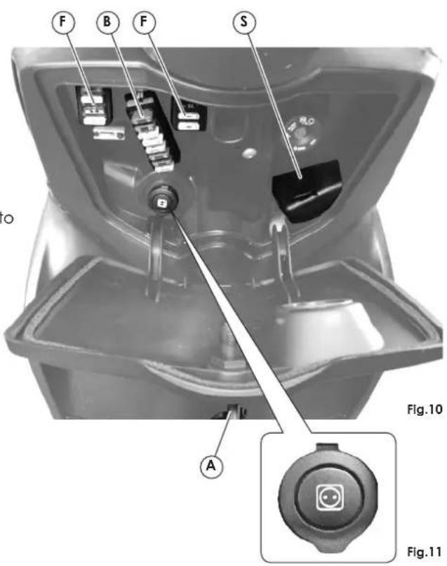
text_image
F B F S Fig.10 A Fig.11
Malas
IDEE IN MOTO
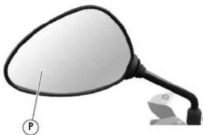
3.7 REAR-VIEW MIRRORS
The left and right rear-view mirrors must be fi handlebar, in particular in their seats, and firmly secured in place.
Adjust the visual angle of the mirror, while you are sat in riding position on the vehicle in riding order, by turning the mirror until you obtain the best conditions of visibility (P-Fig.12).
The objects that are visible through the mirrors are actually closer than they seem.

Do not adjust rear-view mirror while driving. Always wait to stop at a traffic light, for
natural_image
Close-up of a mirror with a labeled point P pointing to it, next to a small object (no text or symbols on the mirror itself)Fig.12
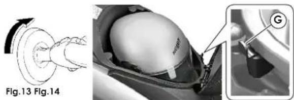
3.8 HELMET COMPARTMENT
This is located under the seat. The helmet compartment can contain a Jet helmet, positioned as shown in Fig.14. Some types of helmet may not fit into the compartment. Before purchasing helmet, make sure it fits into the compaftr
- To gain access to the helmet compartment, put the vehicle on its stand; take the ignition key out of the switch block and insert it into the lock on the left hand side of the seat (Fig.13).
- On the front left edge of the helmet compartment, you will find a hook for another helmet (example.

The helmet compartment can be used to carry light objects. They shall be stored in such a way as not to compromise the vehicle's stability while riding. Do not store objects which are not temperature resistant (lighters, inflammable liquids, perishable goods, etc.). Do not leave documents or valuables inside the helmet compartment.
text_image
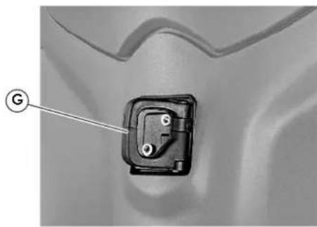
Fig.13 Fig.14 G3.9 LUGGAGE HOOK
The luggage hook (G-Fig.15) is located at the centre of the lower fairing. It must be used only for holding light and stable loads.

Never use this hook for loads that alter your riding position or put the vehicle's stability at risk. The load must never protrude from the sides of the vehicle.
natural_image
Close-up of a mechanical component with a labeled section (G), no visible text or symbols beyond the label.Fig.15
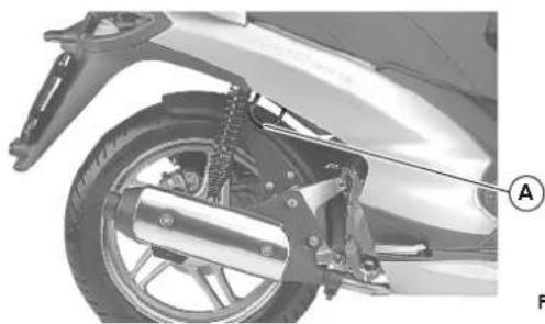
3.10 ANTI-THEFT HOOK
It is on the bottom right side (A-Fig.16) and is integral with the chassis, allowing a firm grasp to any external element (column, post, etc.) by means of an anti-theft chain that you can purchase from an Authorised MALAGUTI Service Centre.

Do not hook the chain to mobile structures and/or parked vehicles.
Always check that the vehicle is steady while it is 'firmly fixed'.
Never lay the anti-theft chain (usually fitted into plastic hose) on the muffler or on other hot part. Never ride if the anti-theft chain has not been previously stored inside the helmet compartment or inside the rear top case, if provided.
After turning the engine off, be careful not to touch the hot muffler in order to avoid burnings.
natural_image
Close-up of a white motorcycle wheel assembly with visible brake and suspension components (no text or symbols)Fig.16

Malas
IDEE IN MOTO
3.11 INSTRUMENT BOARD
1) Analogue instruments, Speedometer
This indicates the current speed in kmh or mph.
2) Odometer
This indicates the total distance travelled in kmh.
3) Green turn indicator light
4) Blue high beam indicator light
5) Orange electrical fault / SERVICE warning light For more information see par. 3.11.1.
6) Red coolant temperature warning light The warning light comes on to indicate that the coolant temperature is too high.
7) Fuel level indicator
This displays the level of fuel in the tank. The red zone means that reserve level has been reached.
8) Coolant temperature indicator The red zone means that temperature of the coolant is too high. The blue zone means that temperature of the coolant is low.
9) Digital clock
For information about use and setting, see par. 3.11.2.

text_image
Labeled diagram of a refrigerator interior showing numbered parts and digital display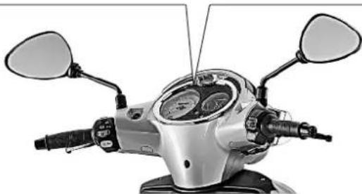
natural_image
Front view of a silver electric scooter's head and front wheel assembly (no visible text or symbols)Fig.17
3.11.1 ELECTRICAL FAULT / SERVICE WARNING LIGHT
When the key is turned to position, without starting the engine, the orange light (along with the red light) come on for a few seconds to test operation. In normal conditions, after the test cycle, the light goes off. If the light remains on (steadily lit and/or either of the following situations may be present:
- Electrical Fault (alternate short and long flash) this means that the vehicle's electrical equipment is not in working order. Have your vehicle checked as soon as possible by an Authorised MALAGUTI Service Centre. - SERVICE (15 short flashes): this means that maintenance must be performed (see Maintenance Table in chap.5.2). Contact an Authorised MALAGUTI Service Centre.

In both cases, as well as during scheduled maintenance work, the Authorised MALAGUTI Service Centre will reset the SERVICE signal after performing the necessary work.

SERVICE signal frequency, which is indicated by the light, may not correspond to the indications provided in the Maintenance Table. Frequency of scheduled maintenance, in fact, depends on how and where the vehicle is used, etc. In these cases, contact an Authorised MALAGUTI Service Centre.
3.11.2 DIGITAL CLOCK
To select clock functions, proceed as follows:
- reading date and month press top button once (time will appear automatically after a few seconds).
reading seconds
press top button twice; to resume the initial s): configuration, press the button again.
To set the time or date, use the two buttons of the dial, starting from time display mode.
- setting month
schedule press the bottom button twice and select the correct number with the top button.
- setting date
press the bottom button 3 times and select the correct number with the top button.
- setting time
press the bottom button 4 times and select the correct number with the top button.
- setting minutes
press the bottom button 5 times and select the correct number with the top button.
Press the bottom button again to return to time display mode. If you have changed your settings, save them by pressing the top button.

Malagami IDEE IN MOTO
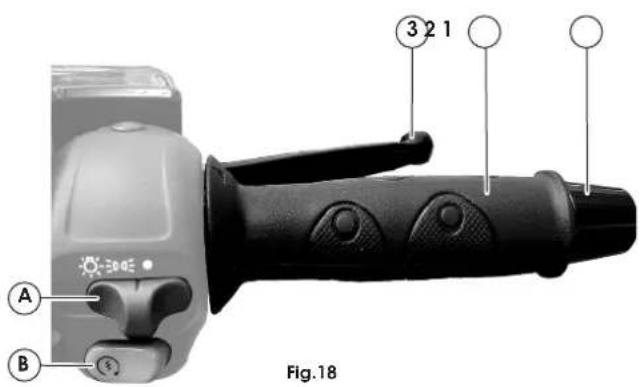
3.12 HANDLEBAR CONTROLS
RIGHT HAND CONTROL (Fig.18)
1) Counterweight
2) Throttle grip
3) Front brake lever
A) Light switch:
right = OFF
centre = parking and instrument board lights
left = low/high beam lights
B) Electric starter button.
text_image
A B 3 2 1 Fig.18LEFT HAND CONTROL (Fig.19)
1) Rear brake lever
2) Counterweight
3) Horn button.
4) Turn indicator switch.
5) Button for turning off indicator lights
6) Light switch:
ED high beam
D low beam

text_image
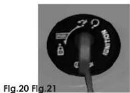
Fig.193.13 KEY SWITCH
This switch (Fig.20) controls the ignition circuit, the handlebar lock.

ignition disabled (the key can be removed).

'ready to start' position (the key cannot be removed)
handlebar lock activated (ignition is disabled. The key can be removed) (chap.3.14).
3.14 HANDLEBAR LOCK
Activation
With the handlebar turned to the left, push the key in and turn it counter-clockwise (Fig.21).
Disengagement
Turn the key counter-clockwise.
text_image
Fig.20 Fig.21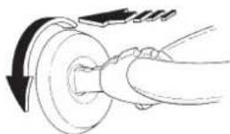
natural_image
Diagram of a mechanical component with a rotating shaft and curved arrow indicating rotation (no text or symbols)3.15 OWNER'S TOOL KIT
The vehicle is equipped with a tool bag placed under the seat, in which you can find the following tools (Fig.22):
A Spark plug pipe (to be used with an adjustable spanner)
B Handle for inserts
C Double insert screwdriver / allen wrench (to be used with handle "B")
D Adjustable spanner
E Shock absorber adjustment wrench
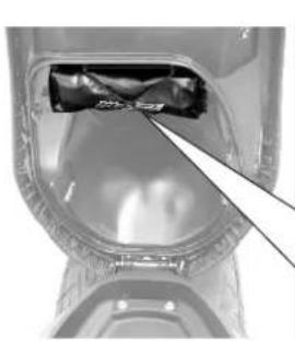
natural_image
Close-up of a mechanical component with a highlighted section and arrow pointing to a detail (no visible text or symbols)
text_image
A B C D E Malzzi 08609600Fig.22

malagmi IDEE IN MOTO
3.16 CENTRE STAND
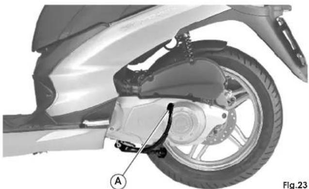
The centre stand position is not electronically controlled; therefore you can turn the engine on while the vehicle is parked. To place the vehicle on the stand, push the pin (A-Fig.23) and raise the vehicle using the rear grab rail.

During this manoeuvre, hold the vehicle in place to prevent it falling over.

When the stand is down, do not sit on the vehicle.
natural_image
Mechanical assembly diagram of a scooter showing wheel, brake, and mounting bracket (no text or symbols)


malagmi IDEE IN MOTO
Operating instructions
4.1 SUGGESTIONS
The condition of a vehicle is the owner's responsibility. Vital functions of the vehicle can start to d quickly and unexpectedly, even if the vehicle remains unused (for instance, as a result of exposure to the elements). Any damage, fluid leakage or loss pressure could have serious consequences.
Therefore, check all main vehicle components with great care before use.

Important!
After a long ride at high RPM, when you stop the vehicle do not turn the engine off immediately but let it run idle for about 30 seconds.
4.2 ENGINE BREAK-IN
Good running in is essential to ensure that the life of engine, transmission and moving parts is sufficiently long.
During the first 1000 km (625 miles):
- Avoid using full throttle and maintaining a constant speed for a long time.
• Do not use the vehicle over 80% of the top speed.
After the first 1000 km (625 miles), increase speed progressively, as established by the limits envisaged by rules in force.

Both during and after running in, use only UNLEADED PETROL.

Malacat
IDEE IN MOTO
4.3 CHECKS BEFORE USE
| PART CHECK | |
| Fuel Enough fuel | |
| Transmission engine oil | Level within limits specified. Check leaks |
| Tires Check pressure/wear/damage. | |
| Nuts, screws, bolts | Check tightness |
| Steering | Free movement from one end to the other. |
| Front/Rear brakes | Working properly and not worn; if necessary, adjust or replace |
| Throttle | Operation should be smooth, if necessary lubricate or adjust |
| Lights and indicators | Proper working conditions |
| Coolant | Presence of coolant or possible leakages. |
| Stand | Operation of stand and springs |
| Loads | Make sure loads and accessories (e.g. rear case) are firmly secured to v |

Checking takes just a few minutes, but your safety and that of other people is extremely important. If you do not have time or prefer to make some closer checks, apart from the essential maintenance checks listed in section 5 of this manual, please contact an Authorised MALAGUTI Service Centre.
4.4 STARTING THE ENGINE
Before pressing the ignition button, pull the front or rear brake lever and keep it pulled to start the engine, since this lever acts on a special ignition consent switch.

The automatic transmission runs the rear wheel, even when the throttle lever is operated gently. Gradually release the brake after starting and use the throttle with care.

Never start the engine in a closed area. Exhaust fumes are poisonous.

If the tank is empty, do not operate the «START» button and do not turn the key «ON» as this would damage the injection system.

If the engine does not start, release the ignition switch, wait a few seconds, then try again. Do not operate the ignition system for more than 10 seconds at each attempt, otherwise the battery will run flat. To guarantee a long service engine, do not rev up too roughly when engine is cold.

IMPORTANT! In order to ensure maximum battery life, we recommend you to turn the engine on with the lights switched off.


malagmi IDEE IN MOTO
The vehicle's fuelling system can handle starting either on the basis of the engine's conditions (cold/warm) or on the basis of ambient temperature.
- Place the vehicle on its centre stand (see chap.3.16)
- Keep the throttle grip at its minimum capacity.
- Turn the key ON Ⓞ.
- Pull the front or rear brake lever; then press the electrical starter button (B-Fig.18).
4.4.1 DIFFICULT STARTING
In the unlikely event that the engine is flooded, you attempt starting by keeping the throttle lever partially or fully open. In any case, have the vehicle checked by an Authorised MALAGUTI Service Centre to check why this happened and to resume normal conditions.

Malagati IDEE IN MOTO
4.5 SETTING OFF
- Get onto the vehicle whilst pulling the rear brake lever, and keeping both hands on the handlebar.
- Check the position of the rear view mirrors.
- Warm the engine up for a few seconds before setting off.
• Make sure the centre stand is in its idle position (up). - Look out for oncoming traffic, switch on the indicator light.
- Release brake, turn the throttle grip gently and set off.

Do not rev up while pulling the brakes.

The automatic transmission runs the rear wheel, even when the throttle lever is operated gently. Gradually release the brake after starting and use the throttle with care.

Make sure the fuel tank contains enough fuel (approx. 1 litres) to safeguard the condition of the fuel pump. No fuel in the pump could cause serious damage. If the fuel reserve light comes on, have fuel added at the nearest service station.
4.6 BRAKING
Close the throttle grip and operate both brake levers gently to balance the power on both levers, so as to avoid dangerous skidding.
The brakes are operated as follows: Left hand lever: operates the rear brake. Right hand lever: operates the front brake.
4.7 STOPPING THE ENGINE
After a long ride, we advise you to keep the engine at idle speed for a few seconds before turning the key OFF ☒.

Malagmi IDEE IN MOTO
4.8 SAFETY INFORMATION AND IMPORTANT RIDING POINTS
• Always wear a helmet (homologated), which must be correctly fastened (this applies also to passengers) and suitable garments. Avoid wearing loose hanging and unbuttoned garments.
- Keep the visor (or protective goggles) and windscreen clean.
- Adjust the rear-view mirrors.
• Always drive seated, with both hands on the handlebar and feet on the footrests.
- Warm up the engine and let it run idle for a few minutes before setting off.
- Always, keep at a safe distance from other vehicles. When driving behind other vehicles or in slow if the speed needed is very close to minimum engine speed, maintaining this speed would cause continuous slipping and overheat the clutch. It is best to rev up and slow down at a regular frequency in order to maintain the clutch in working order.
- On dry road, without sand or gravel, use both brakes: using one brake can cause dangerous unexpected slipping.
- On wet road, drive with care and at a low brakes "gently" and entrust braking to the "engine brake".
- Good psychological and physical conditions are fundamental for safe riding. Driving under the effect of drugs, alcohol or psychotropic drugs, or in conditions of excessive fatigue or sleepiness, can be
extremely dangerous.
- Changes of direction, changes of lane, turns into side streets, or stops must always be signalled using the turn indicators.
- Near stop signals, red traffic lights, level crossings, fitting, speed control humps, etc. slow down gently and in good time. Safety is important for you but also for other drivers.
• Drive with the lights on, even during the day. - When stopping the vehicle after a long ride at high rpm, do not turn the engine off immediately, but let it run idle for about 30 seconds.
- Before riding, always check: the level of engine oil and coolant, the condition and pressure of tires, the electrical and braking system for malfunctioning.
• Use only unleaded petrol and the lubricants recommended by the Maker. Avoid mixing incompatible types of oil. - Never use mobile phones, whilst driving or fuelling, in a manner differing from the provisions of laws in force.
- Never allow passengers to use mobile phones in a manner differing from the provisions of laws in force during the journey, since they should be holding the special handles (23-Fig.3).
- When carrying a passenger, the driving method changes considerably. It is essential to adjust both rear shock absorbers (chap.5.9) and adopt a more prudent driving style.
- Whilst driving, do not carry pointed or fragile objects in your pockets.
- Whilst driving, never hold or carry your helmet (the
Malagami IDEE IN MOTO
same applies to the passenger).
- Never drive absent-mindedly.
- Never eat, drink, smoke or turn round to talk to the passenger whilst driving.
- Do not tow or be towed by other vehicles.
- When the stand is down, do not sit on the vehicle.
• Never set off with the stand down. - Never operate the stand when the vehicle is parked with its front side on a slope.
- Never drive on pavements, under porticos, on public land or parks, etc.
- Avoid stunts which are dangerous both for you and others.
- Never load bulky or heavy objects on the vehicle unless they are firmly secured in place.
- Never use the vehicle to carry objects that protrude from the vehicle or cover the lighting/signalling systems.
- Before carrying passengers, instruct and warn them about the behaviour to maintain during the ride.
- Maintain a driving style that takes account of the presence of a passenger.
- Do not exceed the maximum permissible weight (see specifications).
• Do not apply too may electrical devices.
- Avoid making modifications that increase or otherwise alter the original technical performance.
• Use the vehicle in the expected manner.
- Never leave the engine running for too long when the vehicle is at a standstill.
- Never start or run the engine in closed or poorly ventilated environments; exhaust gas is highly toxic.
• Never set off at high speed.
• Do not turn the throttle grip too roughly.
- Avoid pressing the start button when the engine is running to prevent damage to the starter motor.

malagmi IDEE IN MOTO
Routine Maintenance
5.1 MAINTENANCE
WARNINGS
It is compulsory to carry out the routine maintenance operations, at the deadlines indicated in the table on page 27 of this manual, in order not only to ensure both your safety and that of other people but also correct operation of the vehicle.
Failure to perform these operations can adversely affect vehicle operation, with all the relevant consequences, including the FORFEITURE OF THE WARRANTY.
For information about the warranty, refer to the "Warranty and Log Book".
For any operational trouble, we advise you not to wait until the kilometres required for the next coupon are reached, but immediately contact an Authorised MALAGUTI Service Centre to solve this trouble.
Before starting any maintenance work on the vehicle, stop the engine, remove the key and wait for the engine, the exhaust and the cooling systems to be completely cold so as to prevent scorching.
When performing maintenance work, wear protective goggles and gloves and make sure that all heated parts of the vehicle have cooled down.
THE FIRST CHECK COUPON must be carried out at 1000 km (625 mi): for subsequent coupons see the MAINTENANCE TABLE.
If the time-related scheduled maintenance for changes/coupons is reached earlier than the kilometre-based one, carry out the relative scheduled maintenance.

SERVICE signal frequency, which is indicated by the light (see par.3.11.1), may not correspond to the indications provided in the Maintenance Table. Frequency of scheduled maintenance, in fact, depends on how and where the vehicle is used, etc. Also in these cases, contact anyway an Authorised MALAGUTI Service Centre.

During scheduled maintenance work, the Authorised MALAGUTI Service Centre will reset the SERVICE signal after performing the necessary work.

Malas
IDEE IN MOTO
| CHECKS AND REPLACEMENT OPERATIONS | 1FIRST1.000 km(824m) | 24.000 km(2.496 m)or 12months | 38.000 km(4.992 m) | 412.000 km(7.440 ml) | 516.000 km(9.984 ml) | 620.000 km(12.480 m) | 724.000 km(14.860 ml) | |
| Spark plug (condition and electrode gap) | ○● | ○● | ○● | △ | ○● | ○● | △ | |
| Engine oil and filtering net | * | △ | △ | △ | △ | △ | △ | △ |
| Final transmission oil | * | △ | △ | △ | ||||
| Valves (clearance) | * | ●□ | ●□ | ●□ | ||||
| Fuel pump filter | * | △ every 48.000 Km | ||||||
| V-belt | * | ● | ● | △ | ● | ● | △ | |
| Clutch weights | * | ● | ● | △ | ● | ● | △ | |
| Primary speed variator rollers | * | ● | ● | △ | ● | ● | △ | |
| Variator pulley bushing and clutch bearing (greasing) | * | ● | ● | |||||
| Tightness of the braking system pipes - Injection system | * | ● | ● | ● | ||||
| Air filter (suction and transmission) | * | ○● | ○● | ○● | △ | ○● | ○● | △ |
| Battery condition and charge level | ● | ● | ● | ● | ● | ● | ● | |
| Wear: brake pads - discs | ● | ● every 2.000 Km | ||||||
| Level and density of coolant (replace every 2 years) - Manifold tightness | ● | ● | ● | ● | ● | ● | ● | |
| Braking system fluid | * | ● | △ | every 24 months or 12.000 Km | ||||
| Wheel bearings | * | ● | ● | ● | ● | ● | ● | ● |
| Chassis linkages (or levers) | * | ● | ● | ● | ● | ● | ● | ● |
| Steering system operation and play (lubricate if necessary) | * | ● | ● | ● | ● | ● | ● | ● |
| Operation and tightness of fork and shock absorbers | * | ● | ● | ● | ● | ● | ● | ● |
| Tightness of nuts and bolls | * | ● | ● | ● | ● | ● | ● | ● |
| Tightness of centre stands - Pivot lubrication | * | ● | ● | ● | ● | ● | ● | ● |
| Operation of sidestand switch - Lubrication | ● | ● | ● | ● | ● | ● | ● | |
| Tire pressure - tread wear | ● | ● | ● | ● | ● | ● | ● | |
| Final check: tires, pressure, lighting, warning devices, switch functions, road test | * | ● | ● | ● | ● | ● | ● | ● |

Note: maintenance operations should be performed more frequently if the vehicle is used in rainy weather, in dusty places or on rough terrain.

Due to their simplicity, checks with no asterisk CAN also be carried out by technicians not authorised by MALAGUTI, but under their direct responsibility.


5.3 TRANSMISSION OIL
Checking level/topping up
1) Place the vehicle on a level surface on its centre stand.
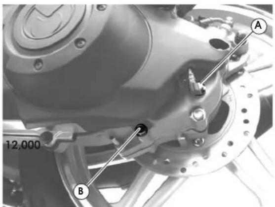
2) Unscrew the oil filling screw (A-Fig.24
3) If necessary, top up with the recommended type of oil (Q8 CLASS 10W40) until it overflows.
4) Refit and tighten the oil filling screw.
Renew after the first 1,000 km (624 mi) and every km (7,440 mi)
1) Place the vehicle on a level surface on its centre stand.
2) Put a container under the crankcase.
3) Loosen the drainage (B-Fig.24) and filling (A-Fig.24) screws.
4) Clean the drainage screw, refit and tighten in place.
5) Fill crankcase with the recommended type of oil (Q8 CLASS 10W40) until it overflows (150cc).
6) Refit and tighten the oil filling screw.

Perform this operation with the engine off and cold.

Prevent foreign matters from getting into transmission crankcase during checks or oil changes. Prevent oil dripping on tires or wheels.
text_image
12,000 A BFig.24

Regularly check for oil leakages near drain cap at the rear wheel. If you notice any leaks, contact an Authorised MALAGUTI Service Centre.

Hand waste oil over to an authorised waste diposal centre, in accordance to laws in force.

Malas
IDEE IN MOTO


5.4 ENGINE OIL
Check oil level every 2,000 km (1,248 mi)
As far as four-stroke engines are concerned, engine oil is used to lubricate distribution components, base bearings and the thermal unit. An insufficient amount oil can seriously damage the engine.
In all four-stroke engines, deterioration of the oil and a certain consumption are to be considered normal. Consumption, in particular, strictly relates to conditions of usage (oil consumption increases if the vehicle is used with the throttle fully open).
To prevent trouble, check the oil level more frequently with respect to the indications given in the MAINTENANCE TABLE, especially before long journeys.
Checking the oil level
This check should be performed when the engine is cold, as described below:
1) Park the vehicle on flat ground and put it stand.
2) Stop the engine and wait a few minutes for the oil to stabilise.
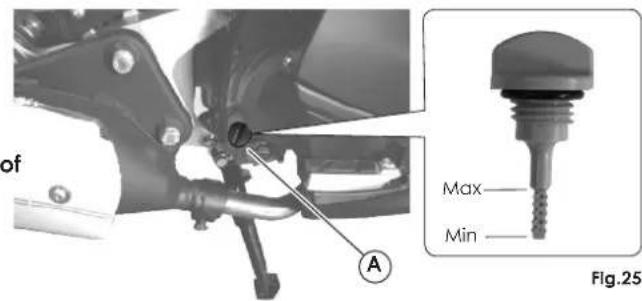
3) Unscrew the cap/dipstick (A-Fig.25), dry it with a clean cloth and retighten it.
4) Remove the cap/dipstick and make sure the level falls between the MAX and MIN notches; if necessary, top up with Q8 CLASS 10W40 oil.
Maximum amount of 1000cc.
Max. amount of oil for periodic renewing: 800cc.
5) Refit the cap/dipstick (A-Fig.25).
text_image
of A Max Min Fig.25
When checking the oil level, make sure the vehicle is upright; slight tilting may alter readings.

If you need to check the level when the engine is warm, I remember that the level line will be lower. It is best to wait at least 10 minutes from stopping the engine in order to have a correct reading


Topping up
Before topping up, check the oil level and in no case allow the level to rise above the MAX notch.

Never allow the level to rise above the MAX mark! Excessive internal pressure can impair performance and cause malfunctioning or damage to the engine.

Waste oil is toxic for the environment, therefore we suggest you contact an Authorised MALAGUTI Service Centre for disposal according to the rules in force.
Change engine oil and clean the filtering net after the first 1000 km (624 mi) and every 4000 km (2496 mi)
1) Warm the engine up for a few minutes.
2) Stop the engine. Put an oil container under the engine and remove the dipstick (A-Fig.26).
text_image
A F SFig.26 Fig.27
text_image
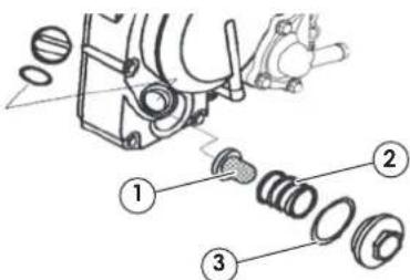
Technical diagram showing mechanical assembly with numbered parts for identification3) Remove drainage cap (S-Fig.26) and let oil flow out.
4) Remove filter cap (F-Fig.26
5) Clean the oil filtering net (1-Fig.27) with solvent.
6) Check the O-ring (3-Fig.27) and replace if damaged.
7) Refit O-ring, compression spring (2-Fig.27), oil filtering net and tighten filter cap.

Make sure the O-ring is correctly seated.
8) Refit drainage cap and wrench.
9) Fill the engine with 800cc. of Q8 CLASS 10W40 oil and refit the dipstick.
10) Run the engine and let it warm up; check for any leaks. If leaks are noted, stop the engine and locate their cause.
11) Repeat engine oil level check (see "Checking the oil level" chap.5.4).

Letting the engine run with an insufficient amount of lubricant or with the wrong types of lubricant causes wear to moving parts and can in the long run cause serious damage.

Waste oil contains polluting substances. Have oil replaced by an Authorised MALAGUTI Service Centre that will also dispose of waste oil in accordance to the law.

malagmi IDEE IN MOTO


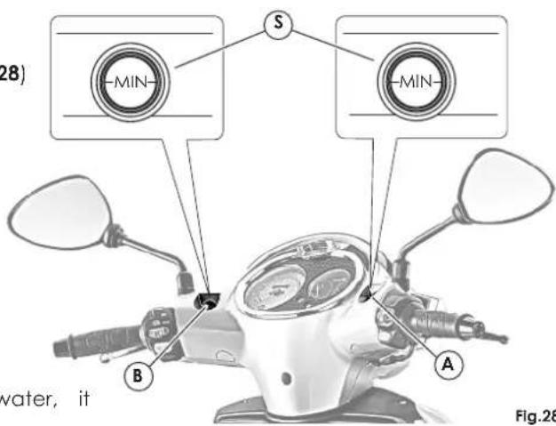
- The visual check should be made through the sight glass (S-Fig.28) of the tanks: front brake (A-Fig.28) and rear brake (B-Fig.28), when the vehicle is on level ground and perfectly upright.
- The oil should be at 3mm from the bottom edge of the sight glass.
- Topping up must be entrusted to an Authorised MALAGUTI Service Centre.

Hydraulic oil is corrosive and can cause damage and injuries. Do not mix different types of oil. Check the perfect seal of the gaskets.
Renew every 7,500 mi (12,000 km) or 24 months
- If the fluid features traces of dirt, debris or water, it must be replaced.
- A soft and spongy feeling in the brake lever can indicate the presence of air in the circuit. Immediately contact an Authorised MALAGUTI Service Centre.
text_image
28) MIN S MIN B A water, it Fig.28
To ensure long life and efficiency for your vehicle, we advise you to have these operations made by an Authorised MALAGUTI Service Centre.


malagmi IDEE IN MOTO

5.6 COOLANT
- The coolant expansion tank is located inside the front compartment and is protected by a plastic cover (chap.3.5).
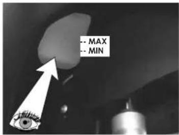
- The level of coolant can be checked using the "MIN" and "MAX" notches as reference. These are visible through the chassis number sight glass (Fig.29).
- Check the coolant level in the tank when the engine is cool, in order to avoid possible burnings.
- The coolant level is sufficient if it is included the "MIN" and "MAX" notches marked on the tank.
- If it is lower than the "MIN" notch, top up until you reach the "MAX" notch.
• We advise you to use: Q8 TOP FLUID - If you are using undiluted fluid, dilute with amount of water.
The cooling circuit is supplied with an electric fan, actuated by a thermistor, which automatically cools the fluid inside the radiator if its t reaches excessive levels. The electric fan is protected by a 7.5 A fuse located in the glove compartment (chap.3.6).
Before using the vehicle, check that the cooling surface of the radiator, located behind the front wheel, is not even partially clogged by leaves, paper, mud, etc.
Fluid temperature indicator
Temperature of coolant is displayed by the temperature indicator on the right hand side of the instrument board.
When coolant temperature rises above the permissible threshold, the indicator reaches the red zone of the scale and the relative warning light comes on (chap.3.11). In this case, stop the vehicle immediately. Allow the engine to cool down and check:
- that there are no objects clogging the cooling surface of the radiator located between the headlights (remove them);
- that there are no leaks inside the circuit with subsequent leak of fluid (see oil level, topping up);
- that the fan's fuse is in working order (if not, replace it).
the same

For any trouble inside the cooling circuit, we advise you to contact an Authorised MALAGUTI Service Centre for an extensive check as soon as possible, even if the cause of the trouble has already been removed.

temperature already been removed.
text_image
- MAX - MINFig.29

Malagami IDEE IN MOTO
5.7 LUBRICANT TABLE

Note: the vehicle's life depends also on the care devoted to lubricating it.
LUBRICANTS TYPE OF LUBRICANT
| ENGINE OIL (4-STROKE TYPE) | Q8 | CLASS 10W 40 |
| ENGINE TRANSMISSION OIL | Q8 | CLASS 10W 40 |
| AIR FILTER LUBRICANT | Q8 | AIR FILTER OIL |
| RADIATOR FLUID Q8 TOP FLUID | ||
| BRAKE CIRCUIT FLUID | Q8 | BRAKE FLUID DOT 4 |
| FORK ROD OIL Q8 FORK OIL |


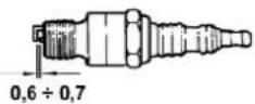
5.8 SPARK PLUG
Replace every 7,440 mi (12,000 km)
Recommended spark plugs: NGK DPR7EA9
The spark plug is an essential component:
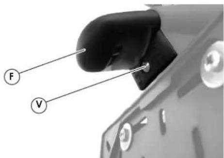
- Proper care of the plug is important for maintaining the engine in perfect working order.
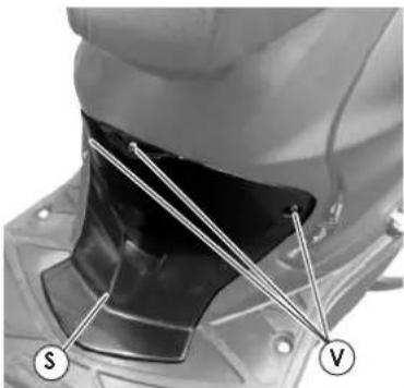
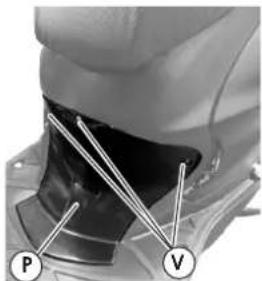
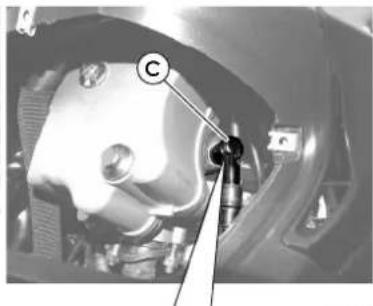
- For maintenance, remove the centre partition under the seat (P-Fig.30), by unscrewing the three fix screws (V-Fig.30) and raising the bottom profile (with the aid of a screwdriver) sealed onto the two teeth of the footboard. Carefully remove the cap by turning it clockwise and anticlockwise alternatively (C-Fig.31); Now, unscrew the spark plug using the special wrench supplied with the vehicle (all operations on the spark plug must be performed when the engine is cold).
- Examine the spark plug conditions after a reasonably long drive (10-15 km) and after letting the engine cool down (at least 10-15 minutes), since the sediments and the colour of the insulator can provide useful information about the heat rating of the spark plug, carburetion, lubrication and general conditions of the engine. A light brown colour of the insulator, around the central electrode, indicates good working order.
- After disassembling the spark plug, suitably clean the electrodes and the insulator using a metal brush. Adjust the electrode gap using a filler gauge: the gap should range from 0.6 ÷ 0.7 mm.
- Blow onto it so as to prevent possible residues from entering the engine, then refit it, by wrenching until finger tight. Then, using the special spark plug wrench, wrench it to the recommended torque wrench setting: 17.5 Nm / 1.75 kgm.

Spark plugs with a heat rating differing from the recommended one may seriously damage the engine.

It is imperative that any spark plug exhibiting cracks on the insulator or corroded electrodes be replaced.
natural_image
Close-up of a mechanical component with labeled parts P and V (no text or symbols beyond labels)Fig.30
natural_image
Close-up of a mechanical component with a labeled section (C) and a tool inserted, no visible text or symbols.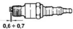
Fig.31
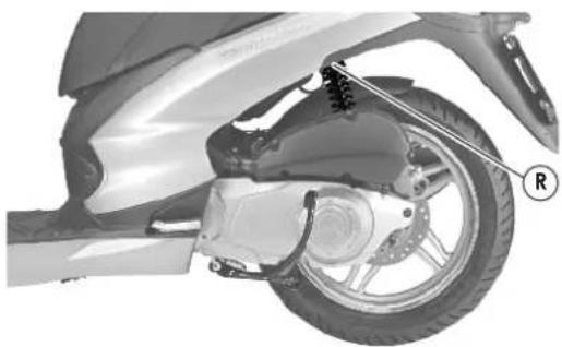
5.9 ADJUSTING REAR SHOCK ABSORBERS
- The shock absorbers are equipped with a spring preload ring nut, with which it is possible to adjust the vehicle's behaviour depending on the load carried, how the vehicle is driven and where.
- The adjustment is carried out using the wrench supplied, by acting on the ring nut located in the top section of the shock absorbers (R-Fig.32); turn anti clockwise to increase spring pre-load (load increase).
There are five adjustment positions:
1) light-weight driver only (up to 75 kg)
2) driver only
3) driver and luggage case
4) driver and passenger
5) driver, passenger and luggage case
natural_image
Mechanical assembly diagram of a scooter wheel and suspension system (no text or symbols)Fig.32

ATTENTION: adjust both shock absorbers according to the same adjustment index. An unbalanced adjustment may compromise the vehicle's stability.

While riding with a passenger, preload the shock absorber spring at position '4'.

When adjusting, wear gloves to protect yourself against scratching.
5.10 ADJUSTING ENGINE IDLING SPEED

For possible adjustments, please contact an Authorised MALAGUTI Service Centre.
5.11 THROTTLE FREE PLAY ADJUSTMENT
Check that the throttle grip idle stroke is 1-3 mm (measured on the end of the throttle grip).

Any adjustments must be entrusted to an Authorised MALAGUTI Service Centre.


Malagmi IDEE IN MOTO
Maintenance of the brake levers is limited to the brake fluid level check (chap.5.5).

A soft feeling in the brake levers could indicate the presence of air in the hydraulic circuit. In this event, refer to an Authorised MALAGUTI Service Centre for a check and circuit purging, if necessary.
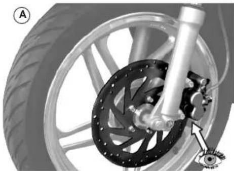
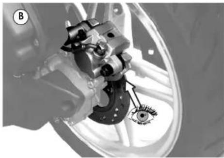
5.13 CHECKING PADS AND DISCS OF FRONT/REAR BRAKES
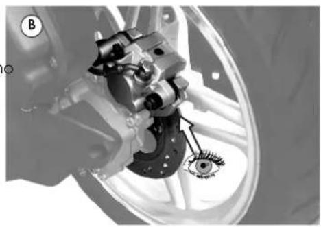
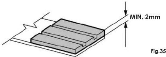
• We recommend that you check the front/rear pads and discs every 2,000 km (1,250 mi).
- Check the thickness of the brake pads as indicated by references A (front), B (rear) (Fig.33-34). The minimum thickness of the brake lining shall not be less than 2 mm (Fig.35).
- If the thickness of the pads is close to the lowest permitted limit or if they are damaged, have them replaced immediately.

It is absolutely necessary to replace the worn discs and pads as soon as possible. This operation must be performed by an Authorised MALAGUTI Service Centre using only original MALAGUTI spare parts.
natural_image
Mechanical assembly diagram showing a wheel, brake disc, and gear assembly (no text or symbols)Fig.33
natural_image
Mechanical assembly diagram showing a brake caliper and wheel assembly (no text or labels)Fig.34
text_image
MIN. 2mm Fig.35
Malagati IDEE IN MOTO


5.14 LIGHT
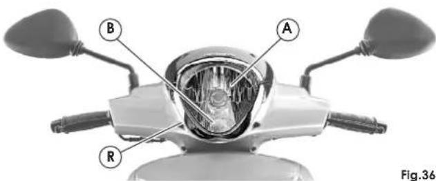
5.14.1 HEADLIGHT
To increase visibility at night, quartz (halogen) type headlights are fitted.
• Low beam / high beam (A-Fig.36)
Halogen bulb 12V - 60/55W (H4)
• Parking light bulb (B-Fig.36)
Bulb 12V - 5W (W5W)
For light controls, see chap.3.12.
- Using a Phillips screwdriver, turn the projector screw (R-Fig.36), bearing in mind that turning clockwise lowers the beam and vice versa.
- Adjust the beam so that its bottom line projected on the wall is at about 95cm from the floor.

Have the beam of the headlight periodically checked by an Authorised MALAGUTI Service Centre.

Note: We advise you to check if the replaced bulb works properly before refitting the headlight unit definitively.
ADJUSTING THE BEAM
To check/adjust the beam, proceed as follows:
- Put the vehicle in running conditions at 10 metres from a wall.
- Turn on the headlights and keep the vehicle balanced without a stand (lean it against a wall for instance).
text_image
A B R Fig.36


malagmi IDEE IN MOTO
REPLACING THE BULBS

Any replacements must be entrusted to an Authorised MALAGUTI SERVICE CENTRE.
5.14.2 FRONT TURN INDICATOR
• Front turn indicator (C-Fig.37)
Orange lamp 12V - 10W (RY10W)
REPLACING THE BULBS

The rate at which the turn indicator warning light on the instrument board flashes will increase to signal that one of the four indicators is not working.

Any replacements must be entrusted to an Authorised MALAGUTI SERVICE CENTRE.

natural_image
Front view of a scooter's head and front grille, labeled with 'C' and figure number 'Fig.37' (no text or symbols on the body)Fig.37

Malami
IDEE IN MOTO
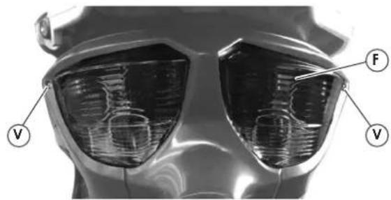
5.14.3 TAIL LAMP (WITH STOP LIGHT)
- Parking light (B-Fig.38)
Bulb 12V - 5W (W5W)
- Stop light (S-Fig.38)
Bulb 12V - 10W (R10W)
• Rear turn indicator (E-Fig.38)
Bulb 12V - 10W (R10W)

Note: visually check if the stop light works properly, by pulling one of the two brake levers.
text_image
V F V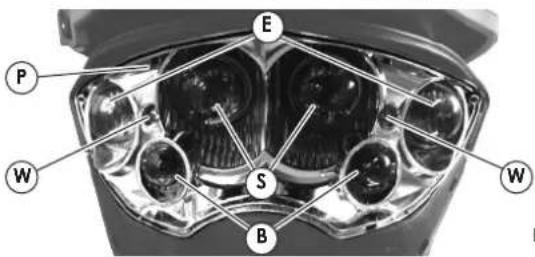
text_image
E P W S B WFig.38
REPLACING LAMPS
- Remove number plate light (see par.5.14.1).
- Remove cover of tail light (F-Fig.38) by loosening the 2 screws (V-Fig.38). Pay attention not to scratch the cover.
- Remove the parabola (P-Fig.38) by loosening the 2 screws (W-Fig.38).
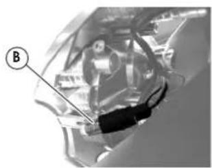
Parking light (B-Fig.39)
- Remove the lamp socket inside the lamp.
- Replace the light bulb.
- Refit the rubber lamp socket (by pressing) cover.
Stop light (S-Fig.40) and turn indicator (E-Fig.40)
- Remove the coloured cap, secured to the lamp by means of two hooks.
- Replace the light bulb.
- Refit the coloured cap and cover.

When performing the operations described above, pay attention not to damage parts nearby (transmission, wiring, gaskets, etc.)
natural_image
Interior view of a vehicle showing a mechanical component with labeled point B (no text or symbols beyond label)
text_image
S EFig.40Fig.39


Malagmi IDEE IN MOTO
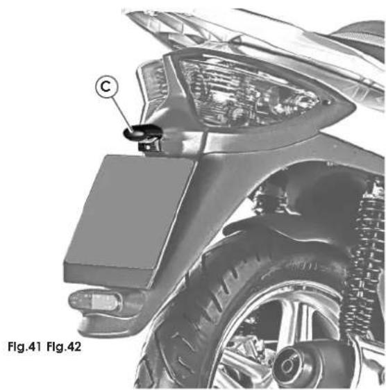
5.14.4 NUMBER PLATE LIGHT
• Number plate light (C-Fig.41) Bulb 12V - 5W (W5W)
To check if the number plate light (C-Fig.41) is working properly, flick the light switch, which is on the side control, to its central position and turn the key to starting position.
natural_image
Technical illustration of a car's front wheel assembly with labeled component (C), no readable text or symbols beyond labelsREPLACING THE BULBS
To replace the number plate light:
- Remove the number plate light cover (F-Fig.42), by loosening the screw (V-Fig.42).
- Remove the rubber lamp socket and plastic cover.
- Replace the light bulb.
highRedthe lamp socket and cove

When performing the operations described above, pay attention not to damage parts nearby (transmission, wiring, gaskets, etc.)
text_image
F V
Malacat
IDEE IN MOTO


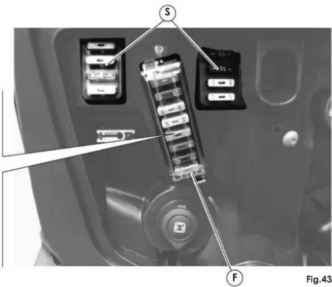
5.15 FUSES
The electrical equipment includes eight fuses protecting the main components against faults. These are located in the glove compartment (F-Fig.43). They are:
| A | Light 10s A | CK16C | |
| B | 7.5 A | STOP | Stop light + indicators |
| C | 5 A | ACC.MOTOR | Engine accessories activated when key is on |
| D | 5 A | ECU | Control unit |
| E | 30 A | PRINCIPAL | Main |
| F | 10 A | PUMP.I.E | Fuel pump |
| G | 7.5 A | Fan | |
| H | 30 A | CHARGE | Protection for battery recharging |
REPLACING THE FUSES
To replace a fuse, just open the lower fairing cover and, using the pliers supplied, extract the blown fuse and replace it with one of the same capacity. Inside the compartment, you will find some spare fuses Check that the fuse you are using has the same amperage of the fuse you are replacing.

Do not replace the fuse with one having a higher capacity, as it could seriously damage the electrical equipment and cause a fire on the vehicle in the event of a short circuit.
text_image
S F Fig.43(S

If the fuses blow, even if they have been replaced have them checked by an Authorised MALAGUTI Service Centre.


Malagmi IDEE IN MOTO
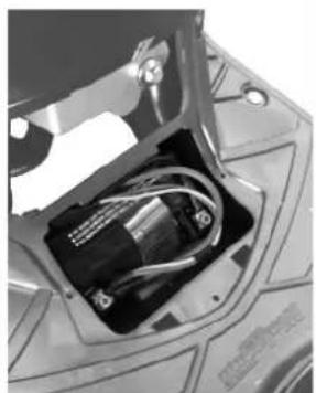
5.16 BATTERY (12V - 9Ah)
The battery housing is in the central channel.
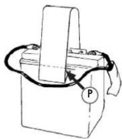
Fitting battery (operation performed before delivery)
To fit battery, proceed as follows:
- Take a charged battery.
- Apply the adhesive band supplied with the vehicle as shown in Fig.44, removing the two protective from the ends of the adhesive area, as shown by the arrow in the drawing (P-Fig.44).
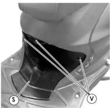
- Remove the 30A general protection fuse.
- Undo the 3 screws (V-Fig.45) and remove the centre partition under the seat (S-Fig.45).
- Remove the battery fixing cover by removing the two screws (C-Fig.46).
- Insert the battery and make sure it is correctly seated.
- Connect the battery wiring:
- positive pole (+) RED/BLUE cables
- negative pole (-) to the BLACK cables.
• Wrench down the battery terminals. - Refit the 30A general protection fuse previously removed.
- Check that the battery and the wiring harness are correctly installed; you can now refit the battery cover.
- Fit the partition.

NEVER invert the cable connections.

Do not use the vehicle if the battery has not been fitted correctly and connected to its cables. This may cause failures and short circuit of the electrical system and its components.

If the battery remains flat it will be seriously damaged.

We advise you to use protective gloves and goggles while removing the battery from its compartment, for example to recharge the battery.

Malas
IDEE IN MOTO


Battery recharging
- To carry out this operation, we advise you to remove the battery from its housing, unless the connection through the special plug (chap.3.6) is used.
- Disconnect the cables.
- It is good practice to recharge with amperage of 1/10 with respect to that of the charged battery.
- Refit the battery, being careful to connect positive cable (red/blue) to the + pole and the negative cable (black) to the - pole.
• Wrench down the battery terminals. - The battery must always be kept completely charged. During winter or when the vehicle is not used, charge the battery at least once a month.

Danger of explosion! Never use open flames (lighters, matches, etc.) to check the battery liquid level.

The battery contains sulphuric acid, which is highly toxic. Avoid any contact with eyes, skin or clothes.
the

If you are using the special socket (chap.3.6) to recharge/maintain the battery, it is recommended to open the battery compartment to provide sufficient ventilation.
natural_image
Simple line drawing of a battery with a switch and cable, no text or symbols presentFig.44 Fig.45 Fig.46 Fig.47
natural_image
Close-up of a mechanical component with labeled parts (S and V), no readable text or symbols present.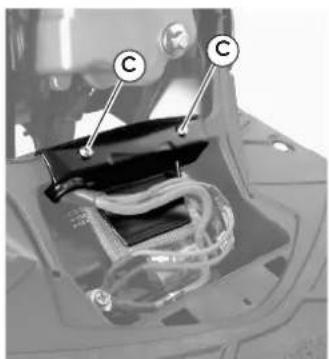
natural_image
Close-up of a mechanical component with labeled parts (C), showing internal structure without any readable text or symbols.
natural_image
Close-up of an electronic device showing internal components and wiring (no visible text or symbols)
Malagmi IDEE IN MOTO
5.17 TROUBLESHOOTING
If the vehicle does not operate correctly, run the checks and carry out the operations described herein.

If the problem persists, contact an Authorised MALAGUTI Service Centre, which has the required equipment and experience for any kind of adjustment and repair.
The vehicle does not brake or the brake lever travel is too long.
- For both hydraulic brakes, check the oil level in the brake pump chambers, located on the handlebar, and if necessary, have them topped up or purged by an Authorised MALAGUTI Service Centre.
- Check the thickness of the brakes pads every 1,250 mi (2,000 km).
THE ENGINE DOES NOT START
1) Brake lever not pulled:
- Operate one of the two brake levers.
2) Main switch not activated:
- Insert the key and turn it clockwise.
3) Flooded engine:
- Contact an Authorised MALAGUTI Service Centre.
4) Clogged or dirty air filter:
- Contact an Authorised MALAGUTI Service Centre.
5) The starter motor runs too slowly:
- The battery is flat or partially run down. Recharge tr battery.
- If the fault remains, contact an Authorised MALAGUTI Service Centre.
6) The starter motor works but the vehicle does not start:
- Check the state of the spark plug; if necessary clean or replace it.
- If the fault remains, contact an Authorised MALAGUTI Service Centre.
5.18 STORAGE
To keep the vehicle in good conditions before long term storage, remember to:
- Start and run the vehicle for about 10 minutes in order to drain any water and enable oil to spread over all internal mechanisms and walls.
- Remove the spark plug and pour a spoon of engine oil inside the head and then refit the spark
- Press the starter button a few times so as to allow the oil poured in to lubricate the parts subject to heat.
- Lubricate the control cables.
- Cover all metal surfaces with a coat of oil (not on rubber or plastic parts).
- emove the battery and recharge it.
• Store the vehicle in a dry place. - During long term storage, make sure there is enough fuel (approx. 1 litres) in the fuel tank to preserve the fuel pump in good working order. No fuel in the pump could cause serious damage.
5.19 CLEANING
To keep each part of your vehicle in perfect working order, we advise you to clean it properly.
- Before cleaning, protect the exhaust pipe and make sure that the spark plug and the fuel and oil tank caps are properly closed.
- For cleaning, never use chemical products, which plug may spoil the vehicle paintwork, plastic and rubber components, etc.
- Avoid using aggressive solvents, which can oxidise metal parts.
- An excessive water pressure while cleaning the vehicle may damage its mechanical and electrical components, especially those on the front side of the vehicle (handlebar, upper fairing, instrument board, lights, etc.).
- Avoid high pressure washing, for instance pressurised washing appliances and the like.
- While cleaning the vehicle, make sure that the cooling surface, situated in the front side, is not clogged by mud, paper, leaves, etc. In the presence of dirt, clean with a jet of water or air at a moderate pressure.


malagmi IDEE IN MOTO
Accessories
The vehicle can be fitted with following accessories: If you wish to fit electric or electronic accessories, always make sure that they do not interfere with the vehicle's normal operation and in case of doubt contact an Authorised MALAGUTI Service Centre for full information.
• LUGGAGE CASE OF A MATCHING COLOUR
• ELECTRONIC ANTI-THEFT DEVICE
- WINDSCREEN
• TARPAULIN
- If you wish to fit a non-approved part to the vehi contact MALAGUTI Spa before doing so, to find out if said accessory is compatible with your vehicle.

Note: the MALAGUTI spare parts catalogue is frequently updated. Contact your Authorised MALAGUTI Service Centre for information about the new accessories for your "CENTRO".
- MALAGUTI Spa grants the full compatibility of its vehicle with MALAGUTI original accessories. Always refer to an Authorised MALAGUTI Service Centre.
- MALAGUTI Spa is released from all liability for damage to the vehicle or to the user due to installation of non-original accessories. Likewise, MALAGUTI Spa is released from all liability for damage to the vehicle or harm to the user due to improper installation of accessories, original included, the said responsibility being borne by the party who performed said installation.

NOTES:
Malaguti recommends:
MALAGUTI ORIGINAL SPARE PARTS


Index
- INTRODUCTION ...... 2
1.1 SECTIONS DU MANUEL
1) INTRODUCTION

natural_image
Top-down line drawing of a car viewed from the side, showing internal components and structural lines (no text or symbols)Fig.1
Dimensions
empattement (A-Fig.1 P....
ORQJXHXU PD[ B-Fig.1 P....
ODUJHXU PD| C-Fig.1 P
KDXWHXU PD[D-Fig.1 P
SRLGV HQ RUGUH GH PDUFKH.N.I....140
FKDUJH PD[ FRQGXFWHXU SOXV SDVVDJHU HW EDJDJBONJ.....
Capacité
KXLOH PRWHXU Fó 1000*
KXILOH GH WUDQVPLVVLRQ Fó ..... LAHU UpVHUYRLU GH FDUEXUDQW GRQW UpVHUYH O .....
10 Lumière plaque 40
11 Porte-plaque
12 Anneau antivol 14
text_image
① ② ③ ⑧ ⑦ ⑥ ⑤ ④ Fig.2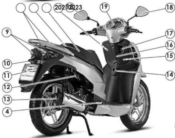
text_image
Labeled diagram of an electric scooter with numbered parts for identification and assembly reference.Fig.3
text_image
A Fig.4 B Fig.5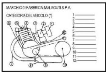
text_image
MARCHIO DI FABBRICA MALAGUTIS P.A. CATEGORIA DEL VEICOLO (*) 1 2 3 4 5 6 7 8 9 10 11 12
Malacat
IDEE IN MOTO
3.3 PNEUS
natural_image
Line drawing of a scooter with labeled X and Y components (no text or symbols on the diagram itself)| X | 100/80-16" 50P |
| Y | 120/80-16" 60P |

text_image
Diagram showing a car wheel switch mechanism and its labeled components A and B in the dashboard.Fig.8Fig.7

Malas
IDEE IN MOTO
3.5 RESERVOIR DU LIQUIDE DE REFROIDISSEMENT
natural_image
Close-up of a mechanical device with labeled component A, showing internal components and no readable text or symbols.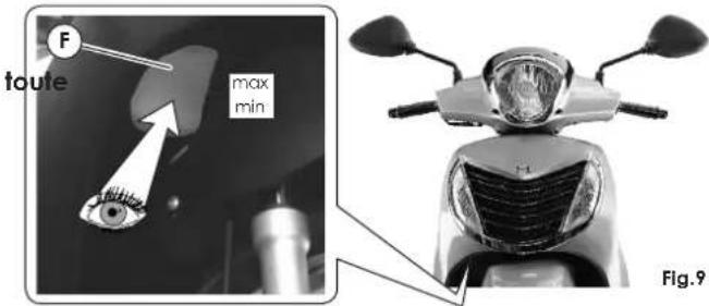
text_image
F toute max min Fig.93.6 COFFRE AVANT
natural_image
Close-up of a mirror with a labeled point P pointing to it, mounted on a stand (no text or symbols beyond the label)Fig.12
3.8 COFFRE A CASQUE
natural_image
Close-up of a white helmet partially inserted into a car's hood, with a close-up inset showing the gear detail (no visible text or symbols)


3.9 ACCROCHE-SAC
natural_image
Close-up of a mechanical component with a labeled section (G), showing internal structure and mounting holes (no text or symbols beyond label)Fig.15
3.10 ANNEAU ANTIVOL
natural_image
Close-up of a white motorcycle's wheel and suspension system, showing mechanical components and a labeled section (A), with no visible text or symbols.Fig.16

Malas
IDEE IN MOTO
3.11 TABLEAU DE BORD
natural_image
Front view of a silver electric scooter with visible motors and dashboard (no text or symbols)Fig.17
text_image
A B 3 2 1 Fig.18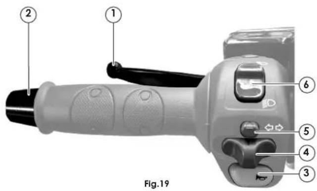
text_image
Fig.19text_image
NO. Fig.20 Fig.21
natural_image
Diagram of a mechanical component with a rotating shaft and curved arrow indicating rotation (no text or symbols)natural_image
Close-up of a mechanical component with a highlighted section and arrow pointing to it (no visible text or symbols)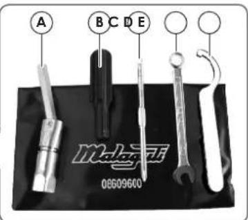
text_image
A B C D E Malzani 08609660Fig.22

Malas
IDEE IN MOTO
natural_image
Mechanical assembly diagram of a scooter showing wheel, brake, and mounting bracket (no text or symbols)

Malagmi IDEE IN MOTO
text_image
Technical diagram showing mechanical assembly with numbered parts for identificationFig.26 Fig.27
text_image
S MIN MIN A B Fig.28text_image
- MAX - MINFig.29

Malagmi IDEE IN MOTO
5.7 TABLEAU LUBRIFIANTS

natural_image
Mechanical assembly diagram showing a component labeled 'C' with a tool inserted, no readable text or symbols present.
5.9 RÉGLAGE AMORTISSEUR ARRIÈRE
natural_image
Close-up of a scooter's wheel and brake system with labeled component (R), no visible text or symbols beyond the label.Fig.32

natural_image
Mechanical assembly diagram showing a wheel, brake disc, and gear mechanism (no text or symbols)Fig.33

natural_image
Mechanical assembly diagram showing a brake caliper and wheel assembly with an eye symbol (no text or labels)Fig.34

text_image
MIN. 2mm Fig.355.14 FEU
5.14.1 FEU AVANT
Ampoule 12V - 5W (W5W)
REMPLACEMENT AMPOULES

REMPLACEMENT AMPOULES

natural_image
Front view of a scooter's head and front grille, labeled with 'C' and figure number 'Fig.37' (no text or symbols on the body)Fig.37

Malami
IDEE IN MOTO
Ampoule 12V - 5W (W5W)
• Feu de stop (S-Fig.38)
Ampoule 12V - 10W (R10W)
text_image
E P W S B WFig.38
REMPLACEMENT DES AMPOULES
natural_image
Close-up of a car interior showing engine compartment and dashboard (no visible text or symbols)
text_image
S EFig.40Fig.39


5.14.4 FEU PLAQUE
• Feu plaque (C-Fig.41)
Ampoule 12V - 5W (W5W)
REMPLACEMENT AMPOULES
natural_image
Technical illustration of a car's front wheel assembly with labeled component (C), no readable text or symbols beyond labels
text_image
S F Fig.43REPLACEMENT FUSIBLES
natural_image
Simple line drawing of a battery with a switch and a labeled component (no text or symbols)Fig.44 Fig.45 Fig.46 Fig.47

natural_image
Close-up of a mechanical component with labeled parts S and V, showing internal structure and mounting base (no readable text or symbols)
natural_image
Close-up of a mechanical component with labeled parts (C), showing internal structure and wiring (no readable text or symbols)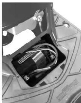
natural_image
Close-up of an electronic device showing internal components and wiring (no visible text or symbols)

Malagmi IDEE IN MOTO
5.17 DÉFAILLANCES DE FONCTIONNEMENT
natural_image
Top-down schematic of a vehicle viewed from the side, showing internal components and structural lines (no text or labels)Fig.1
Dimensiones
Paso (A-Fig.1) m.... 1,360
5 Caballete central 19
6 Batería 42
7 Gancho casco externo 13
8 Compartimento del casco 13
9 Luz trasera 39
text_image
① ② ③ ⑧ ⑦ ⑥ ⑤ ④ Fig.2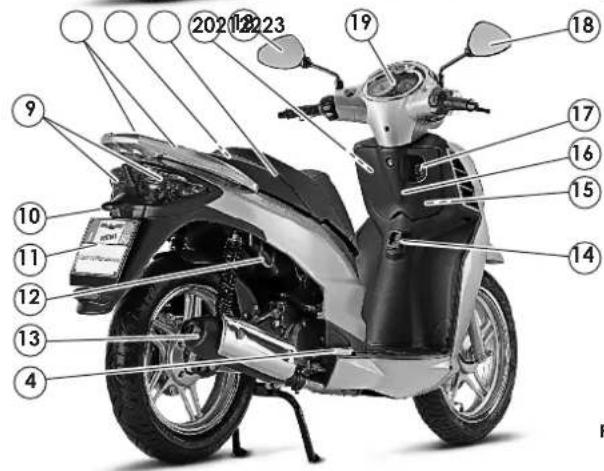
text_image
Labeled diagram of an electric scooter with numbered parts and a license plate visibleFig.3

Malagmi IDEE IN MOTO
text_image
A Fig.4 B Fig.5natural_image
Line drawing of a scooter with labeled X and Y axes (no text or symbols on the diagram itself)| X | 100/80-16" 50P |
| Y | 120/80-16" 60P |

natural_image
Diagram of a hand using a tool to lift a circular component, showing motion direction (no text or symbols)
text_image
A B
natural_image
Close-up of a mechanical device with labeled component A, showing internal components and no readable text or symbols.
natural_image
Close-up of a mirror with a labeled point P pointing to it, mounted on a desk lamp (no text or symbols beyond the label)Fig.12
3.8 COMPARTIMENTO DEL CASCO
natural_image
Technical illustration showing a mechanical component and a close-up of a car's wheel assembly (no text or symbols)


malagmi IDEE IN MOTO
3.9 GANCHO PORTAOBJETOS
natural_image
Close-up of a car front panel with a labeled component (G) pointing to a small electronic component (no text or symbols beyond the label)Fig.15
3.10 GANCHO ANTIRROBO
natural_image
Close-up of a white motorcycle's wheel and suspension system, showing mechanical components and mounting bracket (no text or symbols visible)Fig.16

Malas
IDEE IN MOTO
3.11 SALPICADERO
natural_image
Front view of a silver electric scooter's head and front wheel assembly (no visible text or symbols)Fig.17
text_image
A B 3 2 1 Fig.18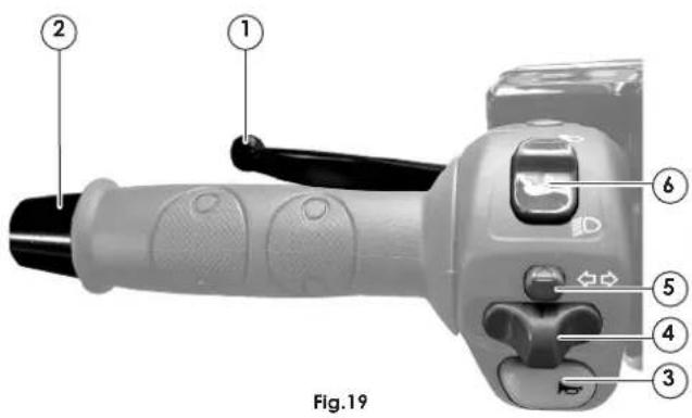
text_image
Fig.19
Malagmi IDEE IN MOTO
text_image
NO. Fig.20 Fig.21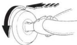
natural_image
Diagram of a mechanical component with a rotating shaft and curved arrow indicating rotation (no text or symbols)3.15 EQUIPAMIENTO ESTÁNDAR
natural_image
Close-up of a transparent mechanical component with a highlighted rectangular opening (no visible text or symbols)
text_image
A B C D E Malzani 08609600Fig.22

Malacat
IDEE IN MOTO
3.16 CABALLETE CENTRAL
text_image
Technical diagram showing mechanical assembly with numbered parts for identificationtext_image
mirilla MIN S MIN A B Fig.28text_image
- MAX - MINFig.29

Malagami IDEE IN MOTO
5.7 TABLA DE LUBRICANTES

natural_image
Close-up of a mechanical component with a labeled section (C) and a tool inserted, no visible text or symbols.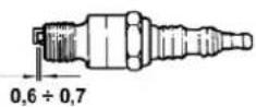
Fig.31
natural_image
Close-up of a scooter's wheel and suspension system, showing mechanical components and a labeled part (R) (no text or symbols beyond label)Fig.32
natural_image
Mechanical assembly diagram showing a wheel, brake disc, and eye component (no text or symbols)Fig.33
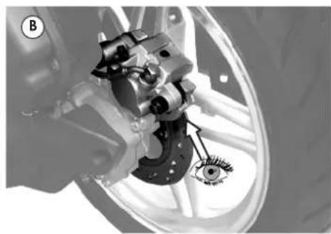
natural_image
Mechanical assembly diagram showing a brake caliper and wheel assembly (no text or labels)Fig.34

text_image
MIN. 2mm Fig.35
malagmi IDEE IN MOTO


5.14 LUCES
5.14.1 FARO DELANTERO
natural_image
Front view of a scooter's head and front grille, labeled with 'C' and figure number 'Fig.37' (no text or symbols on the body)Fig.37

Malami
IDEE IN MOTO
5.14.3 LUZ TRASERA (CON LUZ DE FRENO)
text_image
E P W S B WFig.38
CAMBIO DE BOMBILLAS
natural_image
Close-up of a car interior showing engine and dashboard components (no visible text or symbols)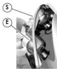
text_image
S EFig.40Fig.39


natural_image
Technical illustration of a car's front wheel assembly with labeled component (C), no readable text or symbols beyond labelsnatural_image
Simple line drawing of a battery with a switch and a labeled component (no text or symbols)Fig.44 Fig.45 Fig.46 Fig.47
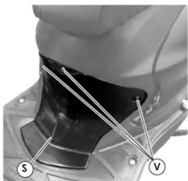
natural_image
Close-up of a mechanical component with labeled parts S and V, showing internal structure and mounting base (no readable text or symbols)
natural_image
Close-up of a mechanical component with labeled parts (C), showing internal structure and wiring (no readable text or symbols)
natural_image
Close-up of an electronic device interior showing internal components (no visible text or symbols)
Malagmi IDEE IN MOTO