
EG2850A - Generator MAKITA - Free user manual and instructions
Find the device manual for free EG2850A MAKITA in PDF.
| Brand | Makita |
| Model | EG2850A |
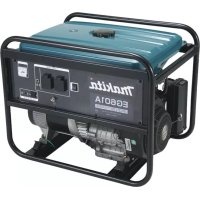
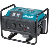
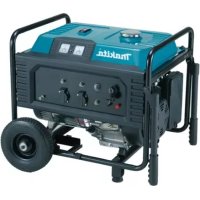
| Product type | Petrol generator, single-phase, brush, bipolar |
| Dimensions (L × W × H) | 600 × 442 × 450 mm |
| Weight (dry) | 45 kg |
| Gross weight (with wheels and handles) | 52,8 kg |
| Fuel | Unleaded petrol (octane rating ≥86, max E10) |
| Fuel tank capacity (full) | 15 L |
| Tank capacity (regulated volume) | 10 L |
| Engine oil capacity | 0,6 L |
| Engine oil type | 4-stroke, API SJ or later |
| Spark plug | Champion RN9YC, gap 0,7–0,8 mm |
| AC output – Voltage/Frequency | 230 V – 50 Hz |
| AC output – Rated current | 11,3 A |
| AC output – Rated power | 2600 W (VA) |
| AC output – Maximum power | 2800 W (VA) |
| DC output – Voltage | 12 V |
| DC output – Rated current | 8,3 A |
| Voltage regulation system | AVR (automatic voltage regulation) |
| Starting type | Recoil starter (electric starter optional with 12 V battery) |
| Safety devices | AC circuit breaker, DC circuit protector, oil alert system, emergency stop |
| Sound pressure level | 75 dB(A) (uncertainty K=3) |
| Sound power level | 95 dB(A) (uncertainty K=3) |
| Supplied accessories | Wheel and handle kit (for models ≥EG4550A, not supplied for EG2850A) |
| Routine maintenance | Check oil before each use; clean air filter every 3 months or 50 h; change oil every 6 months or 100 h; check spark plug every 6 months |
| Warranty | Consult the manual or an authorized Makita dealer |
Frequently Asked Questions - EG2850A MAKITA
User questions about EG2850A MAKITA
0 question about this device. Answer the ones you know or ask your own.
Ask a new question about this device
Download the instructions for your Generator in PDF format for free! Find your manual EG2850A - MAKITA and take your electronic device back in hand. On this page are published all the documents necessary for the use of your device. EG2850A by MAKITA.
USER MANUAL EG2850A MAKITA
GB Petrol Generator Instructions for Use
natural_image
Line drawing of a portable gas generator with visible circuit board and wheels, accompanied by warning symbols (no text or labels)
1
2

3
4
5
6
7
8
9
10
11 12
m = 311
13 14
-
15 16
[Non-Text]
17 18

19 20
21 22
natural_image
Technical line drawing of a mechanical device with visible gears and shafts (no text or symbols)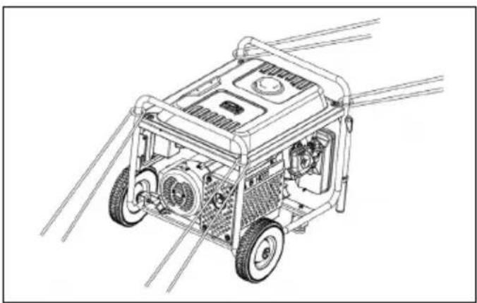
natural_image
Line drawing of a portable gas generator with visible motors and wiring (no text or symbols)23 24
natural_image
Line drawing of a portable gas generator with wheels and control panel (no text or symbols)25 26
natural_image
Technical line drawing of a vehicle's rear suspension system with mounting hardware (no text or symbols)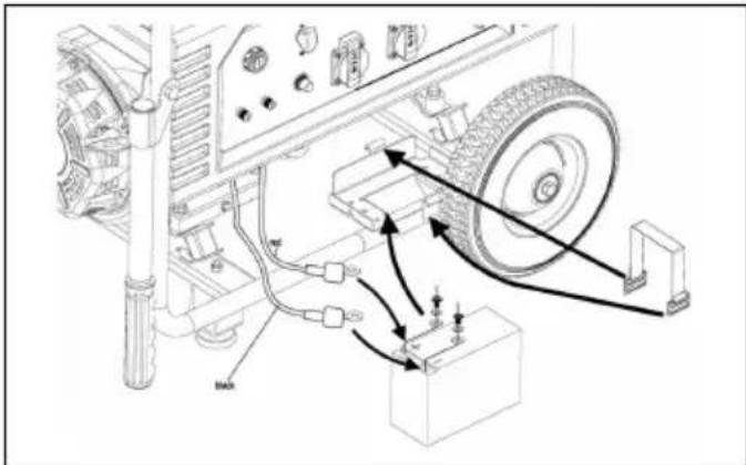
27
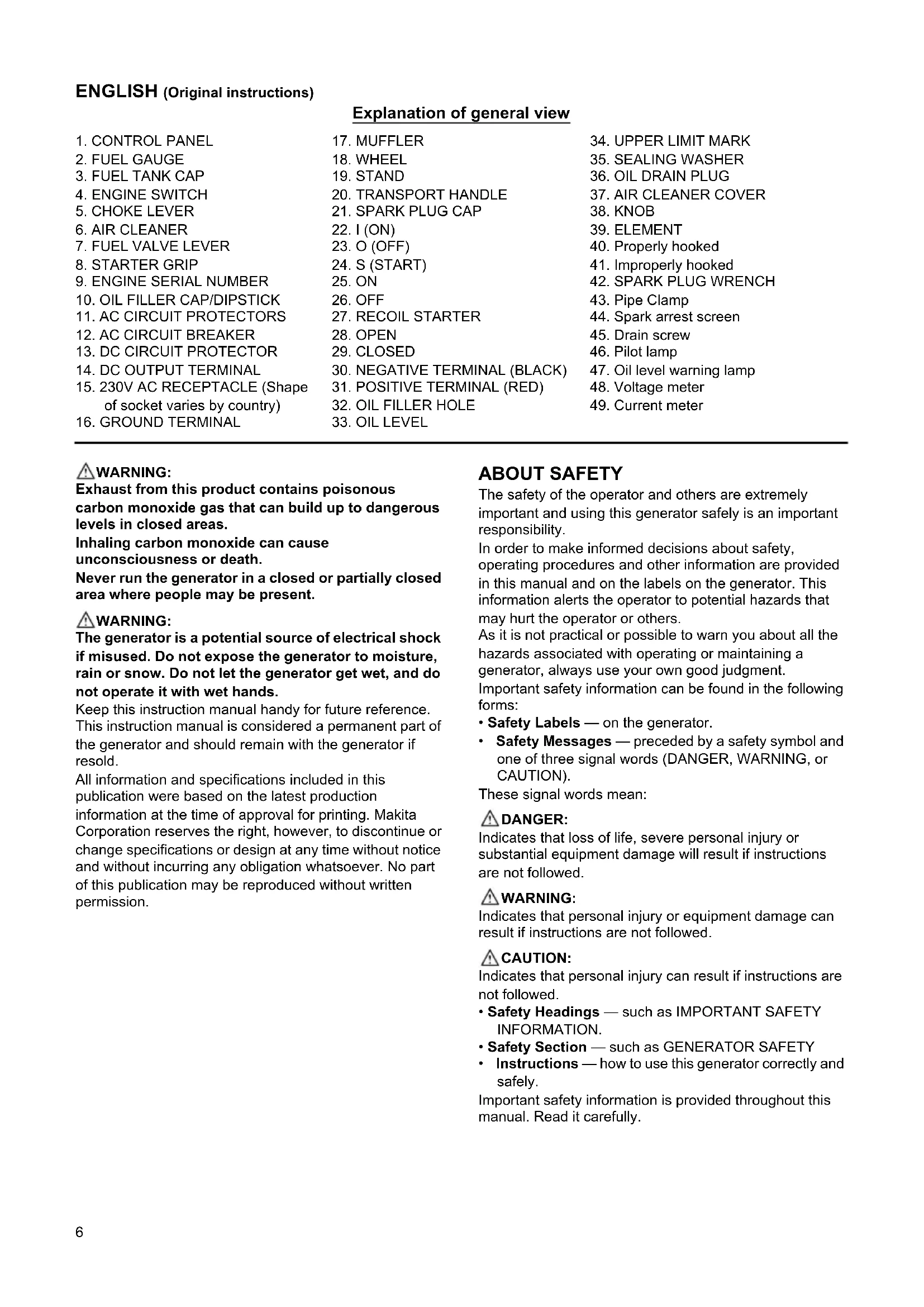
ENGLISH (Original instructions)
| Explanation of general view | ||
| 1. CONTROL PANEL | 17. MUFFLER | 34. UPPER LIMIT MARK |
| 2. FUEL GAUGE | 18. WHEEL | 35. SEALING WASHER |
| 3. FUEL TANK CAP | 19. STAND | 36. OIL DRAIN PLUG |
| 4. ENGINE SWITCH | 20. TRANSPORT HANDLE | 37. AIR CLEANER COVER |
| 5. CHOKE LEVER | 21. SPARK PLUG CAP | 38. KNOB |
| 6. AIR CLEANER | 22. I (ON) | 39. ELEMENT |
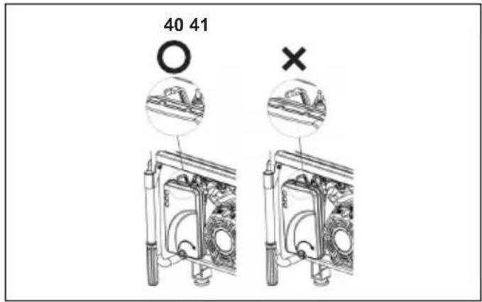
| 7. FUEL VALVE LEVER | 23. O (OFF) | 40. Properly hooked |
| 8. STARTER GRIP | 24. S (START) | 41. Improperly hooked |
| 9. ENGINE SERIAL NUMBER | 25. ON | 42. SPARK PLUG WRENCH |
| 10. OIL FILLER CAP/DIPSTICK | 26. OFF | 43. Pipe Clamp |
| 11. AC CIRCUIT PROTECTORS | 27. RECOIL STARTER | 44. Spark arrest screen |
| 12. AC CIRCUIT BREAKER | 28. OPEN | 45. Drain screw |
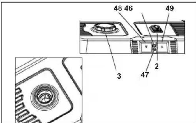
| 13. DC CIRCUIT PROTECTOR | 29. CLOSED | 46. Pilot lamp |
| 14. DC OUTPUT TERMINAL | 30. NEGATIVE TERMINAL (BLACK) | 47. Oil level warning lamp |
| 15. 230V AC RECEPTACLE (Shape of socket varies by country) | 31. POSITIVE TERMINAL (RED) | 48. Voltage meter |
| 32. OIL FILLER HOLE | 49. Current meter | |
| 16. GROUND TERMINAL | 33. OIL LEVEL | |
WARNING:
Exhaust from this product contains poisonous carbon monoxide gas that can build up to dangerous levels in closed areas.
Inhaling carbon monoxide can cause unconsciousness or death.
Never run the generator in a closed or partially closed area where people may be present.
WARNING:
The generator is a potential source of electrical shock if misused. Do not expose the generator to moisture, rain or snow. Do not let the generator get wet, and do not operate it with wet hands.
Keep this instruction manual handy for future reference. This instruction manual is considered a permanent part of the generator and should remain with the generator if resold.
All information and specifications included in this publication were based on the latest production information at the time of approval for printing. Makita Corporation reserves the right, however, to discontinue or change specifications or design at any time without notice and without incurring any obligation whatsoever. No part of this publication may be reproduced without written permission.
ABOUT SAFETY
The safety of the operator and others are extremely important and using this generator safely is an important responsibility.
In order to make informed decisions about safety, operating procedures and other information are provided in this manual and on the labels on the generator. This information alerts the operator to potential hazards that may hurt the operator or others.
As it is not practical or possible to warn you about all the hazards associated with operating or maintaining a generator, always use your own good judgment. Important safety information can be found in the following forms:
- Safety Labels — on the generator.
- Safety Messages — preceded by a safety symbol and one of three signal words (DANGER, WARNING, or CAUTION).
These signal words mean:
DANGER:
Indicates that loss of life, severe personal injury or substantial equipment damage will result if instructions are not followed.
WARNING:
Indicates that personal injury or equipment damage can result if instructions are not followed.
CAUTION:
Indicates that personal injury can result if instructions are not followed.
- Safety Headings — such as IMPORTANT SAFETY INFORMATION.
- Safety Section — such as GENERATOR SAFETY
- Instructions — how to use this generator correctly and safely.
Important safety information is provided throughout this manual. Read it carefully.
GENERATOR SAFETY
SYMBOLS and MEANINGS
In accordance with the European requirements (eec Directives), the specified symbols as shown in the following table are used for the products and this instruction manual.
 | Read the operator's instruction manual. |  | Fire, open light and smoking prohibited. |
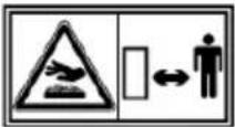 | Stay clear of the hot surface. |  | Do not connect the generator to the commercial power lines. |
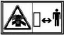 | Exhaust gas is poisonous.Do not operate in an unventilated room. |  | Gasoline |
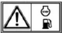 | Stop the engine before refueling. |  | Call for maintenance. |
 | Caution, risk of electric shock. |  | Keep dry. |
IMPORTANT SAFETY INFORMATION
Makita generators are designed to give safe and dependable service if operated according to instructions.
Read and understand this instruction manual before operating the generator. To prevent accidents, be familiar with the generator's controls and observe safe operating procedures.
Responsibilities of the Operator
- The operator must know how to quickly stop the generator in case of an emergency.
- The operator must have knowledge of the use of all generator controls, output receptacles, and connections.
- The operator must make sure that anyone who operates the generator receives proper instruction. Do not let children operate the generator without parental supervision.
Carbon Monoxide Hazards
- Exhaust from this generator poisonous carbon monoxide, a colorless and odorless gas. Inhaling carbon monoxide can cause loss of consciousness and may lead to death.
- If the generator is operated in a closed or partially closed area, the air may contain a dangerous amount of exhaust gas.
- Never run the generator inside a garage, house, or near open windows or doors.
Electric Shock Hazards
- The generator produces enough electric power to cause a serious electrical shock or electrocution if misused.
- Do not use the generator or an electrical appliance in wet conditions, such as rain or snow, or near a pool or sprinkler system, or with wet hands. Such action may result in electrocution. Keep the generator dry.
- If the generator is stored outdoors and is unprotected from the weather, check all of the electrical components on the control panel before each use. Moisture or ice can cause a malfunction or short circuit in the electrical components which may result in electrocution.
- Do not connect the generator to a building's electrical system unless an isolation switch has been installed by a qualified electrician.
Fire and Burn Hazards
- The exhaust system can become hot enough to ignite flammable materials.
- Keep the generator at least 3 feet (1 meter) away from structures or buildings and other equipment during use.
- Do not enclose the generator in any structure.
- Keep flammable materials away from the generator.
- The muffler becomes very hot during operation and remains hot for a while after the engine is stopped. Be careful not to touch the muffler while it is hot. When storing the generator indoors, allow the engine cool before it is stored.
- Gasoline is extremely flammable and is explosive under certain conditions. Do not smoke while refueling the generator or near where gasoline is stored. Keep flames/sparks away from where the generator is refueled or where gasoline is stored. Refuel in a well-ventilated area with the engine stopped.
- Fuel vapors are extremely flammable and may ignite after the engine is started. If fuel is spilled, wipe it up and let dry before starting the generator.
Other Safety Information:
- Personal protective equipment is required for any operation and maintenance.
- The load must be kept within the rating stated on generator rating plate. Overloading the generator will damage the unit or shorten its life.
- The generator must not be run at excessive speeds. Operation at excessive speeds will increase the hazards of personal injury.
- Do not modify parts which may increase or decrease the governed speed.
- Only use extension cords that are grounded and are a sufficient wire gauge for the application. When using an extended wire or a mobile electric net, if the wire diameter is 1.5 ~mm^2 , it cannot exceed the length of 60 m. If the wire diameter is 2.5 ~mm^2 , it cannot exceed the length of 100 m.
- The exhaust system can become hot enough to ignite flammable materials. Do not operate the engine near flammable materials. Do not use the generator in damp conditions.
- Do not store fuel indoors or try to refuel a generator while it is running.
- Do not cover unit while it is being used.
- To prevent poisoning or fire when operating, never use the generator in close proximity to flammable materials.
- The unit must reach the operating speed before the electrical loads are connected. Disconnect the load before turning off the generator. Turn off all of the equipment powered by the generator before shutting down the generator. The unit should not be connected to other power supply outlets.
- Protection against electrical shock is dependent on the circuit breakers specially matched to the generating set. If the circuit breaker requires replacement contact a local retailer for replacement with a circuit breaker having identical rating and performance characteristics.
- Ensure that the generator does not have any damaged hoses, loose or missing clamps, damaged tank or cap before use. All defects should be corrected before use.
- The installation and major repair of the generator can only be conducted by specially trained people. Before transporting the generator, drain all fuel to prevent leakage.
- Store the generator in a well-ventilated area with the fuel tank empty.
COMPONENTS (Fig. 1)
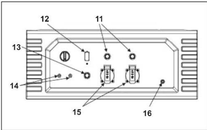
CONTROL PANEL (Fig. 2 & Fig. 3)
*Keep a record of the engine and frame serial numbers and the date of purchase for your future reference. Refer to these serial numbers when ordering parts and when making technical or warranty inquiries.
Date of purchase:
Engine serial number:
Frame serial number:
CONTROLS
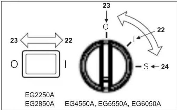
Engine Switch (Fig. 4)
Starts and stops the engine.
Key position:
O (OFF): Stops the engine. Key can be removed or inserted.
I (ON): Runs the engine after starting.
S (START): Starts the engine by operating the starter motor.
*EG2250A and EG2850A equipped with I (ON)/O (OFF) switch only
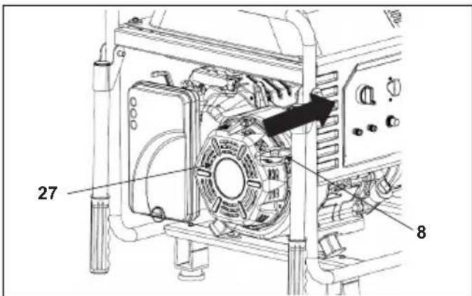
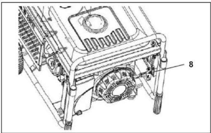
Starter Grip (Fig. 5)
To start the engine, pull the starter grip slowly until resistance is felt and then pull swiftly.
NOTICE:
Return the starter grip back gently to prevent damage to the starter. Do not allow it to snap back against the engine.
If the generator is not equipped with a 12-volt battery to operate the starter motor or if the battery does not contain enough charge to operate the starter motor, the recoil starter is used to start the engine.
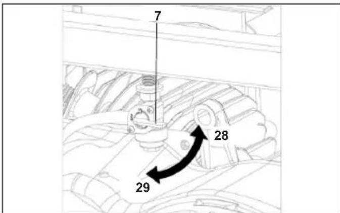
Fuel Valve Lever (Fig. 6)
The fuel valve is located between the fuel tank and carburetor. Fuel is allowed to flow from the fuel tank to the carburetor when the valve lever is in the "I (ON)" position. Return the fuel valve lever to the "O (OFF)" position after stopping the engine.
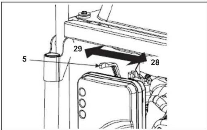
Choke Rod (Fig. 7)
The choke is used to provide an enriched fuel mixture when starting a cold engine. Operate the choke rod manually to open and close the choke. Pull the rod out toward "CLOSED" to enrich the mixture for cold starting.
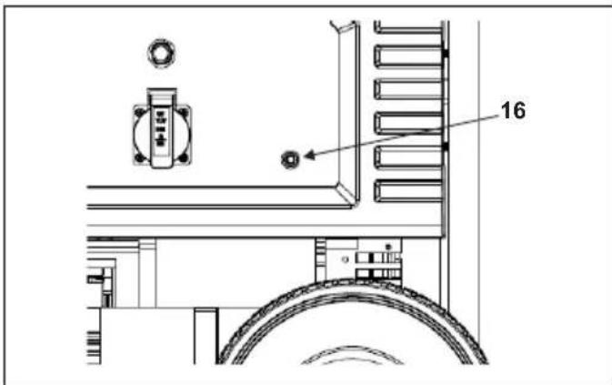
Ground Terminal (Fig. 8)
The generator ground terminal is connected to the generator frame, the generator's metal non-current-carrying parts, and each receptacle's the ground terminals.
Before using the ground terminal, consult a qualified electrician, an electrical inspector, or a local agency having jurisdiction for local codes or ordinances that apply to the intended use of the generator.
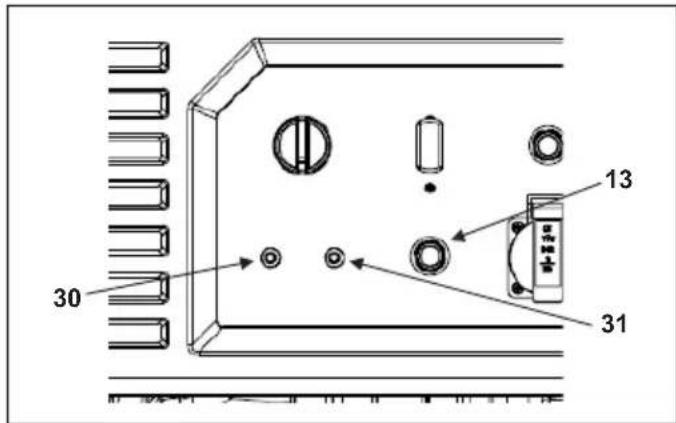
DC Terminals
The DC terminals are used only for charging 12-volt automotive type batteries.
The terminals are colored red and black to identify the positive (+) and negative (-) terminals, respectively. Make sure to connect the battery to the generator DC terminals with the correct polarity (battery positive to the generator red terminal and battery negative to the generator black terminal).
DC Circuit Protector (Fig. 9)
When the DC charging circuit is overloaded, there is a problem with the battery, or the connections between the battery and the generator are incorrect, the DC circuit protector automatically shuts off the DC battery charging circuit.
Oil Alert System (Fig. 14)
The engine can be damaged if there is an insufficient amount of oil in the crankcase. The Oil Alert system prevents this from happening by automatically stopping the engine before the oil level in the crankcase falls below the safe limit (the engine switch will remain in the "I (ON)" position). When the oil alert system works, the oil level warning lamp lights up in red. The oil level should always be checked before each use, regardless of this Oil Alert system.
If the engine stops and fails to restart, check the engine oil level before troubleshooting in other areas.
NOTICE:
When the amount of oil in the crankcase is sufficient, the pilot lamp lights up in green. When the amount of oil is insufficient, the oil level warning lamp lights up in red. Be sure to add oil before using the generator.
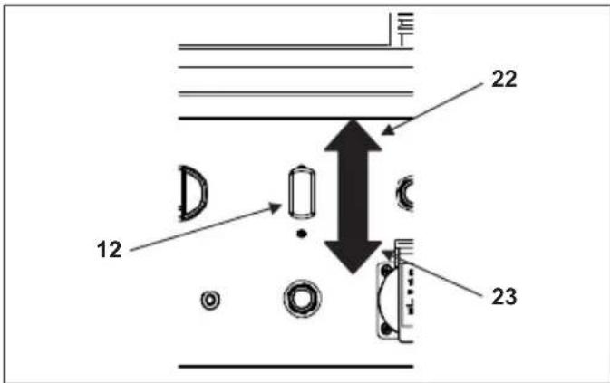
AC Circuit Breaker (Fig. 10)
The AC circuit breaker automatically turns off if there is a short circuit or a significant overload of the generator at the receptacle. If the AC circuit breaker is turns off automatically, make sure that the appliance is working correctly and does not exceed the rated load capacity of the circuit before turning on the AC circuit breaker again. The AC circuit breaker may be used to turn the generator power on or off.
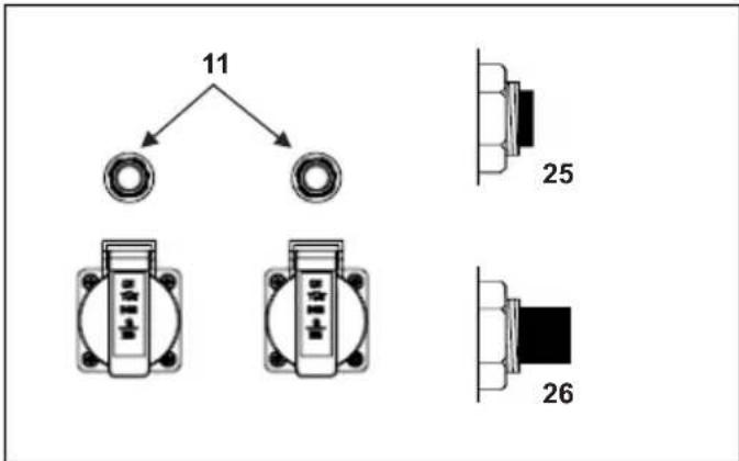
AC Circuit Protector (EG4550A, EG5550A, EG6050A only) (Fig. 11)
The AC circuit protectors automatically turn off if there is a short circuit or a significant overload of the generator at the 26A 230V. If an AC circuit protector turns off automatically, make sure that the appliance is working correctly and does not exceed the rated load capacity of the circuit before resetting the AC circuit protector on.
GENERATOR USE
Connections to a Building's Electrical System
A qualified electrician must make the connections for standby power to a building's electrical system. Make sure that the connection isolates the generator power from the utility power, and complies with all applicable laws and electrical codes. A transfer switch, which isolates generator power from utility power, can be purchased through authorized Makita generator dealers.
WARNING:
Electrical current from the generator may backfeed into the utility lines if connections to a building's electrical system are made improperly. Such backfeed may electrocute utility company workers or others who come into contact with the lines during a power outage, and the generator may explode, burn, or cause fires when the utility power is restored. Consult the utility company or a qualified electrician.
Ground System
Makita portable generators are equipped with a system ground that connects generator frame components to the ground terminals in the AC output receptacles. Since the system ground is not connected to the AC neutral wire, if the generator is tested by a receptacle tester, it will show the same ground circuit condition as for a home receptacle.
AC Applications
Before connecting an appliance or power cord to the generator:
- Make sure that it is in good working condition. Faulty appliances or power cords can cause electrical shock.
- If an appliance begins to operate in an abnormal manner, becomes slow, or stops suddenly, turn it off immediately. Disconnect the appliance, and determine whether there is a problem with the appliance or if the rated load capacity of the generator has been exceeded.
- Make sure that the electrical rating of the tool or appliance does not exceed the generator's rating. Never exceed the maximum power rating of the generator. Power levels between rated and maximum may be used for no more than one hour.
NOTICE:
Substantial overloading will turn off the circuit breaker.
Exceeding the time limit for maximum power operation or slightly overloading the generator may not turn off the circuit breaker or circuit protector, but will shorten the service life of the generator.
Limit operation requiring maximum power to one hour.
Maximum power is as follows:
EG2250A: 2.2 kW
EG2850A: 2.8 kW
EG4550A: 4.5 kW
EG5550A: 5.5 kW
EG6050A: 6.0 kW
For continuous operation, do not exceed the rated power.
Rated power is as follows:
EG2250A: 2.0 kW
EG2850A: 2.6 kW
EG4550A: 4.0 kW
EG5550A: 5.0 kW
EG6050A: 5.5 kW
The total power requirements (VA) of all appliances connected to the generator must be considered. Rating information for appliances and power tools are usually listed near the model number or serial number.
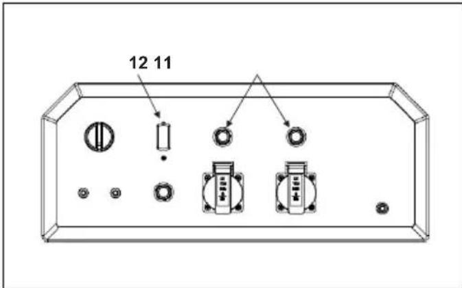
AC Operation (Fig. 12)
- Start the engine.
- Turn on the AC circuit breaker.
- Plug in the appliance.
NOTICE:
Before connecting any appliance to the generator, make sure they are in good working condition. If an appliance begins to operate in an abnormal manner, becomes slow, or stops suddenly, turn off the ignition switch lever immediately. Then disconnect the appliance and check for signs of malfunction.
Most motorized appliances require more than their rated power for startup.
Do not exceed the current limit specified for any one receptacle. If an overloaded circuit causes the AC circuit breaker or AC circuit protector to turn off, reduce the
electrical load on the circuit, wait a few minutes and then reset the AC circuit breaker or AC circuit protector.
DC Operation
The DC terminals are used only for charging 12-volt automotive type batteries.
Connecting the battery charging cables:
- Before connecting the battery charging cables to a battery that is installed in a vehicle, disconnect the vehicle ground battery cable from the negative (-) terminal of the battery.

WARNING:
The battery gives off explosive gases. Keep sparks, flames, and cigarettes away. Provide adequate ventilation when charging or using batteries.
WARNING: Lead and lead components are used in battery posts, terminals, and related accessories. Always wash hands after handling.
- Connect the positive (+) battery cable to the positive (+) terminal of the battery.
- Connect the other end of the positive (+) battery cable to the positive (+) terminal of the generator.
- Connect the negative (-) battery cable to the negative (-) terminal of the battery.
- Connect the other end of the negative (-) battery cable to the negative (-) terminal of the generator.
- Start the generator.
NOTICE:
Do not start the vehicle while the battery charging cable is connected and the generator is running. Doing so may damage the vehicle or the generator.
The DC circuit protector will be tripped (the "PUSH" button will extend out), if the DC circuit is overloaded, excessive current is drawn by the battery, or a wiring problem occurs. If this happens, wait a few minutes before pushing in the circuit protector to resume operation. If the DC circuit protector continues to go off, discontinue charging and consult your authorized Makita generator dealer.
Disconnecting the battery cables:
- Stop the engine.
- Disconnect the negative (-) battery cable from the negative (-) terminal of the generator.
- Disconnect the other end of the negative (-) battery cable from the negative (-) terminal of the battery.
- Disconnect the positive (+) battery cable from the positive (+) terminal of the generator.
- Disconnect the other end of the positive (+) battery cable from the positive (+) terminal of the battery.
- Reconnect the vehicle ground battery cable to the negative (-) terminal of the battery.
High Altitude Operation
At high altitudes, the standard carburetor air-fuel mixture will be too rich, and will cause performance to decrease and fuel consumption to increase. A very rich mixture will also foul the spark plug and cause hard starting.
Operation for extended periods of time at an altitude that differs from the altitude at which this engine was certified may increase emissions.
Engine horsepower decreases about 3.5% for every 1,000-foot (300-meter) increase in altitude, even with carburetor modification. If no carburetor modification is
made in the carburetor, the effect of altitude on horsepower will be even greater. High altitude performance can be improved by making specific modifications to the carburetor. If the generator is to always be operated at altitudes above 5,000 feet (1,500 meters), have your dealer perform this carburetor modification. This engine, when operated at high altitudes with the carburetor modifications for high altitude use, will meet the various emission standards throughout its useful life.
NOTICE:
When the carburetor has been modified for high altitude operation, the air-fuel mixture will be too lean for use at low altitudes. Operation at altitudes below 5,000 feet (1,500 meters) with a modified carburetor may cause the engine to overheat and result in serious engine damage. For low altitude use, have your servicing dealer return the carburetor to the original factory specifications.
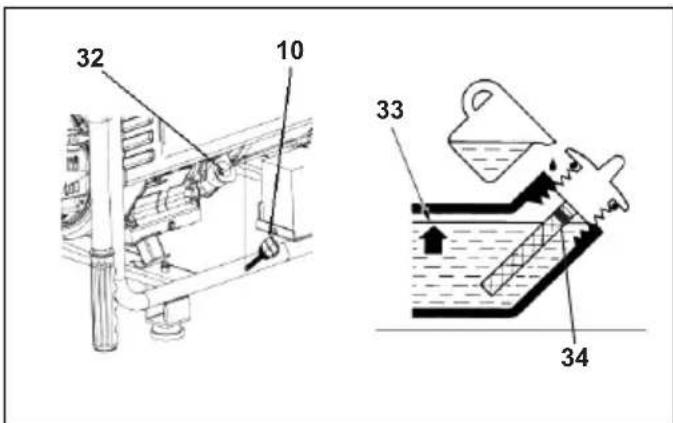
Check the oil level before each use with the engine stopped and the generator on a stable and level surface. Use 4-stroke motor oil that meets or exceeds the requirements for API Service Category SJ or later (or equivalent). Always check the API SERVICE label on the oil container to be sure the letters SJ or later (or equivalent) are indicated.
- Remove the oil filler cap/dipstick and wipe the dipstick clean.
- Insert the dipstick into the filler neck and check the oil level. Do not screw in the filler cap.
- If the oil level is low, fill to the upper limit of the oil filler neck with the recommended oil.
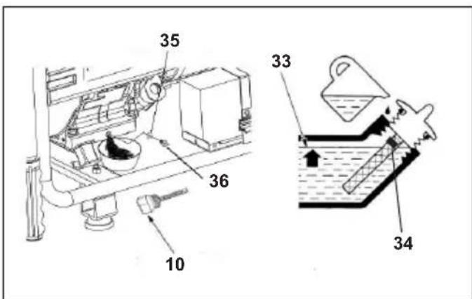
Check Engine Fuel (Fig. 14)
With the engine stopped, check the fuel level gauge. Refill the fuel tank if the fuel level is low.
WARNING:
Gasoline is highly flammable and explosive.
Burns or severe personal injury may result from handling fuel.
- Stop the engine and keep heat, sparks, and flames away.
• Refuel only outdoors. - Wipe up spills immediately.
Refuel in a well-ventilated area with the engine stopped. Allow the engine to cool first if it has been running. Refuel carefully to avoid spilling fuel. Do not fill above the upper limit mark.
Never refuel the engine inside a building where gasoline fumes may reach flames or sparks. Keep gasoline away from appliance pilot lights, barbecues, electric appliances, power tools, etc.
Spilled fuel is a fire hazard and causes environmental damage. Be sure to wipe up spills immediately.
NOTICE:
Be careful not to spill fuel when filling the fuel tank as fuel can damage paint and plastic. Damage caused by spilled fuel is not covered by the warranty.
After refueling, reinstall the fuel tank cap firmly.
Recommended Fuels
This engine is certified to operate on regular unleaded gasoline with a pump octane rating of 86 or higher.
Never use stale or contaminated gasoline or an oil-gasoline mixture. Avoid getting dirt or water in the fuel tank.
Regular unleaded gasoline containing no more than 10% ethanol (E10) or 5% methanol by volume can be used. In addition, the methanol must contain cosolvents and corrosion inhibitors.
If fuels containing levels of ethanol or methanol greater than those shown above are used, starting and/or performance problems may occur. The metal, rubber, and plastic parts of the fuel system may also be damaged.
Engine damage or performance problems resulting from the use of fuel with percentages of ethanol or methanol greater than the values shown above are not covered by the warranty.
STARTING/STOPPING THE ENGINE
Starting the Engine
For safety reasons, do not operate the generator in an enclosed area such as a garage. The generator's exhaust contains poisonous carbon monoxide gas that can collect rapidly in an enclosed area and cause illness or death.
WARNING:
Exhaust from the generator contains poisonous carbon monoxide gas that can build up to dangerous levels in closed areas.
Inhaling carbon monoxide can cause unconsciousness or death.
Never run the generator in a closed or partially closed area where people may be present.
To prevent fires, keep the generator at least 3 feet (1 meter) away from buildings and other structures during operation. Keep flammable objects away from the engine.
NOTICE:
Do not operate this generator less than 3 feet (1 meter) from a building or other obstruction. Doing so can cause overheating and/or damage the generator. In order to maintain proper cooling, allow at least 3 feet (1 meter) of empty space above and around the generator.
Refer to the "AC OPERATION" or "DC OPERATION" of this manual for how to connect loads to the generator.
-
Perform the PRE-OPERATION CHECKS.
-
Make sure that the AC circuit breaker is in the "O (OFF)" position. It may be difficult to start the generator if a load is connected.
-
Turn the fuel valve lever to the "I (ON)" position.
-
Turn the engine switch to the "I (ON)" position.
-
Pull the starter grip slowly until resistance is felt, then pull swiftly.
NOTICE:
Return the starter grip back gently to prevent damage to the starter. Do not let it snap back against the engine.
With the electric starter:
-
Connect the battery cables to the generator.
-
Turn the engine switch to the "S (START)" position and hold it there for 5 seconds or until the engine starts.
NOTICE:
- The motor can be damaged if the starter motor is operated for more than 5 seconds. If the engine fails to start, release the switch and wait 10 seconds before operating the starter again.
- If the speed of the starter motor drops after a period of time, it is an indication that the battery should be recharged.
When the engine starts, allow the engine switch to return to the "I (ON)" position.
If the choke was manually closed, push it to the "OPEN" position as the engine warms up.
Stopping the Engine
In an emergency:
To stop the engine in an emergency, move the engine switch to the "O (OFF)" position.
In normal use:
-
Turn the AC circuit breaker to the "O (OFF)" position. Disconnect the DC battery charging cables.
-
Turn the engine switch to the "O (OFF)" position.
-
Turn the fuel valve lever to the "O (OFF)" position.
MAINTENANCE
The Importance of Maintenance
Good maintenance is vital to the safe, economical, and trouble free operation of the generator. It will also help reduce air pollution.
WARNING:
Improper maintenance, or failure to correct a problem before operation, can cause a malfunction which can result in severe personal injury or loss of life.
Always follow the inspection and maintenance recommendations and schedules in this instruction manual.
The following pages include a maintenance schedule, routine inspection procedures, and simple maintenance procedures using basic hand tools required for properly caring for the generator. Other service tasks that are more complicated or require special tools are best handled by professionals and are normally performed by a Makita technician or other qualified mechanic.
The maintenance schedule included in this manual is based on normal operating conditions. If the generator is operated under severe conditions, such as sustained high-load or high-temperature operation, or it is used in unusually wet or dusty conditions, consult your servicing dealer for recommendations applicable to your specific needs and use.
Maintenance, replacement, or repair of the emission control devices and systems may be performed by any nonroad engine repair establishment or individual, using parts that are “certified” to EPA standards.
Maintenance Safety
The following are some of the most important safety precautions. However, we cannot cover every conceivable hazard that can arise in performing maintenance, so please remember that only you can decide whether or not you should perform a given task.

WARNING:
Failure to properly follow maintenance instructions and precautions can cause severe personal injury or loss of life.
Always follow the procedures and precautions in the instruction manual.
Safety Precautions
- Make sure the engine is off before beginning any maintenance or repairs. This will eliminate several potential hazards:
- Carbon monoxide poisoning from engine exhaust.
Operate outside away from open windows or doors.
- Burns from hot parts.
Let the engine and exhaust system cool before touching.
- Injury from moving parts.
Do not run the engine unless instructed to do so.
- Read the instructions before you operate the generator, and make sure you understand the instructions and have the tools and skills required.
- To reduce the possibility of fire or explosion, be careful when working around gasoline. Use only a non-flammable solvent, not gasoline, to clean parts. Keep cigarettes, sparks, and flames away from all fuel-related parts.
Remember that your servicing dealer knows your generator best and is fully equipped to maintain and repair it.
To ensure the best quality and reliability, use only new, genuine Makita parts or their equivalents for repair or replacement.
Maintenance Schedule
| REGULAR SERVICE PERIOD *3 | Each use | First month or 20 hrs. | Every 3 months or 50 hrs. | Every 6 months or 100 hrs. | Every year or 300 hrs. | |
| MAINTENANCE ITEMSPerform at every indicated month or operating hour interval, whichever comes first. | ||||||
| Engine oil Check level | ○ | |||||
| Change | ○ | ○ | ||||
| Air Cleaner Check | ○ | |||||
| Clean | ○*1 | |||||
| Sediment cup Clean | ○ | |||||
| Spark plug Check-adjust | ○ | |||||
| Replace | ○ | |||||
| Spark arrester Clean | ○ | ○*2 | ||||
| Idle speed Check-adjust | ||||||
| Valve clearance Check-adjust | ○*2 | |||||
| Combustion clean chamber | After every 500 hrs. *2 | |||||
| Fuel tank and clean filter | ○*2 | |||||
| Fuel tube Check Every 2 years (Replace if necessary) | *2 | |||||
*1: Service more frequently when using the generator in dusty, dirty or severe environments.
*2: Unless the owner has the proper tools and is mechanically proficient, this item should be serviced by an authorized Makita generator dealer. Refer to the Makita Shop Manual.
*3: For commercial use, hours of operation should be logged to determine proper maintenance intervals.
Failure to follow this maintenance schedule may result in non-warrantable malfunctions.
Engine Oil Change (Fig. 15)
Drain the oil while the engine is warm to assure quick and complete draining.
- Place a suitable container below the engine to catch the oil.
- Drain the oil by removing the oil drain plug, the sealing washer, and the oil filler cap/dipstick.
- Reinstall the oil drain plug and a new sealing washer and firmly tighten the plug.
- Refill with the recommended oil and check the oil level.
Wash your hands with soap and water after handling used oil.
NOTICE:
Improper disposal of used engine oil can be hazardous to the environment. Before changing the oil, check for a suitable way to dispose of the used oil. Do not discard it in a trash bin, pour it down a drain, or dump it on the ground. Your local zoning or environmental regulations will give you more detailed instructions on proper disposal.
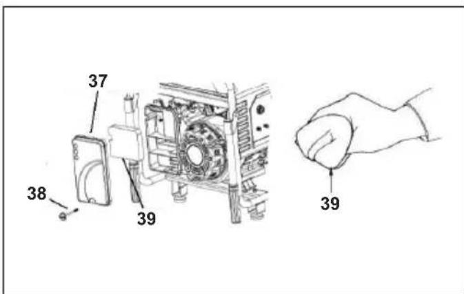
Air Cleaner Service (Fig. 16 & Fig. 17)
A dirty air cleaner will restrict air flow to the carburetor. To prevent carburetor malfunction, clean the air cleaner regularly. Clean more frequently when operating the generator in extremely dusty areas.
NOTICE:
Operating the engine without an air filter, with a damaged air filter, or with an improperly installed air filter will allow dirt to enter the engine, causing rapid engine wear. This type of damage is not covered by the Distributor's Limited Warranty.
- Remove the knob, unhook the two air cleaner cover clips, and then remove the air cleaner cover and the element.
- Wash the air cleaner element with a solution of household detergent and warm water, then rinse thoroughly, or wash with a nonflammable or high flashpoint solvent. Then, allow the air cleaner element to dry thoroughly.
- Soak the air cleaner element in clean engine oil and squeeze out the excess oil. If too much oil is left in the air cleaner element, the engine will smoke during initial startup.
- Reinstall the air cleaner element and the cover.
Fuel Sediment Cup Cleaning
The sediment cup prevents any dirt or water that may be in the fuel tank from entering the carburetor. Be sure to clean the sediment cup if the engine has not been run for a long period of time.
- Turn the fuel valve lever to the "O (OFF)" position. Remove the sediment cup, O-ring, and filter.
- Clean the sediment cup and filter with a nonflammable or high flash point solvent.
- Reinstall the filter, new O-ring, and sediment cup.
- Turn the fuel valve lever to the "I (ON)" position and check for leaks.
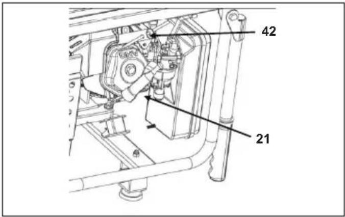
Spark Plug Service (Fig. 18 & Fig. 19)
A spark plug wrench (commercially available) is required to service the spark plug.
Recommended spark plugs: RN9YC (Champion), BPR5ES (NGK), W16EPR-U (DENSO) In order for the engine to operate properly, the spark plug must be properly gapped and free of deposits.
NOTICE:
Using an incorrect spark plug can damage the engine. Let the engine cool before servicing the spark plug, if the engine has been running.
- Remove the spark plug cap.
- Clean any dirt from around the spark plug base.
-
Use a spark plug wrench to remove the spark plug.
-
Visually inspect the spark plug. Discard it if the insulator is cracked, chipped, or fouled.
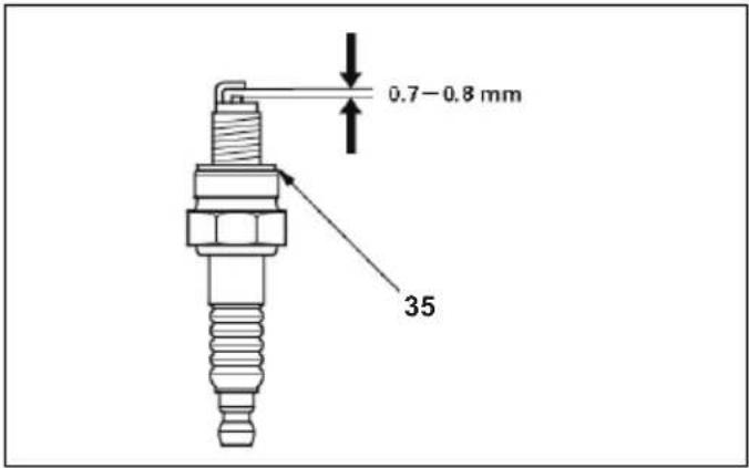
-
Measure the spark plug electrode gap with a wire-type feeler gauge. If necessary, correct the gap by carefully bending the side electrode. The gap should be: 0.7 - 0.8 mm
-
Check that the spark plug sealing washer is in good condition, and then thread the spark plug in by hand to prevent cross-threading.
-
After the spark plug is seated, tighten with a spark plug wrench to compress the washer.
- If installing a new spark plug, tighten 1/2 turn after the spark plug seats to compress the washer. If reinstalling a used spark plug, tighten 1/8 to 1/4 turns after the spark plug seats to compress the washer.
NOTICE:
If the spark plug is loose, it can overheat and damage the engine.
If the spark plug is over tightened, it can damage the threads in the cylinder head.
Spark Arrester Maintenance (country specific) (Fig. 20)
If the generator has been running, the muffler will be very hot. Allow it to cool before cleaning the spark arrester. In order to keep the spark arrester functioning as designed, it must be serviced every 100 hours.
Clean the spark arrester as follows:
- Loosen the screw by the exhaust port of the muffler and remove the spark arrester.
- Use a brush to remove carbon deposits from the spark arrester screen.
The spark arrester must be free of breaks or tears. Inspect it and replace it if damaged. - Install the spark arrester in the reverse order of removal.
STORAGE
Storage Preparation
Proper storage preparation is vital to keep the generator trouble-free and looking good. The following steps will help to keep rust and corrosion from impairing the generator's performance and appearance, and will make the engine easier to start when you use the generator again.
Cleaning
Wipe down the generator with a moist cloth and let it dry completely. Touch up any damaged paint and coat other areas that may rust with a light film of oil.
Fuel
NOTICE:
Fuel formulations may deteriorate and oxidize rapidly, depending on the region where the equipment is operated. Fuel deterioration and oxidation can occur in as little as 30 days and may cause damage to the carburetor and/or fuel system. Check with your servicing dealer for local storage recommendations.
Gasoline will oxidize and deteriorate in storage. Old gasoline will cause hard starting, and it leaves gum deposits that clog the fuel system. If the gasoline in the generator deteriorates during storage, the carburetor and other fuel system components may need to be serviced or replaced.
The length of time that gasoline can be left in the fuel tank and carburetor without causing functional problems will vary with factors such as gasoline blend, your storage temperatures, and whether the fuel tank is partially or completely filled. The air in a partially filled fuel tank promotes fuel deterioration. Very warm storage temperatures accelerate fuel deterioration. Fuel deterioration problems may occur within a few months, or even less if the gasoline was not fresh when you filled the fuel tank.
Fuel system damage or engine performance problems resulting from neglected storage preparation is not covered by the Distributor's Limited Warranty.
Fuel storage life can be extended by adding a gasoline stabilizer that is formulated for that purpose. Or, drain the
carburetor, sediment cup (if applicable) and/or fuel tank to avoid fuel deterioration problems.
Service according to the table below:
| LENGTH OF STORAGE RECOMMENDED SERVICE PROCEDURES TO PREVENT HARD STARTING | |
| Less than 1 month No preparation required. | |
| 1 to 2 months Fill with fresh gasoline and add gasoline stabilizer*. | |
| 2 months to 1 year | Fill with fresh gasoline and add gasoline stabilizer*.Drain the carburetor float bowl and the fuel sediment cup. |
| 1 year or more | Fill with fresh gasoline and add gasoline stabilizer*.Drain the carburetor float bowl and the fuel sediment cup.Remove the spark plug and put a teaspoon of engine oil into the cylinder. Turn the engine slowly with the recoil starter to distribute the oil. Then, reinstall the spark plug.Change the engine oil.After removing the generator from storage, drain the stored gasoline into a suitable container, and fill with fresh gasoline before starting. |
| *Use gasoline stabilizers that are formulated to extend storage life.Follow the manufacturer's instructions for use.Contact our authorized Makita generator dealer for stabilizer recommendations. | |
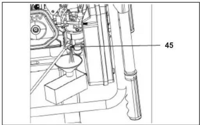
Draining the Fuel Tank and Carburetor (Fig. 21)
WARNING:
Gasoline is highly flammable and explosive.
Burns or severe personal injury may result from handling fuel.
- Stop the engine and keep heat, sparks, and flames away.
- Handle fuel only outdoors.
- Wipe up spills immediately.
- Loosen the drain screw and drain the carburetor. Drain the gasoline into a suitable container.
- Place a suitable gasoline container below the sediment cup, and use a funnel to avoid spilling gasoline.
- Remove the sediment cup, and then turn the fuel valve lever to the "I (ON)" position.
- Allow the gasoline to drain completely, and then reinstall the sediment cup.
Engine Oil (Fig. 22)
- Change the engine oil.
- Remove the spark plug.
- Pour a teaspoon (5 - 10 cc) of clean engine oil into the cylinder.
- Pull the starter grip several times to distribute the oil in the cylinder.
- Reinstall the spark plug.
- Pull the starter grip slowly until resistance is felt. The piston is coming up on its compression stroke at this point, and both the intake and exhaust valves are closed. Storing the engine in this position will help to protect it from internal corrosion. Return the starter grip back gently to its original position.
Storage Precautions
If the generator is to be stored with gasoline in the fuel tank and carburetor, it is important to reduce the hazard of gasoline vapor ignition.
Select a well ventilated storage area away from furnaces, water heaters, or clothes dryer, or any other appliance that operates with a flame. Also avoid areas with a spark-producing electric motor, or where power tools are operated.
Since high humidity promotes rust and corrosion, avoid storage areas with high humidity when possible.
Unless all of the fuel has been drained from the fuel tank, leave the fuel valve in the "O (OFF)" position to reduce the possibility of leakage.
Place the generator on a stable and level surface. Tilting can cause the fuel or oil to leak.
Once the engine and exhaust system are cool, cover the generator to keep out dust. A hot engine and exhaust system can ignite or melt certain materials.
Do not use sheet plastic as a dust cover. A nonporous cover will trap moisture around the generator, promoting rust and corrosion.
Removal from Storage
Check the generator as described in the "PRE-OPERATION CHECKS" chapter of this manual. Fill the fuel tank with fresh gasoline if the fuel was drained during storage preparation. If gasoline for refueling is kept in a container, be sure that it contains only fresh gasoline. Gasoline oxidizes and deteriorates over time, and using oxidized and/or deteriorated oil will cause hard starting. Note that if the cylinder was coated with oil during storage preparation, it is normal for the engine to smoke briefly at startup.
TRANSPORTING (Fig. 23)
When transporting the generator, turn off the engine switch and the fuel valve. Keep the generator stable and level to prevent fuel from spilling. Fuel vapor or spilled fuel may ignite.

WARNING:
Contact with a hot engine or exhaust system can result in serious burns or fire. Allow the engine cool before transporting or storing the generator.
When transporting the generator, take care not to drop or strike the generator. Do not place heavy objects on the generator.
When transporting the generator on a vehicle, secure to the generator frame as shown.
TROUBLESHOOTING
When the engine fails to start:
| Check if fuel is in the tank. | ←→ | If empty, refill the fuel tank. |
| Check the fuel level. | ←→ | If low, add the recommended oil. |
| Check the condition of the spark plug. | ←→ | If in bad condition, readjust the gap and dry the spark plug. Replace if necessary. |
| Check if fuel is reaching the carburetor. | ←→ | If not, clean the fuel sediment cup. |
If the engine still fails to start, take the generator to an authorized Makita generator dealer.
When no electricity is generated at the AC receptacles:
| Check that the AC circuit breaker is in the “I (ON)” position. | ←→ | If not, turn on the AC circuit breaker. |
| Check if the electrical appliance or equipment has any defects. | ←→ | If there are no defects, take the generator to an authorized Makita generator dealer.If there are defects:- Replace the electrical appliance or equipment.- Take the electrical appliance or equipment to an electrical shop to be repaired. |
TECHNICAL INFORMATION
Emission Control System Information
Source of Emissions
Carbon monoxide, oxides of nitrogen, and hydrocarbons are produced in the combustion process. Controlling the emission of hydrocarbons and oxides of nitrogen is extremely important because, under certain conditions, they react to form photochemical smog when subjected to sunlight. Although carbon monoxide does not react in the same way, it is toxic.
Makita utilizes the appropriate air-fuel ratios and other emissions control systems in order to reduce the emissions of carbon monoxide, oxides of nitrogen, and hydrocarbons.
Furthermore, Makita fuel systems utilize components and control technologies in order to reduce evaporative emissions.
Tampering and Altering
The level of emissions may increase beyond the legal limit, if the emission control system is tampered with or altered. Acts that constitute tampering include:
- Removal or alteration of any part of the intake, fuel, or exhaust systems.
- Altering or defeating the governor linkage or speed-adjusting mechanism to cause the engine to operate outside its design parameters.
Problems That May Affect Emissions
If you become aware of any of the following symptoms, have the engine inspected and repaired by your servicing dealer.
- Hard starting or stalling after starting.
- Rough idle.
- Misfiring or backfiring under load.
• Afterburning (backfiring). - Black exhaust smoke or high fuel consumption.
Replacement Parts
The emission control systems on your Makita engine were designed, built, and certified to conform to applicable emission regulations. Therefore, it is recommended that genuine Makita parts be used whenever you have maintenance done. Since these original-design replacement parts are manufactured to the same standards as the original parts, their performance is reliable. Using replacement parts that are not of the original design and quality may decrease the effectiveness of the emission control system. Note that manufacturers producing aftermarket parts assume the responsibility that the part will not adversely affect emission performance. The manufacturer or rebuilder of the part must certify that the engine will still comply with emission regulations even with the use of the part.
Maintenance
Follow the Maintenance Schedule. Remember that this schedule is based on the assumption that the machine will be used for the purpose it is designed. The machine will require more frequent service for continuous high-load or high-temperature operation, or use in unusually wet or dusty conditions.
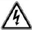
WIRING DIAGRAM
flowchart
graph TD
    A["Electric Generator"] --> B["Stud"]
    B --> C["Main Coil"]
    B --> D["Drive Coil"]
    B --> E["Rotor Coil"]
    B --> F["Direct-current Winding"]
    G["Panel"] --> H["Class 1 Mutual Inductor"]
    G --> I["Class 2 Mutual Inductor"]
    G --> J["9.6/12.5A Overcurrent Protective Device"]
    K["Engine"] --> L["Engine Oil Level Switch"]
    K --> M["Spark Plug"]
    K --> N["Ignition Coil"]
    O["77A"] --> P["Overcurrent Protective Device"]
    Q["7A"] --> R["Overcurrent Protective Device"]
    S["7B"] --> T["Overcurrent Protective Device"]
    U["7C"] --> V["Overcurrent Protective Device"]
    W["7D"] --> X["Overcurrent Protective Device"]
    Y["7E"] --> Z["Overcurrent Protective Device"]
    AA["7F"] --> AB["Overcurrent Protective Device"]
    AC["7G"] --> AD["Overcurrent Protective Device"]
    AE["7H"] --> AF["Overcurrent Protective Device"]
Note: Wiring is the same for the EG2250A and EG2850A.
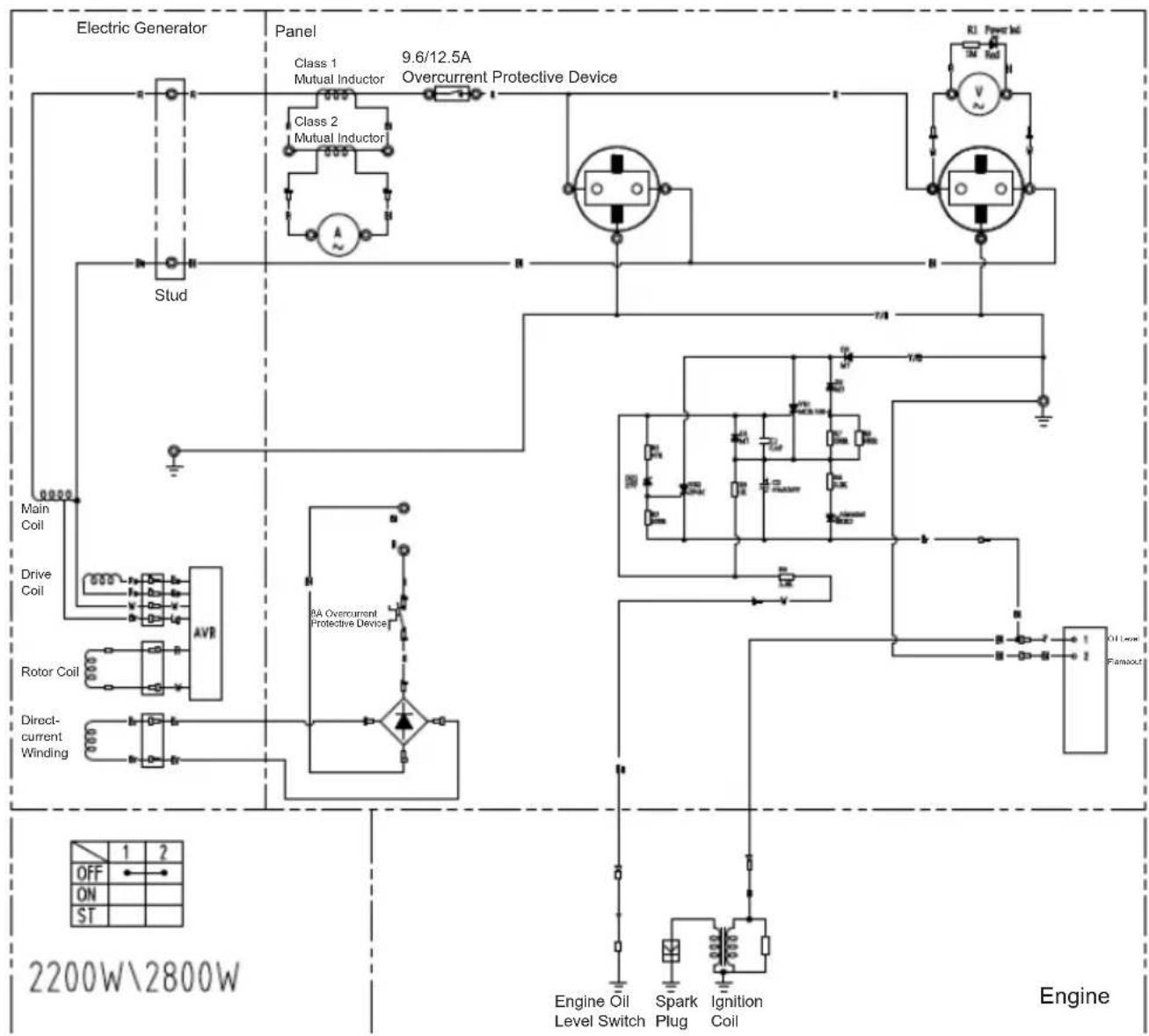
flowchart
graph TD
    A["Electric Generator"] --> B["Panel"]
    B --> C["Class 1 Mutual Inductor"]
    B --> D["Class 2 Mutual Inductor"]
    B --> E["19.5/24/26A Overcurrent Protective Device"]
    B --> F["16A Overcurrent Protective Device"]
    B --> G["16A Overcurrent Protective Device"]
    H["Main Coil"] --> I["Drive Coil"]
    I --> J["AVR"]
    K["Drive Coil"] --> L["Rotor Coil"]
    L --> M["Direct-current Winding"]
    N["Engine"] --> O["Carburetor Oil Cut-off Valve Level Switch"]
    N --> P["Engine Oil Fanoutput"]
    N --> Q["Engine Fuel Cut"]
    N --> R["Engine Charging Coil"]
    N --> S["Engine Starting Motor & Relay"]
    T["4500W\5500W\6000W"] --> U["OFF ON ST"]
    V["1"] --> W["Capacitor"]
    X["2"] --> Y["Engine Oil"]
    Z["3"] --> AA["Spark Plug"]
    AB["4"] --> AC["Ignition Coil"]
    AD["5"] --> AE["Charging Coil"]
    AF["6"] --> AG["Battery"]
    AH["7"] --> AI["Starting Motor & Relay"]
Note: Wiring is the same for the EG4550A, EG5550A, and EG6050A.
SPECIFICATIONS
| MODEL EG2250A EG2850A EG45 | 50A EG555 | 50A EG6050A | ||||
| Generator | Type Brush, 2-poles, single phase | |||||
| Voltage regulating system AVR type | ||||||
| AC OutputRated voltage-Frequency V-Hz | 230 - 50 | |||||
| Rated current A 8.7 11.3 17.4 21.7 24 | ||||||
| Rated output VA (W) 2,000 2,600 4,000 5,000 5 | 500 | |||||
| Maximum output VA (W) | 2,200 2,800 4,500 5 | 500 6,000 | ||||
| Rated power factor | 1.0 | |||||
| Safety device type | Circuit breaker | |||||
| DC OutputRated voltage V | 12 | |||||
| Rated current A | 8.3 | |||||
| Safety device type | Circuit breaker | |||||
| Engine | Model | 170F | 190F | |||
| Type | OHV 4-stroke single cylinder | |||||
| Displacement mL | 210 | 420 | ||||
| Fuel | Automotive Unleaded Gasoline | |||||
| Fuel tank capacity (Full) L | 15 | 25 | ||||
| Fuel tank capacity (regulated Fuel volume) L | 10 | 20 | ||||
| Engine oil capacity L | 0.6 | 1.1 | ||||
| Spark plug | Champion RN9YC | |||||
| Starting system | Recoil starter | Electric starter / Recoil | ||||
| Dimension | Length mm | 600 | 680 | |||
| Width mm | 442 | 550 | ||||
| Height mm | 450 | 550 | ||||
| Noise(according to 2000/14/EC) | Sound pressure level dB (A) | 75 (Uncertainty K=3) | ||||
| Sound power level dB (A) | 95 (Uncertainty K=3) | |||||
| Dry weight kg | 42 | 45 | 80 | 83 | 85 | |
| Gross weight Weight according to EPTA procedure 01/2003 kg | 49.8 52.8 | 95.5 98.5 | 100.5 | |||
ASSEMBLY
The Importance of Proper Assembly
Proper assembly is vital to operator safety and the machine reliability. Any error or oversight made by the person assembling or servicing a unit can easily result in faulty operation, damage to the machine, or injury to the operator.
WARNING:
Improper assembly can cause an unsafe condition that can lead to severe personal injury or loss of life. Follow the procedures and precautions in the assembly instructions carefully.
Some of the most important safety precautions are given below.
However, we cannot cover every conceivable hazard that can arise in performing this assembly, so please remember that only you can decide whether or not you should perform a given task.
WARNING:
Failure to properly follow instructions and precautions can cause severe personal injury or loss of life.
Follow the procedures and precautions in this manual carefully.
Important Safety Precautions
- Have a clear understanding of all basic shop safety practices and wear appropriate clothing and safety equipment. When performing this assembly, be especially careful of the following:
- Before beginning work, read the instructions and be sure you have the tools and skills required to perform the tasks safely.
- Make sure the engine is off before beginning any maintenance or repairs. This will help eliminate several potential hazards:
- Carbon monoxide poisoning from engine exhaust.
Operate outside away from open windows or doors.
- Burns from hot parts.
Let the engine and exhaust system cool before touching.
- Injury from moving parts.
Do not run the engine unless the instruction tells you to do so.
Even then, keep your hands, fingers, and clothing away. When any protective guard or shield has been removed, do not run the engine.
• To reduce the possibility of a fire or explosion, be careful when working around gasoline or batteries. Use only a non-flammable solvent, not gasoline, to clean parts. Keep all cigarettes, sparks, and flames away from all fuel-related parts.
Unpacking
- Take out the generator and the loose parts box from the carton.
- Check the loose parts against the contents list below.
Tools required: 12-mm wrench (2), pliers
Loose Parts (Wheel Kit and Handle) and Front Support (Only for model EG4550A, EG5550A, EG6050A)
Check all loose parts against the following list. Contact your dealer if any of the loose parts shown below are not included with the generator.
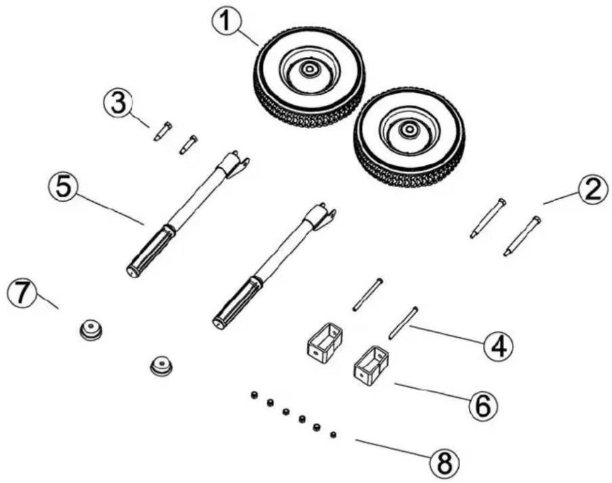
| No. Name Quantity | |
| 1 10-Inch Roller 2 | |
| 2 Wheel Axle 2 | |
| 3 Transport Handle Shaft 2 | |
| 4 M8 x 100 Bolt 2 | |
| 5 Transport Handle 2 | |
| 6 Front Stand 2 | |
| 7 Rubber Base 2 | |
| 8 M8 Flange Nut 6 |
Handle Installation (Fig. 24)
- Remove the two lugs in the pushrod inserted into the rack, and line up the hole on the pushrod with the hole on the rack. Next, insert the pushrod into the rack from the outside and then screw in the M8 flange bolt on the inside and tighten down the bolt.
TORQUE: 17 - 22 lbf•ft (24 - 29 N•m, 2.4 - 3.0 kgf•m)
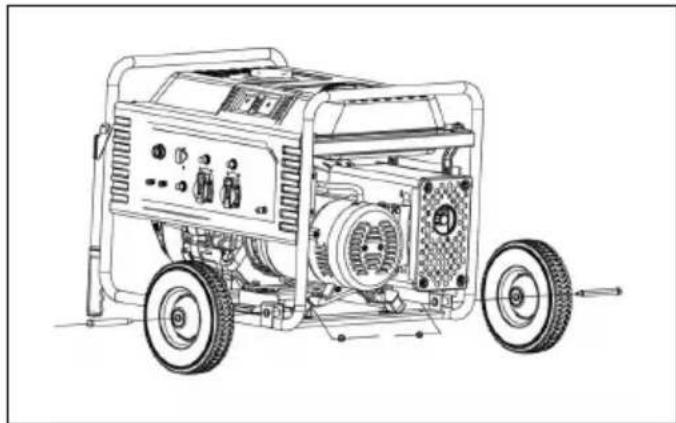
Wheel Kit Installation (Fig. 25)
- Line up the hole on the roller with the hole on the rack, insert the roller shaft into the rack from the outside, and then screw in the M8 flange bolt on the inside and tighten down the bolt.
TORQUE: 17 - 22 lbf•ft (24 - 29 N•m, 2.4 - 3.0 kgf•m)
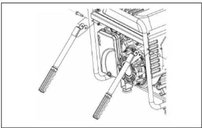
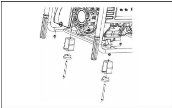
Fit the front stand (Fig. 26)
-
Insert an M8×100 bolt into the holes on the rubber blanket, front stand, and rack mounting plate.
-
Screw the M8 flange bolt onto the M8×100 bolt from the mounting plate and then tighten down the bolt.
Stopping the engine with remote control
-
Press the stop button.
-
Turn the engine switch on the generator to the "O (OFF)" position.
-
Turn the fuel valve lever on the generator to the "O (OFF)" position.
Battery Tray (Fig. 27)
NOTE:
Battery is not included. Use a battery (rating: 12V-10Ah, L x W x H: maximum 160 mm x 90 mm x 160 mm) available in the market.
-
Connect the black power line (ground electrode) on the electric generator to the negative electrode on the battery and the red power line to the positive electrode on the battery.
-
Place the battery connected to the power lines into the battery box on the rack.
-
Hang each of the two card buckles on the rubber belt onto one of the two hangers on the battery box.
WARNING:
Lead and lead compounds are used in battery posts, terminals, and related accessories. Always wash hands after handling.
Engine Oil (Fig. 13)
The generator is shipped WITHOUT OIL in the engine. Place the generator on a stable and level surface. Add enough of the recommended oil to bring the oil level to the top of the oil filler neck.
Use a 4-stroke motor oil that satisfies the requirements for API service category SJ or later (or equivalent).
Do not overfill the engine with oil. If the engine is overfilled, the excess oil may get transferred to the air cleaner housing and air filter.
WARRANTY SERVICE INFORMATION
CUSTOMER SERVICE INFORMATION
The personnel at the servicing dealership are trained professionals. They should be able to answer most
questions you may have. If there is a problem that your dealer does not solve to your satisfaction, please discuss it with the Service Manager or General Manager of the dealership. Almost all problems are solved in this way. If you are dissatisfied with the decision made by the dealership's management, contact the Makita Corporation.
For European countries only
EC Declaration of Conformity
We Makita Corporation as the responsible manufacturer declare that the following Makita machine(s):
Designation of Machine: Petrol Generator
Model No./ Type: EG2250A, EG2850A, EG4550A, EG5550A, EG6050A
Specifications: see "SPECIFICATIONS" table.
are of series production and
Conforms to the following European Directives: 2000/14/EC, 2004/108/EC, 2006/42/EC, 2006/95/EC
And are manufactured in accordance with the following standards or standardised documents:
EN12601, EN55012, EN61000, EN60204-1
The technical documentation is kept by:
Makita International Europe Ltd.
Technical Department,
Michigan Drive, Tongwell,
Milton Keynes, Bucks MK15 8JD, England
The conformity assessment procedure required by
Directive 2000/14/EC was in Accordance with annex VI. Notified Body:
AV TECHNOLOGY LTD
AVTECH House, Arkle Avenue
Stanley Green Trading Estate
Handforth, Cheshire
SK9 3RW, United Kingdom
Identification number 1067
Model EG2250A
Measured Sound Power Level: 94 dB (A)
Guaranteed Sound Power Level: 95 dB (A)
Model EG2850A, EG4550A, EG5550A, EG6050A
Measured Sound Power Level: 95 dB (A)
Guaranteed Sound Power Level: 96 dB (A)
27.12.2013

Tomoyasu Kato
Director
Makita Corporation
3-11-8, Sumiyoshi-cho,
Anjo, Aichi, 446-8502, JAPAN
(Champion), BPR5ES (NGK), W16EPR-U (DENSO)
flowchart
graph TD
    A["Electric Generator"] --> B["Stud"]
    B --> C["Main Coil"]
    B --> D["Drive Coil"]
    B --> E["Rotor Coil"]
    B --> F["Direct-current Winding"]
    G["Panel"] --> H["Class 1 Mutual Inductor"]
    G --> I["Class 2 Mutual Inductor"]
    G --> J["9.6/12.5A Overcurrent Protective Device"]
    K["Engine"] --> L["Engine Oil Level Switch"]
    K --> M["Spark Plug"]
    K --> N["Ignition Coil"]
    O["77A"] --> P["Overcurrent Protective Device"]
    Q["7A"] --> R["Overcurrent Protective Device"]
    S["7B"] --> T["Overcurrent Protective Device"]
    U["7C"] --> V["Overcurrent Protective Device"]
    W["7D"] --> X["Overcurrent Protective Device"]
    Y["7E"] --> Z["Overcurrent Protective Device"]
    AA["7F"] --> AB["Overcurrent Protective Device"]
    AC["7G"] --> AD["Overcurrent Protective Device"]
    AE["7H"] --> AF["Overcurrent Protective Device"]
2000/14/CE, 2004/108/CE, 2006/42/CE, 2006/95/CE
Technical Department,
Michigan Drive, Tongwell,
Milton Keynes, Bucks MK15 8JD, Angleterre
AVTECH House, Arkle Avenue
Stanley Green Trading Estate
Handforth, Cheshire
SK9 3RW, United Kingdom
Identification number 1067
Modèle EG2250A
3-11-8, Sumiyoshi-cho,
Anjo, Aichi, 446-8502, JAPON
flowchart
graph TD
    A["Electric Generator"] --> B["Stud"]
    B --> C["Main Coil"]
    B --> D["Drive Coil"]
    B --> E["Rotor Coil"]
    B --> F["Direct-current Winding"]
    G["Panel"] --> H["Class 1 Mutual Inductor"]
    G --> I["Class 2 Mutual Inductor"]
    G --> J["9.6/12.5A Overcurrent Protective Device"]
    K["Engine"] --> L["Engine Oil Level Switch"]
    K --> M["Spark Plug"]
    K --> N["Ignition Coil"]
    O["77A"] --> P["Overcurrent Protective Device"]
    Q["7A"] --> R["Overcurrent Protective Device"]
    S["7B"] --> T["Overcurrent Protective Device"]
    U["7C"] --> V["Overcurrent Protective Device"]
    W["7D"] --> X["Overcurrent Protective Device"]
    Y["7E"] --> Z["Overcurrent Protective Device"]
    AA["7F"] --> AB["Overcurrent Protective Device"]
    AC["7G"] --> AD["Overcurrent Protective Device"]
    AE["7H"] --> AF["Overcurrent Protective Device"]
Technical Department, Michigan Drive, Tongwell, Milton Keynes, Bucks MK15 8JD, England
AV TECHNOLOGY LTD AVTECH House, Arkle Avenue Stanley Green Trading Estate Handforth, Cheshire SK9 3RW, United Kingdom Identification number 1067
Modelle EG2250A
3-11-8, Sumiyoshi-cho,
Anjo, Aichi, 446-8502, JAPAN
AV TECHNOLOGY LTD AVTECH House, Arkle Avenue Stanley Green Trading Estate Handforth, Cheshire SK9 3RW, United Kingdom Identification number 1067
Modello EG2250A
3-11-8, Sumiyoshi-cho,
Anjo, Aichi, 446-8502, JAPAN
Aanbevolen bougies: RN9YC (Champion), BPR5ES (NGK), W16EPR-U (DENSO)
flowchart
graph TD
    subgraph "Electric Generator"
        A["Stud"] --> B["Class 1 Mutual Inductor"]
        B --> C["Class 2 Mutual Inductor"]
        C --> D["Overcurrent Protective Device"]
    end

    subgraph "Panel"
        E["Main Coil"] --> F["Drive Coil"]
        F --> G["AVR"]
        G --> H["RA Overcurrent Protective Device"]
        I["Direct-current Winding"] --> J["Engine Oil Level Switch"]
        K["Engine Oil Level Switch"] --> L["Spark Plug"]
        M["Engine Oil Level Switch"] --> N["Ignition Coil"]
    end

    subgraph "Engine"
        O["Rotor Coil"] --> P["Stud"]
        Q["Rotor Coil"] --> R["Stud"]
        S["Rotor Coil"] --> T["Stud"]
        U["Rotor Coil"] --> V["Stud"]
        W["Rotor Coil"] --> X["Stud"]
        Y["Rotor Coil"] --> Z["Stud"]
        AA["Rotor Coil"] --> AB["Stud"]
        AC["Rotor Coil"] --> AD["Stud"]
        AE["Rotor Coil"] --> AF["Stud"]
        AG["Rotor Coil"] --> AH["Stud"]
        AI["Rotor Coil"] --> AJ["Stud"]
        AK["Rotor Coil"] --> AL["Stud"]
        AM["Rotor Coil"] --> AN["Stud"]
        AO["Rotor Coil"] --> AP["Stud"]
        AQ["Rotor Coil"] --> AR["Stud"]
        AS["Rotor Coil"] --> AT["Stud"]
        AU["Rotor Coil"] --> AV["Stud"]
        AW["Rotor Coil"] --> AX["Stud"]
        AY["Rotor Coil"] --> AZ["Stud"]
        BA["Rotor Coil"] --> BB["Stud"]
        BC["Rotor Coil"] --> BD["Stud"]
        BE["Rotor Coil"] --> BF["Stud"]
        BG["Rotor Coil"] --> BH["Stud"]
        BI["Rotor Coil"] --> BJ["Stud"]
        BK["Rotor Coil"] --> BL["Stud"]
    end

    subgraph "Engine"
        M1["Engine Oil Level Switch"] --> N2["Spark Plug"]
        N2 --> O3["Ignition Coil"]
        O3 --> P4["Engine Oil Level Switch"]
        P4 --> Q5["Engine Oil Level Switch"]
        Q5 --> R6["Engine Oil Level Switch"]
        R6 --> S7["Engine Oil Level Switch"]
        S7 --> T7["Engine Oil Level Switch"]
        T7 --> U7["Engine Oil Level Switch"]
        U7 --> V7["Engine Oil Level Switch"]
        V7 --> W7["Engine Oil Level Switch"]
    end

    classDef label fill:#f9f,stroke:#333;
    class A,B,C,D,E,F,G,H,I,J,K,L,M,N,O,P,Q,R,S,T,U,V,W,X,Y,Z,N,N,N,N,N,N,N,N,N,N,N,N,N,N,N,N,N,N,N,N,N,N,N,N,N,N,N,N,N,N,N,N,N,N,N,N,N,N,N,N,N,N,N,N,N,N,N,N,N,N,N,N,N,N,N,N,N,N,N,N,N,N,N,N,N,N,N,N,N,N,N,N,N,N,N,N,N,N,N,N,N,N,N,N,N,N,N,N,N,N,N,N,N,N,N,N,N,N,N,N,n,Q,R,S,T,U,V,W,X,Y,Z,N,L,M,N,N,N,N,N,N,N,N,N,N,N,N,N,N,N,N,N,N,N,N,N,N,N,N,N,N,N,N,N,N,N,N,N,N,N,N,N,N,N,N,N,N,N,N,N,N,N,N,N,N,N,N,N,N,N,N,N,N,N,N,N,N,N,N,N,N,N,N,N,N,N,N,N,N,N,N,N,N,N,N,N,N,N,N,N,N,N,N,N,N,N,N,N,N,N,N,N,N,N-N,P,Q,R,S,T,U,V,W,X,Y,Z,n,L,M,n,Q,R,S,T,U,V,W,X,Y,Z,n,L,M,n,Q,R,S,T,U,V,W,X,Y,Z,n,L,M,n,Q,R,S,T,U,V,W,X,Y,Z,n,L,M,n,Q,R,S,T,U,V,W,X,Y,Z,n,L,M,n,Q,R,S,T,U,V,W,X,Y,Z,n,L,M,n,Q,R,S,T,U,V,W,X,Y,Z,n,L,M,n,Q,R,S,T,U,V,W,X,Y,Z,n,L,M,n,Q,r,s,t,U,v,W,X,Y,Z,n,L,M,n,Q,r,s,t,U,v,W,X,Y,Z,n,L,M,n,Q,r,s,t,U,v,W,X,Y,Z,n,L,M,n,Q,r,s,t,U,v,W,X,Y,Z,n,L,M,n,Q,r,s,t,U,v,W,X,Y,Z,n,L,M,n,Q,r,s,t,U,v,W,X,Y,Z,n,L,M,n,Q,r,s,t,U,v,W,X,Y,Z,n,L,M,n,Q,r,s,t,U,v,W,x,Y,Z,n,L,M,n,Q,r,s,t,U,v,W,X,Y,Z,n,L,M,n,Q,r,s,t,U,v,W,X,Y,Z,n,L,M,n,Q,r,s,t,U,v,W,X,Y,Z,n,L,M,n,Q,r,s,t,U,v,W,X,Y,Z,n,L,M,n,Q,r,s,t,U,v,W,X,Y,Z,n,L,M,n,Q,r,s,t,U,v,W,X,Y,Z,n,L,M,n,Q,r,s,t,U,v,W,X,Y,z,n,L,M,n,Q,r,s,t,U,v,W,X,Y,Z,n,L,M,n,Q,r,s,t,U,v,W,X,Y,Z,n,L,M,n,Q,r,s,t,U,v,W,X,Y,Z,n,L,M,n,Q,r,s,t,U,v,W,X,Y,Z,n,L,M,n,Q,r,s,t,U,v,W,X,Y,Z,n,L,M,n,Q,r,s,t,U,v,W,X,Y,Z,n,L,M,n,Q,r,s,t,U,v,W,X,Y,Z,n,l,m,n,Q,r,s,t,U,v,W,X,Y,Z,n,l,m,n,Q,r,s,t,U,v,W,X,Y,Z,n,l,m,n,Q,r,s,t,U,v,W,X,Y,Z,n,l,m,n,Q,r,s,t,U,v,W,X,Y,Z,n,l,m,n,Q,r,s,t,U,v,W,X,Y,Z,n,l,m,n,Q,r,s,t,U,v,W,X,Y,Z,n,l,m,n,Q,r,s,t,U,v,W,X,Y,Z,n,l,m,n,q,r,s,t,U,v,W,X,Y,Z,n,l,m,n,Q,r,s,t,U,v,W,X,Y,Z,n,l,m,n,Q,r,s,t,U,v,W,X,Y,Z,n,l,m,n,Q,r,s,t,U,v,W,X,Y,Z,n,l,m,n,Q,r,s,t,U,v,W,X,Y,Z,n,l,m,n,Q,r,s,t,U,v,W,X,Y,Z,n,l,m,n,Q,r,s,t,U,v,W,X,Y,Z,n,l,m,n,Q,r,p,u,v,w,x,y,z,u,k,l,m,u,k,l,u,k,l,u,k,l,u,k,l,u,k,l,u,k,l,u,k,l,u,k,l,u,k,l,u,k,l,u,k,l,u,k,l,u,k,l,u,k,l,u,k,l,u,k,l,u,k,l,u,k,l,u,k,l,u,k,l,u,k,l,u,k,l,u,k,l,u,k,l,u,k,l,u,k,l,u,k,l,u,k,l,u,k,l,u,k,l,u,k,l,u,k,l,u,k,l,u,k,l,a,b,c,d,e,f,g,h,i,j,k,l,m,m,m,m,m,m,m,m,m,m,m,m,m,m,m,m,m,m,m,m,m,m,m,m,m,m,m,m,m,m,m,m,m,m,m,m,m,m,m,m,m,m,m,m,m,m,m,m,m,m,m,m,m,m,m,m,m,m,m,m,m,m,m,m,m,m,m,m,m,m,m,m,m,m,m,m,m,m,m,m,m,m,m,m,m,m,m,m,m,m,m,m,m,m,m,m,m,m,m,mm,p,u,v,w,x,y,z,u,k,l,m,m,m,m,m,m,m,m,m,m,m,m,m,m,m,m,m,m,m,m,m,m,m,m,m,m,m,m,m,m,m,m,m,m,m,m,m,m,m,m,m,m,m,m,m,m,m,m,m,m,m,m,m,m,m,m,m,m,m,m,m,m,m,m,m,m,m,m,m,m,m,m,m,m,m,m,mm,p,u,v,w,x,y,z,u,k,l,m,mm,mm,mm,mm,mm,mm,mm,mm,mm,mm,mm,mm,mm,mm,mm,mm,mm,mm,mm,mm,mm,mm,mm,mm,mm,mm,mm,mm,mm,mm,mm,mm,mm,mm,mm,mm,mm,mm,mm,mm,mm,mm,mm,mm,mm,mm,mm,mm,mm,mm,rm,p,u,v,w,x,y,z,u,k,l,\n\n\n\n\n\n\n\n\n\n\n\n\n\n\n\n\n\n\n\n\n\n\n\n\n\n\n\n\n\n\n\n\n\n\n\n\n\n\n\n\n\n\n\n\n\n\n\n\n\n\n\n\n\n\n\n\n\n\n\n\n\n\n\n\n\n\n\n\n\n\n\n\n\n\n\n\n\n\n\n\n\n\n\n\n\n\n\n\n\n\n\n\n\n\n\n\n\n\n\n\n\n\n\n\n\n\n\n\n\n\n\n\n\n\n\n\n\n\n\n\n\n\n\n\n\n\n\n\n\n\n\n\n\n\n\n\n\n\n\n\n\n\n\n\n\n\n\n\n\n\n\n\n\n\n\n\n\n\n\n\n\n\n\n\n\n\n\n\n\n\n\n\n\n\n\n\n\n\n\n\n\n\n\n\n\n\n\n\n\n\n\n\n\n\n\n\n\n\n\n<ecel><nl>
Michigan Drive, Tongwell,
Milton Keynes, Bucks MK15 8JD, Engeland
AV TECHNOLOGY LTD AVTECH House, Arkle Avenue Stanley Green Trading Estate Handforth, Cheshire SK9 3RW, United Kingdom Identification number 1067
Tomoyasu Kato Director
Makita Corporation 3-11-8, Sumiyoshi-cho, Anjo, Aichi, 446-8502, JAPAN
Technical Department, Michigan Drive, Tongwell,
Milton Keynes, Bucks MK15 8JD, Inglaterra
AV TECHNOLOGY LTD AVTECH House, Arkle Avenue Stanley Green Trading Estate Handforth, Cheshire SK9 3RW, United Kingdom Identification number 1067
Modelo EG2250A
3-11-8, Sumiyoshi-cho,
Anjo, Aichi, 446-8502, JAPAN
Makita Corporation
3-11-8, Sumiyoshi-cho, Anjo, Aichi 446-8502 Japan
EG2250A-6L-0913 www.makita.com

- WARNING:
- ABOUT SAFETY
- DANGER:
- CAUTION:
- GENERATOR SAFETY
- SYMBOLS and MEANINGS
- IMPORTANT SAFETY INFORMATION
- Responsibilities of the Operator
- Carbon Monoxide Hazards
- Electric Shock Hazards
- Fire and Burn Hazards
- Other Safety Information:
- COMPONENTS (Fig. 1)
- CONTROL PANEL (Fig. 2 & Fig. 3)
- CONTROLS
- Engine Switch (Fig. 4)
- Key position:
- Starter Grip (Fig. 5)
- NOTICE:
- Fuel Valve Lever (Fig. 6)
- Choke Rod (Fig. 7)
- Ground Terminal (Fig. 8)
- DC Terminals
- DC Circuit Protector (Fig. 9)
- Oil Alert System (Fig. 14)
- AC Circuit Breaker (Fig. 10)
- AC Circuit Protector (EG4550A, EG5550A, EG6050A only) (Fig. 11)
- GENERATOR USE
- Connections to a Building's Electrical System
- Ground System
- AC Applications
- AC Operation (Fig. 12)
- DC Operation
- Connecting the battery charging cables:
- Disconnecting the battery cables:
- High Altitude Operation
- Check Engine Fuel (Fig. 14)
- Recommended Fuels
- STARTING/STOPPING THE ENGINE
- Starting the Engine
- Stopping the Engine
- In an emergency:
- In normal use:
- MAINTENANCE
- The Importance of Maintenance
- Maintenance Safety
- Safety Precautions
- Engine Oil Change (Fig. 15)
- Air Cleaner Service (Fig. 16 & Fig. 17)
- Fuel Sediment Cup Cleaning
- Spark Plug Service (Fig. 18 & Fig. 19)
- Spark Arrester Maintenance (country specific) (Fig. 20)
- STORAGE
- Storage Preparation
- Cleaning
- Fuel
- Draining the Fuel Tank and Carburetor (Fig. 21)
- Engine Oil (Fig. 22)
- Storage Precautions
- Removal from Storage
- TRANSPORTING (Fig. 23)
- TROUBLESHOOTING
- TECHNICAL INFORMATION
- Emission Control System Information
- Source of Emissions
- Tampering and Altering
- Problems That May Affect Emissions
- Replacement Parts
- ASSEMBLY
- The Importance of Proper Assembly
- Important Safety Precautions
- Unpacking
- Loose Parts (Wheel Kit and Handle) and Front Support (Only for model EG4550A, EG5550A, EG6050A)
- Handle Installation (Fig. 24)
- Wheel Kit Installation (Fig. 25)
- Fit the front stand (Fig. 26)
- Stopping the engine with remote control
- Battery Tray (Fig. 27)
- NOTE:
- Engine Oil (Fig. 13)
- WARRANTY SERVICE INFORMATION
- CUSTOMER SERVICE INFORMATION
- For European countries only
- EC Declaration of Conformity
- Makita Corporation
Brand : MAKITA
Model : EG2850A
Category : Generator