NEC3240FW - Tumble drier AMANA - Free user manual and instructions
Find the device manual for free NEC3240FW AMANA in PDF.
Frequently Asked Questions - NEC3240FW AMANA
User questions about NEC3240FW AMANA
0 question about this device. Answer the ones you know or ask your own.
Ask a new question about this device
Download the instructions for your Tumble drier in PDF format for free! Find your manual NEC3240FW - AMANA and take your electronic device back in hand. On this page are published all the documents necessary for the use of your device. NEC3240FW by AMANA.
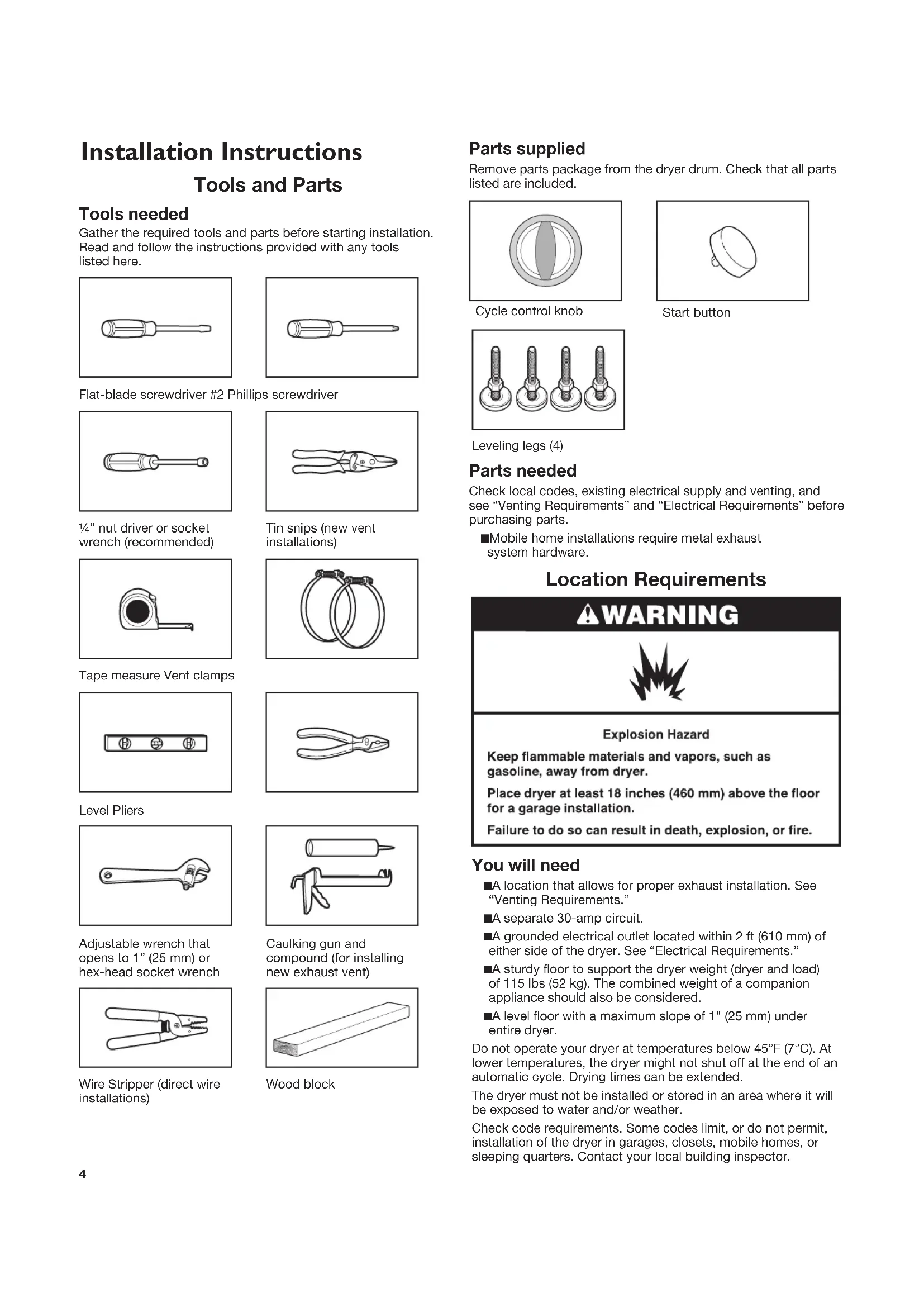
USER MANUAL NEC3240FW AMANA
Sécheuse Électrique compacte 240 volts Guide d’utilisation et d’entretien Para una versión de estas instrucciones en español, visite www.amana.com2 Dryer Safety34 Installation Instructions Tools and Parts Tools needed Gather the required tools and parts before starting installation. Read and follow the instructions provided with any tools listed here. Flat-blade screwdriver #2 Phillips screwdriver ¼” nut driver or socket wrench (recommended) Tin snips (new vent installations) Tape measure Vent clamps Level Pliers Adjustable wrench that opens to 1” (25 mm) or hex-head socket wrench Caulking gun and compound (for installing new exhaust vent) Wire Stripper (direct wire installations) Wood block Parts supplied Remove parts package from the dryer drum. Check that all parts listed are included. Cycle control knob Start button Leveling legs (4) Parts needed Check local codes, existing electrical supply and venting, and see “Venting Requirements” and “Electrical Requirements” before purchasing parts. ■ Mobile home installations require metal exhaust system hardware. Location Requirements You will need ■ A location that allows for proper exhaust installation. See “Venting Requirements.” ■ A separate 30-amp circuit. ■ A grounded electrical outlet located within 2 ft (610 mm) of either side of the dryer. See “Electrical Requirements.” ■ A sturdy floor to support the dryer weight (dryer and load) of 115 lbs (52 kg). The combined weight of a companion appliance should also be considered. ■ A level floor with a maximum slope of 1" (25 mm) under entire dryer. Do not operate your dryer at temperatures below 45°F (7°C). At lower temperatures, the dryer might not shut off at the end of an automatic cycle. Drying times can be extended. The dryer must not be installed or stored in an area where it will be exposed to water and/or weather. Check code requirements. Some codes limit, or do not permit, installation of the dryer in garages, closets, mobile homes, or sleeping quarters. Contact your local building inspector.5 Installation Clearances The location must be large enough to allow the dryer door to open fully. Dryer Dimensions Front View
/8" (303 mm) Minimum spacing for recessed area and closet installation The following dimensions shown are for the minimum spacing allowed when the dryer is to be operated with, or without, the Stack Stand Kit. To purchase a Stack Stand Kit, see “Assistance or Service.” ■ Additional spacing should be considered for ease of installation and servicing. ■ Additional clearances might be required for wall, door, and floor moldings. ■ For closet installation with a door, minimum ventilation openings in the top and bottom of the door are required. Louvered doors with equivalent ventilation openings are acceptable. ■ Companion appliance spacing should also be considered. Recessed or closet installation - Dryer only
/2"*(140 mm) A. Side view - closet or confined area B. Recessed area *Most installations require a minimum 5½" (140 mm) clearance behind the dryer for the exhaust vent with elbows. See “Venting Requirements.” Recessed or closet installation - Stacked DRYER WASHER
1"*(25 mm) 3"*(76 mm)48 in. * (309.7 cm ) 24 in. * (154.8 cm ) 3"*(76 mm) A. Recessed area B. Side view - closet or confined area C. Closet door with vents Mobile Home - Additional Location Requirements This dryer is suitable for mobile home installations. The installation must conform to the Manufactured Home Construction and Safety Standard, Title 24 CFR, Part 3280 (formerly the Federal Standard for Mobile Home Construction and Safety, Title 245, HUD Part 280) or Standard CAN/CSA- Z240 MH. Mobile home installations require: Metal exhaust system hardware, which is available for purchase from your dealer. Special provisions must be made in mobile homes to introduce outside air into the dryer. The opening (such as a nearby window) should be at least twice as large as the dryer exhaust opening.6 Electrical Requirements It is your responsibility ■ To contact a qualified electrical installer. ■ To be sure that the electrical connection is adequate and in conformance with the National Electrical Code, ANSI/NFPA 70-latest edition and all local codes and ordinances. The National Electrical Code requires a 4-wire supply connection for homes built after 1996, dryer circuits involved in remodeling after 1996, and all mobile home installations. A copy of the above code standards can be obtained from: National Fire Protection Association, One Batterymarch Park, Quincy, MA 02269. ■ To supply the required 3 or 4 wire, single phase, 120/240 volt, 60 Hz., AC only electrical supply (or 3 or 4 wire, 120/208 volt electrical supply, if specified on the serial/rating plate) on a separate 30-amp circuit, fused on both sides of the line. A time-delay fuse or circuit breaker is recommended. Connect to an individual branch circuit. Do not have a fuse in the neutral or grounding circuit. ■ Do not use an extension cord. ■ If codes permit and a separate ground wire is used, it is recommended that a qualified electrician determine that the ground path is adequate. Electrical Connection To properly install your dryer, you must determine the type of electrical connection you will be using and follow the instructions provided for it here. ■ If local codes do not permit the connection of a neutral ground wire to the neutral wire, see “Optional 3-wire connection” in the “Electrical Connection” section. ■ This dryer is manufactured ready to install with a 3-wire electrical supply connection. The neutral ground wire is permanently connected to the neutral conductor (white wire) within the dryer. If the dryer is installed with a 4-wire electrical supply connection, the neutral ground wire must be removed from the external ground conductor screw (green screw), and secured under the neutral terminal (center or white wire) of the terminal block. When the neutral ground wire is secured under the neutral terminal (center or white wire) of the terminal block, the dryer cabinet is isolated from the neutral conductor. ■ A 4-wire power supply connection must be used when the appliance is installed in a location where grounding through the neutral conductor is prohibited. Grounding through the neutral is prohibited for (1) new branch-circuit installations, (2) mobile homes, (3) recreational vehicles, and (4) areas where local codes prohibit grounding through the neutral conductors. If using a power supply cord: Use a UL listed power supply cord kit marked for use with clothes dryers. The kit should contain: ■ A UL listed 30-amp power supply cord, rated 120/240 volt minimum. The cord should be type SRD or SRDT and be at least 4 ft (1.22 m) long. The wires that connect to the dryer must end in ring terminals or spade terminals with upturned ends. ■ A UL listed strain relief. If your outlet looks like this: 4-wire receptacle (14-30R) Then choose a 4-wire power supply cord with ring or spade terminals and UL listed strain relief. The 4-wire power supply cord, at least 4 ft (1.22 m) long, must have four 10-gauge copper wires and match a 4-wire receptacle of NEMA Type 14-30R. The ground wire (ground conductor) may be either green or bare. The neutral conductor must be identified by a white cover. If your outlet looks like this: 3-wire receptacle (10-30R) Then choose a 3-wire power supply cord with ring or spade terminals and UL listed strain relief. The 3-wire power supply cord, at least 4 ft (1.22 m) long, must have three 10-gauge copper wires and match a 3-wire receptacle of NEMA Type 10-30R. If connecting by direct wire: Power supply cable must match power supply (4-wire or 3-wire) and be: ■ Flexible armored cable or nonmetallic sheathed copper cable (with ground wire), protected with flexible metallic conduit. All current-carrying wires must be insulated. ■ 10-gauge solid copper wire (do not use aluminum). ■ At least 5 ft (1.52 m) long.7
1. Disconnect power.
2. Remove the hold-down screw and terminal block cover.
A. Terminal block cover B. External ground conductor screw C. Center terminal block screw D. Hold-down screw location E. Neutral ground wire F. Hole below terminal block opening
3. Install strain relief.
Electrical Connection Direct Wire Power Supply Cord Style 1: Power supply cord strain relief ■ Remove the screws from a ¾" (19 mm) UL listed strain relief (UL marking on strain relief). Put the tabs of the two clamp sections into the hole below the terminal block opening so that one tab is pointing up and the other is pointing down, and hold in place. Tighten strain relief screws just enough to hold the two clamp sections together.
■ Put power supply cord through the strain relief. Be sure that the wire insulation on the power supply cord is inside the strain relief. The strain relief should have a tight fit with the dryer cabinet and be in a horizontal position. Do not further tighten strain relief screws at this point. Style 2: Direct wire strain relief ■ Unscrew the removable conduit connector and any screws from a ¾" (19 mm) UL listed strain relief (UL marking on strain relief). Put the threaded section of the strain relief through the hole below the terminal block opening. Reaching inside the terminal block opening, screw the removable conduit connector onto the strain relief threads.
A. Removable conduit connector B. Hole below terminal block opening C. Strain relief threads ■ Put direct wire cable through the strain relief. The strain relief should have a tight fit with the dryer cabinet and be in a horizontal position. Tighten strain relief screw against the direct wire cable.
4. Now complete installation following instructions for your type
of electrical connection: 4-wire (recommended) 3-wire (if 4-wire is not available) Electrical Connection Options If your home has: And you will be connecting to: Go to Section 4-wire receptacle (NEMA Type 14-30R) A UL listed, 120/240-volt minimum, 30-amp, dryer power supply cord* 4-wire connection: Power supply cord 4-wire direct (127 mm) A fused disconnect or circuit breaker box* 4-wire connection: Direct Wire 3-wire receptacle (NEMA type 10-30R) A UL listed, 120/240-volt minimum, 30-amp, dryer power supply cord* 3-wire connection: Power supply cord 3-wire direct 3¹₂" (89 mm) A fused disconnect or circuit breaker box* 3-wire connection: Direct Wire *If local codes do not permit the connection of a cabinet-ground conductor to the neutral wire, go to “Optional 3-wire connection” section. 4-wire connection: Power Supply Cord IMPORTANT: A 4-wire connection is required for mobile homes and where local codes do not permit the use of 3-wire connections.
A. 4-wire receptacle (NEMA type 14-30R) B. 4-prong plug C. Ground prong D. Neutral prong E. Spade terminals with upturned ends F. ¾" (19 mm) UL listed strain relief G. Ring terminals
1. Remove center terminal block screw.9
2. Remove neutral ground wire from external ground conductor
screw. Connect neutral ground wire and the neutral wire (white or center wire) of power supply cord under center terminal block screw. Tighten screw.
A. External ground conductor screw - Dotted line shows position of NEUTRAL ground wire before being moved to center terminal block screw B. Center terminal block screw C. Neutral wire (white or center wire) D. ¾" (19 mm) UL listed strain relief E. Neutral ground wire
3. Connect ground wire (green or bare) of power supply cord to
external ground conductor screw. Tighten screw.
A. External ground conductor screw B. Center terminal block screw C. Neutral wire (white or center wire) D. ¾" (19 mm) UL listed strain relief E. Neutral ground wire F. Ground wire (green or bare) of power supply cord
4. Connect the other wires to outer terminal block screws.
5. Tighten strain relief screws.
6. Insert tab of terminal block cover into slot of dryer rear panel.
Secure cover with hold-down screw.
7. You have completed your electrical connections. Now go to
“Venting Requirements.” 4-wire connection: Direct Wire IMPORTANT: A 4-wire connection is required for mobile homes and where local codes do not permit the use of 3-wire connections. Direct wire cable must have 5 ft (1.52 m) of extra length so dryer can be moved if needed. Strip 5" (127 mm) of outer covering from end of cable, leaving bare ground wire at 5" (127 mm). Cut 1½" (38 mm) from 3 remaining wires. Strip insulation back 1" (25 mm). Shape ends of wires into a hook shape. 1"(25 mm)
(127 mm) When connecting to the terminal block, place the hooked end of the wire under the screw of the terminal block (hook facing right), squeeze hooked end together and tighten screw, as shown.
1. Remove center terminal block screw.
2. Remove neutral ground wire from external ground conductor
screw. Connect neutral ground wire and place the hooked end (hook facing right) of the neutral wire (white or center wire) of direct wire cable under the center screw of the terminal block. Squeeze hooked ends together. Tighten screw.
A. External ground conductor screw - Dotted line shows position of NEUTRAL ground wire before being moved to center terminal block screw B. Center terminal block screw C. Neutral wire (white or center wire) D. ¾" (19 mm) UL listed strain relief E. Neutral ground wire10
3. Connect ground wire (green or bare) of power supply cable to
external ground conductor screw. Tighten screw.
A. External ground conductor screw B. Center terminal block screw C. Neutral wire (white or center wire) D. ¾" (19 mm) UL listed strain relief E. Neutral ground wire F. Ground wire (green or bare) of power supply cable
4. Place the hooked ends of the other power supply cable wires
under the outer terminal block screws (hooks facing right). Squeeze hooked ends together. Tighten screws.
5. Tighten strain relief screws.
6. Insert tab of terminal block cover into slot of dryer rear panel.
Secure cover with hold-down screw.
7. You have completed your electrical connections. Now go to
“Venting Requirements.” 3-wire connection: Power Supply Cord Use where local codes permit connecting cabinet-ground conductor to neutral wire:
A. 3-wire receptacle (NEMA type 10-30R) B. 3-wire plug C. Neutral prong D. Spade terminals with up turned ends E. ¾" (19 mm) UL listed strain relief F. Ring terminals G. Neutral (white or center wire)
1. Loosen or remove center terminal block screw.
2. Connect neutral wire (white or center wire) of power supply
cord to the center terminal screw of the terminal block. Tighten screw.
A. Neutral ground wire B. External ground conductor screw C. Center terminal block screw D. Neutral wire (white or center wire) E. ¾" (19 mm) UL listed strain relief
3. Connect the other wires to outer terminal block screws.
4. Tighten strain relief screws.
5. Insert tab of terminal block cover into slot of dryer rear panel.
Secure cover with hold-down screw.
6. You have completed your electrical connections. Now go to
“Venting Requirements.” 3-wire connection: Direct Wire Use where local codes permit connecting cabinet-ground conductor to neutral wire. Direct wire cable must have 5 ft (1.52 m) of extra length so dryer can be moved if needed. Strip 3½" (89 mm) of outer covering from end of cable. Strip insulation back 1" (25 mm). If using 3-wire cable with ground wire, cut bare wire even with outer covering. Bend ends of wires into a hook shape. 1"(25 mm) 3½" (89 mm) When connecting to the terminal block, place the hooked end of the wire under the screw of the terminal block (hook facing right), squeeze hooked end together and tighten screw, as shown.11
of power supply cable under the center screw of terminal block (hook facing right). Squeeze hooked end together. Tighten screw.
A. Neutral ground wire B. External ground conductor screw C. Center terminal block screw D. Neutral wire (white or center wire) E. ¾" (19 mm) UL listed strain relief
3. Place the hooked ends of the other power supply cable wires
under the outer terminal block screws (hooks facing right). Squeeze hooked ends together. Tighten screws.
4. Tighten strain relief screw.
5. Insert tab of terminal block cover into slot of dryer rear panel.
Secure cover with hold-down screw.
6. You have completed your electrical connections. Now go to
“Venting Requirements.” Optional 3-wire connection Use for direct wire or power supply cord where local codes do not permit connecting cabinet-ground conductor to neutral wire.
1. Remove center terminal block screw.
2. Remove neutral ground wire from external ground conductor
screw. Connect neutral ground wire and the neutral wire (white or center wire) of power supply cord/cable under center terminal block screw. Tighten screw.
A. External ground conductor screw B. Neutral ground wire C. Center terminal block screw D. Neutral wire (white or center wire) E. ¾" (19 mm) UL listed strain relief F. Grounding path determined by a qualified electrician
3. Connect the other wires to outer terminal block screws.
4. Tighten strain relief screws.
5. Insert tab of terminal block cover into slot of dryer rear panel.
Secure cover with hold-down screw.
6. Connect a separate copper ground wire from the external
ground conductor screw to an adequate ground.12 Venting Requirements
WARNING: To reduce the risk of fire, this dryer MUST BE
EXHAUSTED OUTDOORS. IMPORTANT: Observe all governing codes and ordinances. Dryer exhaust must not be connected into any gas vent, chimney, wall, ceiling, attic, crawlspace, or a concealed space of a building. Only rigid or flexible metal vent shall be used for exhausting. 4" (102 mm) heavy metal exhaust vent ■ Only a 4" (102 mm) heavy metal exhaust vent and clamps may be used. ■ Do not use plastic or metal foil vent. Rigid metal vent: ■ Recommended for best drying performance and to avoid crushing and kinking. Flexible metal vent: (Acceptable only if accessible to clean) ■ Must be fully extended and supported in final dryer location. ■ Remove excess to avoid sagging and kinking that may result in reduced airflow and poor performance. ■ Do not install in enclosed walls, ceilings, or floors. ■ The total length should not exceed 7¾ ft. (2.4 m). NOTE: If using an existing vent system, clean lint from entire length of the system and make sure exhaust hood is not plugged with lint. Replace plastic or metal foil vents with rigid metal or flexible metal vents. Review “Vent System Chart” and, if necessary, modify existing vent system to achieve best drying performance. Exhaust hoods: ■ Must be at least 12" (305 mm) from ground or any object that may obstruct exhaust (such as flowers, rocks, bushes, or snow). Recommended Style: Louvered hood Box hood Acceptable Style: Angled hood Elbows 45° elbows provide better airflow than 90° elbows. Good Better Clamps ■ Use clamps to seal all joints. ■ Exhaust vent must not be connected or secured with screws or other fastening devices that extend into the interior of the duct, because they can catch lint. Do not use duct tape. Improper venting can cause moisture and lint to collect indoors, which may result in: Moisture damage to woodwork, furniture, paint, wallpaper, carpets, etc. Housecleaning problems and health problems. Venting13 Plan Vent System Choose your exhaust installation type Recommended exhaust installations: Typical installations vent the dryer from the rear of the dryer. Other installations are possible.
A. Exhaust hood B. Flexible metal or rigid metal vent C. Elbow Alternate installations for close clearances: Venting systems come in many varieties. Select the type best for your installation. Two close-clearance installations are shown. Refer to the manufacturer’s instructions. A B A. Over-the-top installation (also available with one offset elbow) B. Periscope installation NOTE: The following kits for close clearance alternate installations are available for purchase. For information on ordering, see “Assistance or Service.” ■ Over-the-Top Installation: Part Number 4396028 ■ Periscope Installation (for use with dryer vent to wall vent mismatch): Part Number 4396037 - for mismatch of 0" (0 mm) to 18" (457 mm) Part Number 4396011 - for mismatch of 18" (457 mm) to 29" (737 mm) Part Number 4396014 - for mismatch of 29" (737 mm) to 50" (1.27 m) Special provisions for mobile home installations The exhaust vent must be securely fastened to a noncombustible portion of the mobile home structure and must not terminate beneath the mobile home. Terminate the exhaust vent outside. Determine vent path ■ Select the route that will provide the straightest and most direct path outdoors. ■ Plan the installation to use the fewest number of elbows and turns. ■ When using elbows or making turns, allow as much room as possible. ■ Bend vent gradually to avoid kinking. ■ Use the fewest 90° turns possible. Determine vent length and elbows needed for best drying performance ■ Use the “Vent System Chart” below to determine type of vent material and hood combinations acceptable to use. NOTE: Do not use vent runs longer than those specified in the Vent system chart. Exhaust systems longer than those specified will: ■ Shorten the life of the dryer. ■ Reduce performance, resulting in longer drying times and increased energy usage. The “Vent System Chart” provides venting requirements that will help to achieve the best drying performance. Vent System Chart Number of 90° turns or elbows Type of vent Box or louvered hoods Angled hoods
1. Install exhaust hood.
12" min. (305 mm) 12" min. (305 mm) Install exhaust hood and use caulking compound to seal exterior wall opening around exhaust hood.
2. Connect vent to exhaust hood.
Vent must fit inside exhaust hood. Secure vent to exhaust hood with 4" (102 mm) clamp. Run vent to dryer location. Use the straightest path possible. See “Determine vent path” in “Plan Vent System.” Avoid 90° turns. Use clamps to seal all joints. Do not use duct tape, screws, or other fastening devices that extend into the interior of the vent to secure vent, because they can catch lint. Install Leveling Legs
1. To avoid damaging floor, use a large flat piece of cardboard
from dryer carton. Place cardboard under entire back edge of the dryer.
2. Firmly grasp dryer body and gently lay dryer on cardboard.
3. Start to screw legs into holes by hand. Use a wrench to finish
turning legs. They should stick out about 1" (25 mm).
4. Place a carton corner post from dryer packaging under each
of the 2 dryer back corners. Stand the dryer up. Slide the dryer on the corner posts until it is close to its final location. Leave enough room to connect the exhaust vent. Connect Vent
1. Connect vent to exhaust outlet.
Using a 4" (102 mm) clamp, connect vent to exhaust outlet in dryer. If connecting to existing vent, make sure the vent is clean. Dryer vent must fit over dryer exhaust outlet and inside exhaust hood. Check that vent is secured to exhaust hood with a 4" (102 mm) clamp.
2. Move dryer into its final location. Avoid crushing or kinking
3. Once exhaust vent connection is made, remove corner posts
and cardboard.15 Level Dryer
1. Check levelness of dryer. Check levelness first side to side,
then front to back. Not Level LEVEL Not Level
2. Tighten and adjust leveling legs.
If dryer is not level, prop the dryer up using a wood block. Use a wrench to adjust the legs up or down and check again for levelness. Once legs are level, make sure all four legs are snug against the floor before tightening them. Complete Installation
1. Check that all parts are now installed. If there is an extra part,
go back through the steps to see what was skipped.
2. Check that you have all of your tools.
3. Dispose of/recycle all packaging materials.
4. Check dryer’s final location. Be sure vent is not crushed
5. Check that dryer is on a level surface.
6. For power supply cord installation, plug into an outlet. For
direct wire installation, turn on power.
7. Remove film on the console and any tape remaining on dryer.
Remove tape from lint screen (located on inside back wall of dryer).
8. Read “Dryer Use.”
9. Wipe dryer drum interior thoroughly with a damp cloth to
10. To test the dryer, set the dryer on a full heat cycle (not an air
cycle) for 20 minutes and start the dryer. If the dryer will not start, check the following: ■ Controls are set in a running or “On” position. ■ START button has been firmly pressed. ■ Dryer is plugged into an outlet and/or electrical supply is on. ■ Household fuse is intact and tight, or circuit breaker has not tripped. ■ Dryer door is closed.
11. When the dryer has been running for 5 minutes, open the
dryer door and feel for heat. If you feel heat, cancel cycle and close the door. If you do not feel heat, check the following: ■ Controls are set on a heated cycle, not an air cycle. NOTE: You may notice an odor when dryer is first heated. This odor is common when the heating element is first used. The odor will go away.16
WARNING: To reduce the risk of fire, electric shock, or injury to
persons, read the IMPORTANT SAFETY INSTRUCTIONS before operating this appliance. Before using your dryer, wipe the dryer drum with a damp cloth to remove dust from storing and shipping.
1. Clean the lint screen before each load. See “Cleaning the Lint
2. Load clothes loosely into the dryer and close the door. Do not
pack the dryer. Allow space for clothes to tumble freely. Using Your Dryer Starting Your Dryer
3. Turn the Cycle Control knob to the recommended cycle for the
type of load being dried. Use the Energy Preferred setting to dry most heavyweight and medium weight loads. See “Drying, Cycle, and Temperature Tips.”
Stopping and Restarting You can stop your dryer anytime during a cycle. To stop your dryer Open dryer door or turn Cycle Control knob to OFF. NOTE: The Cycle Control knob should point to an Off area when dryer is not in use. To restart your dryer
2. Select a new cycle and temperature (if desired).
3. Press START button.17
Loading Load clothes loosely into the dryer. Do not overload the dryer. Allow space for clothes to tumble freely. The following chart shows the maximum load you can place in your compact dryer. Expect longer drying times. Heavy work clothes 2 pair of pants, 3 work shirts Delicates 1 camisole, 2 slips, 4 undergarments, 1 set of sleepwear, 1 half slip Towels 9 bath towels; or 6 bath towels, 3 hand towels, 6 washcloths Mixed load 2 pillowcases, 1 T-shirt, 2 shirts, 1 pair slacks Knits 2 slacks, 2 shirts; or 3 dresses Perm Press 6 shirts; or 2 double sheets & 2 pillowcases; or 2 singles sheets & 2 pillowcases Drying, Cycle, and Temperature Tips Select the correct cycle and temperature for your load. Your dryer tumbles the load without heat during the last few minutes of all cycles to make the load easier to handle. Drying tips ■ Follow care label directions when they are available. ■ If desired, add a fabric softener sheet. Follow package instructions. ■ Remove load from the dryer as soon as tumbling stops to reduce wrinkling. This is especially important for permanent press, knits, and synthetic fabrics. Cycle and temperature tips ■ Dry most loads using the Energy Preferred setting. ■ Use a no heat (air) setting for rubber, plastic, or heat- sensitive fabrics. ■ Line-dry bonded or laminated fabrics. NOTE: If you have questions about drying temperatures for various loads, refer to the care label directions. Cycles Auto Dry Senses exhaust air temperature and shuts off when the load reaches the selected dryness level. The Cycle Control knob does not move until the load is almost dry. After the cool down, the knob automatically turns to an Off area and tumbling stops. Dry most loads using the Energy Preferred setting. Drying time with an Auto Dry cycle varies according to the type of fabric, size of load, and temperature setting. ■ If the load is drier than you like, select a setting closer to Less Dry the next time you dry a similar load. ■ If the load is not as dry as you like, complete drying using the Time Dry cycle. The next time you dry a similar load, select a setting closer to Very Dry. Air Dry Use this cycle for items that require drying without heat, such as rubber, plastic and heat-sensitive fabrics. See the chart for examples of items that can be dried using an air cycle. Type of Load Time* Foam rubber - pillows, padded bras, stuffed toys
Plastic - shower curtains, tablecloths
Rubber-backed rugs 40 - 50 Olefin, polypropylene, sheer nylon
*(Minutes). Reset cycle to complete drying, if needed. When using an air cycle ■ Check that coverings are securely stitched. ■ Shake and fluff pillows by hand periodically during cycle. ■ Dry item completely. Foam rubber pillows are slow to dry. Time Dry Cycle Use this cycle to complete drying if items are still damp after the automatic cycle. Time Dry is also useful for: Heavyweight items and work clothes that require a long drying time. Lightweight items, such as lingerie, blouses and knits that require a short drying time. For damp dry, turn the Cycle Control knob to 30 minutes or less. End of Cycle Signal The dryer sounds a signal to let you know when the cycle is finished. The signal is not adjustable and cannot be turned off. The signal is helpful when you are drying permanent press, synthetics and other items that should be taken out as soon as the dryer stops. Cleaning the Dryer Location Keep dryer area clear and free from items that would obstruct the flow of combustion and ventilation air.18 Cleaning the Lint Screen Every load cleaning The lint screen is located inside the dryer drum, on the back wall. Clean it before each load. A screen blocked by lint can increase drying time. To clean:
1. Open the door and pull the lint screen straight out.
2. Squeeze body of lint screen lightly while pulling off the cover.
3. Roll lint off the screen with your fingers. Do not rinse or wash
screen to remove lint. Wet lint is hard to remove.
4. Replace cover on lint screen body. Push the lint screen firmly
back into place and close the door. IMPORTANT: ■ Do not run the dryer with the lint screen loose, damaged, blocked, or missing. Doing so can cause overheating and damage to both the dryer and fabrics. As needed cleaning Laundry detergent and fabric softener residue can build up on the lint screen. This buildup can cause longer drying times for your clothes, or cause the dryer to stop before your load is completely dry. The screen is probably clogged if lint falls off the screen. Clean the lint screen with a nylon brush every 6 months, or more frequently if it becomes clogged due to a residue buildup. Dryer Care To wash:
1. Roll lint off the screen with your fingers.
2. Wet both the lint screen cover and body with hot water.
3. Wet a nylon brush with hot water and liquid detergent.
Scrub lint screen cover and body with the brush to remove residue buildup.
4. Rinse with hot water.
5. Thoroughly dry lint screen body and cover with a clean towel.
Replace in dryer. Cleaning the Dryer Interior To clean dryer drum:
1. Make a paste with powdered laundry detergent and very
2. Apply paste to a soft cloth.
Apply a liquid, nonflammable household cleaner to the stained area and rub with a soft cloth until all excess dye is removed.
3. Wipe drum thoroughly with a damp cloth.
4. Tumble a load of clean cloths or towels to dry drum.
NOTE: Garments that contain unstable dyes, such as denim blue jeans or brightly colored cotton items, may discolor the dryer interior. These stains are not harmful to your dryer and will not stain future loads of clothes. Dry unstable dye items inside-out to avoid transfer of dye. Removing Accumulated Lint From Inside the Dryer Cabinet Lint should be removed every 2 years, or more often, depending on dryer usage. Cleaning should be done by a qualified person. From the Exhaust Vent Lint should be removed every 2 years, or more often, depending on dryer usage.19 Troubleshooting If you experience Possible Causes Solution Dryer Operation Dryer will not run Door not closed completely. Make sure the dryer door is closed completely. Press and hold the START button 2–5 seconds. Press and hold the START button 2–5 seconds. Household fuse is blown or circuit breaker has tripped. There may be 2 household fuses or circuit breakers for the dryer. Check that both fuses are intact and tight, or that both circuit breakers have not tripped. Replace the fuses or reset the circuit breaker. If the problem continues, call an electrician. Incorrect power supply. Electric dryers require 240 volt power supply. Check with a qualified electrician. Wrong type of fuse. Use a time-delay fuse. Dryer will not heat Household fuse is blown or circuit breaker has tripped. The drum may be turning, but you may not have heat. Electric dryers use 2 household fuses or circuit breakers. Replace the fuses or reset the circuit breaker. If the problem continues, call an electrician. Incorrect power supply. Electric dryers require 240 volt power supply. Check with a qualified electrician. Timer does not noticeably advance Dryer set to Timed or Air Dry The timer moves slowly and continuously for the time setting. Dryer set to Auto Dry The timer moves only when the clothing is mostly dry. See “Auto Dry” in “Cycles” section. Unusual Noise Thumping noise Dryer hasn’t been used in a while. This is normal. The thumping sound should diminish after a few minutes of use. Rattling or vibrating noise A small object caught between the edges of dryer drum. Check the front and rear edges of the drum for small objects. Clean out pockets before laundering. Dryer isn’t properly leveled. The dryer may vibrate if not properly installed. See “Level Dryer.” All four leveling legs should be in firm contact with the floor. Clothing is balled up in dryer. When balled up, the load will bounce, causing the dryer to vibrate. Separate the load items and restart the dryer. First try the solutions suggested here or visit our website at www.amana.custhelp.com - In Canada www.amanacanada.ca for assistance and to possibly avoid a service call. Vacation and Moving Care Vacation Care Operate your dryer only when you are at home. If you will be on vacation or not using your dryer for an extended period of time, you should:
1. Unplug dryer or disconnect power.
2. Clean lint screen. See “Cleaning the Lint Screen.”
Moving Care For power supply cord-connected dryers:
1. Unplug the power supply cord.
2. Make sure leveling legs are secure in dryer base.
3. Use tape to secure dryer door.
For direct-wired dryers:
1. Disconnect power.
2. Disconnect wiring.
3. Make sure leveling legs are secure in dryer base.
4. Use tape to secure dryer door.20
Troubleshooting If you experience Possible Causes Solution Dryer Results NOTE: The compact dryer operates at a lower wattage. Expect longer drying times. Clothes are not drying satisfactorily or drying times are too long Lint screen is clogged with lint. Clean lint screen before each load. The exhaust vent or outside exhaust hood is clogged with lint, restricting air movement. Run the dryer for 5–10 minutes. Hold your hand under the outside exhaust hood to check air movement. If you do not feel air movement, clean exhaust system of lint or replace exhaust vent with heavy metal or flexible metal vent. See “Venting.” The exhaust vent is not the correct length. Check that the exhaust vent is not too long or has too many turns. Long venting will increase drying times. See “Venting.” The exhaust vent diameter is not the correct size. Use 4" (102 mm) diameter vent material. The Air Dry cycle has been selected. Select the correct temperature for the types of garments being dried. See “Cycles.” The load is too large and heavy to dry quickly. Separate the load to tumble freely. Fabric softener sheets are blocking the lint screen cover. Use only one fabric softener sheet, and use it only once. The dryer is located in a room with temperature below 45°F (7°C). Proper operation of dryer cycles requires temperatures above 45°F (7°C). The dryer is located in a closet. Closet doors must have ventilation openings at the top and bottom of the door. The front of the dryer requires a minimum of 1" (25 mm) of airspace, and, for most installations, the rear of the dryer requires 5½" (140 mm). See “Location Requirements.” First try the solutions suggested here or visit our website at www.amana.custhelp.com - In Canada www.amanacanada.ca for assistance and to possibly avoid a service call.21 Troubleshooting First try the solutions suggested here or visit our website at www.amana.custhelp.com - In Canada www.amanacanada.ca for assistance and to possibly avoid a service call. If you experience Possible Causes Solution Dryer Results (cont.) Cycle time is too short The sensor cycle is ending early. Change the dryness level setting on sensor cycles. Increasing or decreasing the dryness level will change the amount of drying time in a cycle. If loads are consistently ending too early, see “Cycles.” Lint on load Lint screen is clogged with lint. Clean lint screen before each load. Stains on load Improper use of fabric softener. Add dryer fabric softener sheets at the beginning of the cycle. Fabric softener sheets added to a partially dried load can stain your garments. Stains on drum Loose dyes in clothes. Drum stains are caused by dyes in clothing (usually blue jeans). These will not transfer to other clothing. Loads are wrinkled The load was not removed from dryer at the end of the cycle. Refer to garment care label instructions. Dry clean only garments are not recommended. The dryer was tightly packed. Dry smaller loads that can tumble freely. Odors Recent painting, staining, or varnishing in the area where your dryer is located. Ventilate the area. When the odors or fumes are gone from the area, rewash and dry the clothing. Dryer being used for the first time. The new electric heating element may have an odor. The odor will be gone after the first cycle Load too hot Load removed before cool down portion of cycle complete. Allow the dryer to complete the cool down portion of the cycle before removing the load. Accessories For ordering information, see “Assistance or Service” on the back page. Part Number Accessory 49971 Compact dryer stand - white22 11/14 AMANA
MAJOR APPLIANCE LIMITED WARRANTY ATTACH YOUR RECEIPT HERE. PROOF OF PURCHASE IS REQUIRED TO OBTAIN WARRANTY SERVICE.Please have the following information available when you call the Customer eXperience Center:■ Name, address and telephone number■ Model number and serial number■ A clear, detailed description of the problem■ Proof of purchase including dealer or retailer name and address IF YOU NEED SERVICE:
1. Before contacting us to arrange service, please determine whether your product requires repair. Some
questions can be addressed without service. Please take a few minutes to review the Troubleshooting or Problem Solver section of the Use and Care Guide, scan the QR code on the right to access additional resources, or visit http://amana.custhelp.com.
2. All warranty service is provided exclusively by our authorized Amana Service Providers
. In the U.S. and Canada, direct all requests for warranty service to: Amana Customer eXperience CenterIn the U.S.A., call 1-800-843-0304. In Canada, call 1-800-807-6777. If outside the 50 United States or Canada, contact your authorized Amana dealer to determine whether another warranty applies. http://amana.c usthelp.com
ONE YEAR LIMITED WARRANTY
WHAT IS COVERED WHAT IS NOT COVERED For one year from the date of purchase, when this major appliance is installed, operated and maintained according to instructions attached to or furnished with the product, Amana brand of Whirlpool Corporation or Whirlpool Canada LP (hereafter “Amana”) will pay for Factory Specified Replacement Parts and repair labor to correct defects in materials or workmanship that existed when this major appliance was purchased, or at its sole discretion replace the product. In the event of product replacement, your appliance will be warranted for the remaining term of the original unit's warranty period.YOUR SOLE AND EXCLUSIVE REMEDY UNDER THIS LIMITED WARRANTY SHALL BE PRODUCT REPAIR AS PROVIDED HEREIN. Service must be provided by a Amana designated service company. This limited warranty is valid only in the United States or Canada and applies only when the major appliance is used in the country in which it was purchased. This limited warranty is effective from the date of original consumer purchase. Proof of original purchase date is required to obtain service under this limited warranty.
1. Commercial, non-residential, multiple-family use, or use inconsistent with published user,
operator or installation instructions. 2. In-home instruction on how to use your product.
3. Service to correct improper product maintenance or installation, installation not in
accordance with electrical or plumbing codes or correction of household electrical or plumbing (i.e. house wiring, fuses or water inlet hoses).
4. Consumable parts (i.e. light bulbs, batteries, air or water filters, preservation solutions, etc.).
5. Defects or damage caused by the use of non-genuine Amana parts or accessories.6. Conversion of products from natural gas or L.P. gas.
7. Damage from accident, misuse, abuse, fire, floods, acts of God or use with products not
8. Repairs to parts or systems to correct product damage or defects caused by unauthorized
service, alteration or modification of the appliance.
9. Cosmetic damage including scratches, dents, chips, and other damage to the appliance
finishes unless such damage results from defects in materials and workmanship and is reported to Amana within 30 days.
10. Discoloration, rust or oxidation of surfaces resulting from caustic or corrosive environments
including but not limited to high salt concentrations, high moisture or humidity or exposure to chemicals.11. Food or medicine loss due to product failure.12. Pick-up or delivery. This product is intended for in-home repair.
13. Travel or transportation expenses for service in remote locations where an authorized
Amana servicer is not available.
14. Removal or reinstallation of inaccessible appliances or built-in fixtures (i.e. trim, decorative
panels, flooring, cabinetry, islands, countertops, drywall, etc.) that interfere with servicing, removal or replacement of the product.
15. Service or parts for appliances with original model/serial numbers removed, altered or not
easily determined.The cost of repair or replacement under these excluded circumstances shall be borne by the customer. DISCLAIMER OF IMPLIED WARRANTIESIMPLIED WARRANTIES, INCLUDING ANY IMPLIED WARRANTY OF MERCHANTABILITY OR IMPLIED WARRANTY OF FITNESS FOR A PARTICULAR PURPOSE, ARE LIMITED TO ONE YEAR OR THE SHORTEST PERIOD ALLOWED BY LAW. Some states and provinces do not allow limitations on the duration of implied warranties of merchantability or fitness, so this limitation may not apply to you. This warranty gives you specific legal rights, and you also may have other rights that vary from state to state or province to province.DISCLAIMER OF REPRESENTATIONS OUTSIDE OF WARRANTY Amana makes no representations about the quality, durability, or need for service or repair of this major appliance other than the representations contained in this warranty. If you want a longer or more comprehensive warranty than the limited warranty that comes with this major appliance, you should ask Amana or your retailer about buying an extended warranty.LIMITATION OF REMEDIES; EXCLUSION OF INCIDENTAL AND CONSEQUENTIAL DAMAGES YOUR SOLE AND EXCLUSIVE REMEDY UNDER THIS LIMITED WARRANTY SHALL BE PRODUCT REPAIR AS PROVIDED HEREIN. AMANA SHALL NOT BE LIABLE FOR INCIDENTAL OR CONSEQUENTIAL DAMAGES. Some states and provinces do not allow the exclusion or limitation of incidental or consequential damages, so these limitations and exclusions may not apply to you. This warranty gives you specific legal rights, and you also may have other rights that vary from state to state or province to province.23 Notes24 Sécurité de la sécheuse2526 Instructions d’installation Outillage et pièces Outils nécessaires Rassembler les outils et pièces nécessaires avant d’entreprendre l’installation. Lire et observer les instructions fournies avec chacun des outils de la liste ci-dessous. Tournevis à lame plate Tournevis Phillips n° 2 Tourne-écrou ou clé à douille de ¼" (recommandé) Cisaille de ferblantier (pour l’installation d’un nouveau conduit) Mètre-ruban Brides de conduit Niveau Pince Clé à molette avec ouverture jusqu'à 1" (25 mm) ou clé à douille hexagonale Pistolet à calfeutrage et composé de calfeutrage (pour l’installation d’un nouveau conduit d’évacuation) Pince à dénuder (pour les installations à raccordement direct) Cale en bois Pièces fournies Retirer le sachet de pièces du tambour de la sécheuse. Vérifier que toutes les pièces énumérées sont présentes. Bouton de commande des programmes Bouton Start (mise en marche) Pieds de nivellement (4) Pièces nécessaires Consulter les codes locaux, les “Exigences concernant l'évacuation” et les “Spécifications électriques”, vérifier l'alimentation électrique et le circuit d'évacuation existants, avant d'acheter les pièces nécessaires. ■ Pour les installations en résidence mobile, le circuit d’évacuation nécessite des matériaux métalliques. Exigences d’emplacement Il vous faudra ■ Un emplacement permettant une évacuation appropriée. Voir “Exigences concernant l'évacuation”. ■ Un circuit séparé de 30 ampères. ■ Une prise électrique avec liaison à la terre située à moins de 2 pi (610 mm) de l’un des côtés de la sécheuse. Voir “Spécifications électriques”. ■ Un plancher robuste pour supporter la sécheuse avec un poids total (sécheuse et charge) de 115 lb (52 kg). Il faut aussi prendre en compte le poids combiné d'un appareil ménager voisin. ■ Un plancher de niveau ayant une pente maximale de 1" (25 mm) sous l’ensemble de la sécheuse.27 Ne pas faire fonctionner la sécheuse à des températures inférieures à 45°F (7°C). À des températures inférieures, la sécheuse risque de ne pas s’arrêter à la fin d’un programme automatique. Les durées de séchage risquent alors d’augmenter. La ne doit pas être installée ou remisée dans un endroit où elle sera exposée à l’eau et/ou aux intempéries. Vérifier les spécifications des codes. Certains codes limitent ou interdisent l’installation des sécheuses dans un garage, un placard, une résidence mobile ou une chambre à coucher. Contacter l’inspecteur en bâtiments local. Distances de dégagement à respecter L’emplacement doit être assez grand pour permettre d’ouvrir complètement la porte de la sécheuse. Dimensions de la sécheuse Vue de face
Before calling for assistance or service, please check “Troubleshooting” or visit www.whirlpool.com/product_help. It may save you the cost of a service call. If you still need help, follow the instructions below. When calling, please know the purchase date and the complete model and serial number of your appliance. This information will help us to better respond to your request. Whirlpool Corporation Customer eXperience Center 553 Benson Road Benton Harbor, MI 49022-2692 Customer eXperience Centre Whirlpool Canada LP Unit 200-6750 Century Ave Mississauga, Ontario L5N 0B7 You can write with any questions or concerns at: Whirlpool Corporation Customer eXperience Center 800-843-0304 for Amana, 800-688-9920 for Admiral, 800-253-1301 for Estate, or 800-447-6737 for Roper 800-442-9991 (Accessories) www.whirlpool.com/accessories Whirlpool Canada LP Customer eXperience Centre 800-807-6777 for Amana, Admiral, Estate, Inglis, & Roper www.whirlpoolappliances.ca Our consultants provide assistance with Please include a daytime phone number in your correspondence. If you need replacement parts or to order accessories We recommend that you use only FSP
Factory Specied Parts. These parts will t right and work right because they are made with the same precision used to build every new Amana, Admiral, Estate, Inglis, or Roper brands of Whirlpool Corporation or Whirlpool Canada LP appliance. To locate FSP
replacement parts, assistance in your area, or accessories: or call your nearest designated service center or refer to your Yellow Pages telephone directory. In the U.S.A. ■ Features and specications on our full line of appliances. ■ Installation information. ■ Specialized customer assistance (Spanish speaking, hearing impaired, limited vision, etc.). In the U.S.A. and Canada ■ Use and maintenance procedures. ■ Accessory and repair parts sales. ■ Referrals to local dealers, repair parts distributors, and service companies. Whirlpool designated service technicians are trained to fulll the product warranty and provide after-warranty service, anywhere in the United States and Canada.